Week 5: 3D Scanning and Printing
Assignment:
- Test the design rules for our printer (group project)
- Design and 3D print an object (small, few cm) that could not be made subtractively
- 3D scan an object (and optionally print it)
This week my assignment include test the design rules for our printer (group project)
, Design and 3D print an object that could not be made subtractively and 3D scan an object (and optionally print it).
3D Printing
3D printing is also known as additive manufacturing ,which turns digital 3D models into solid objects
by building them up in layers. The technology was invented in the 1980s, and since that time
has been used for rapid prototyping (RP). Now 3D printing has additionally
started to evolve into a next-generation manufacturing technology that has the potential to allow the local,
on-demand production of final products or parts thereof.Already it is possible to 3D print in a wide range
of materials that include thermoplastics, thermoplastic composites, pure metals, metal alloys, ceramics and
various forms of food.
In the coming decades 3D printing in combination with synthetic biology and nanotechnology has the potential
to radically transform many design, production and logistics processes.
3D printing encompasses a wide range of additive manufacturing technologies. Each of these builds objects in successive
layers that are typically about 0.1 mm thin. The methods used vary significantly, but all start with a computer aided design (CAD)
model or a digital scan. This is then processed by 'slicing software' that divides the object into thin cross
sections that are printed out one on top of the other
The International Organization for Standardization (ISO) and the American Society for Testing and Materials (ASTM) classify the Additive Manufacturing processes into 7 categories which includes
1)Material extrusion
2)Vat photopolymerization
3)Material jetting
4)Binder jetting
5)Powder bed fusion
6)Directed energy deposition
7)Sheet lamination

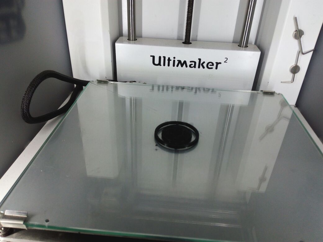
In our lab we use Ultimaker2 for 3D printings .The Ultimaker 2 3D printer has a great compact design, uses standard consumables,
and works very quietly. It has a large print platform, and the print plate is removable. The printer performs inconsistently when printing large
objects,can't print directly from a computer, and requires manual calibration. It's also very expensive.
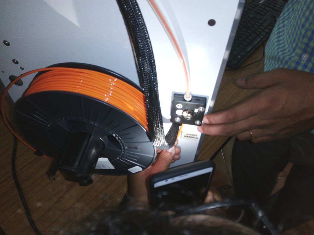
The Ultimaker 2 uses standard 2.85mm filaments with the motorized filament intake placed on its back, rather than the print-head.
Filaments are the raw material for 3D printing, just like ink cartridges in inkjet printers. They come in different colors and are basically
easy-to-melt, quick-congealing plastic strings that are fed through the print-head's nozzle during a print job. The print-head then heats up and
extrudes (that's why it's called an extruder) melted plastic on the print platform below to form the 3D object. This process is called fused
filament fabrication (FFF) and it's the current 3D-printing technology used in all consumer-grade 3D printers.
The Ultimaker 2 can handle both PLA and ABS filaments, but as a single extruder machine, it can use only one spool of filament at a time and therefore
can only print objects in one color. That's not a big deal, however, as you can always paint the object later.

The working of the ultimaker is provided briefly in the above figure . MAKE magazine classified the Ultimaker 2 as the "best open-architecture 3D printer of 2014"
Printer Evaluation-Group assignment
We have downloaded a test print model from thingiverse and is shown below with the test parameters.

size: the object is 2x50x30mm (baseplate)
hole size: 3 holes (3/4/5mm)
Nut size: M4 Nut should fit perfectly
fine details: pyramide, cone, all numbers
rounded print: wave, half sphere
minimum distance and walls: 0.1/0.2/0.3/0.4/0.5/0.6/0.7mm
overhang: 25°/30°/35°/40°/45°
bridge print: 2/4/8/16/mm
surface: all the flat parts

Test Results are provided below
| Sl.No | Paremeters | Visual Inspection | Physical Inspection |
|---|---|---|---|
| 1 | size: the object is 2x50x30mm (baseplate) | Size is OK,small warphage at corners | 1.6X48.83X28.9mm |
| 2 | hole size: 3 holes (3/4/5mm) | Visually OK | 2.7/3.84/4.74mm |
| 3 | Nut size: M4 Nut should fit perfectly | Visually OK | Can't fit the nut(deviation=1.2mm) Hole dia 6.6mm,Nut dia 7.8mm |
| 4 | fine details: pyramide, cone, all numbers | Visually OK | Minor deviations |
| 5 | rounded print: wave, half sphere | Visually OK | Printed correctly |
| 6 | minimum distance and walls: 0.1/0.2/0.3/0.4/0.5/0.6/0.7mm | Visually OK with minor defects | Exact measurements not taken but visually all printed |
| 7 | overhang: 25°/30°/35°/40°/45° | small breaks in walls | Visually verified,OK |
| 8 | bridge print: 2/4/8/16/mm | Visually OK | 2/4/8mm came correctly,16mm easily brokened |
| 9 | surface: all the flat parts | Visually OK | Small warphage at corners |
3D Printing
Rhinoceros 3D modeling
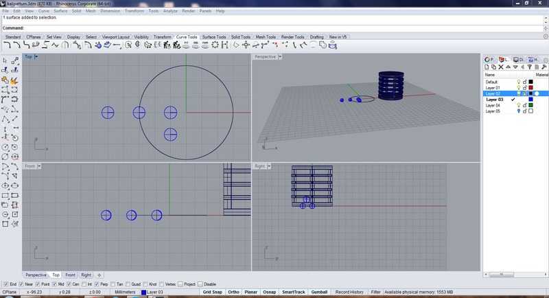
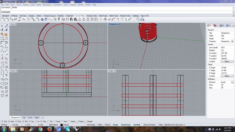
Using Rhyno I started my 3d designing of a locket and toy.In Rhyno software it is possible to do the designing using commands typed through keyboard in addition
to the toolbar and menu interface.I felt easy while working with commands. Some of the commands used by me include circle,rectangle,dim,distance,etc
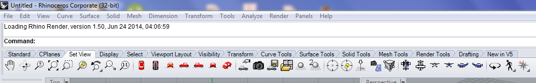
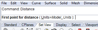
The above figure describes the region where the commands have to be provided while using rhino.We have to type the commands in the space provided after the Command.For example if
it is required to draw a circle ,just we have to type circle and press enter.
|
|
|---|
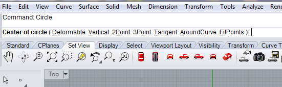
we have to select one of the item displayed in Center of circle region,I selected 2pointwhich means we have to click a point inside the drawing area and drag and place another point.Just after the Center of circle region is selected and first point is placed the new text Radius .. will be displayed .Select whether we need diameter ,radius etc and type the distance.

After doing these process we will finally get a circle of radius 3.We can precheck whether the radius is 3 or not by typing another command distance
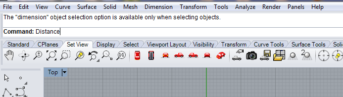
after distance is typed we have to move the curser point to the point from where we need the distance to be measured and click at that point ,then move to the point till where we need the distance measurement.
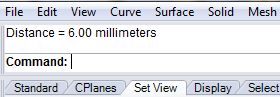
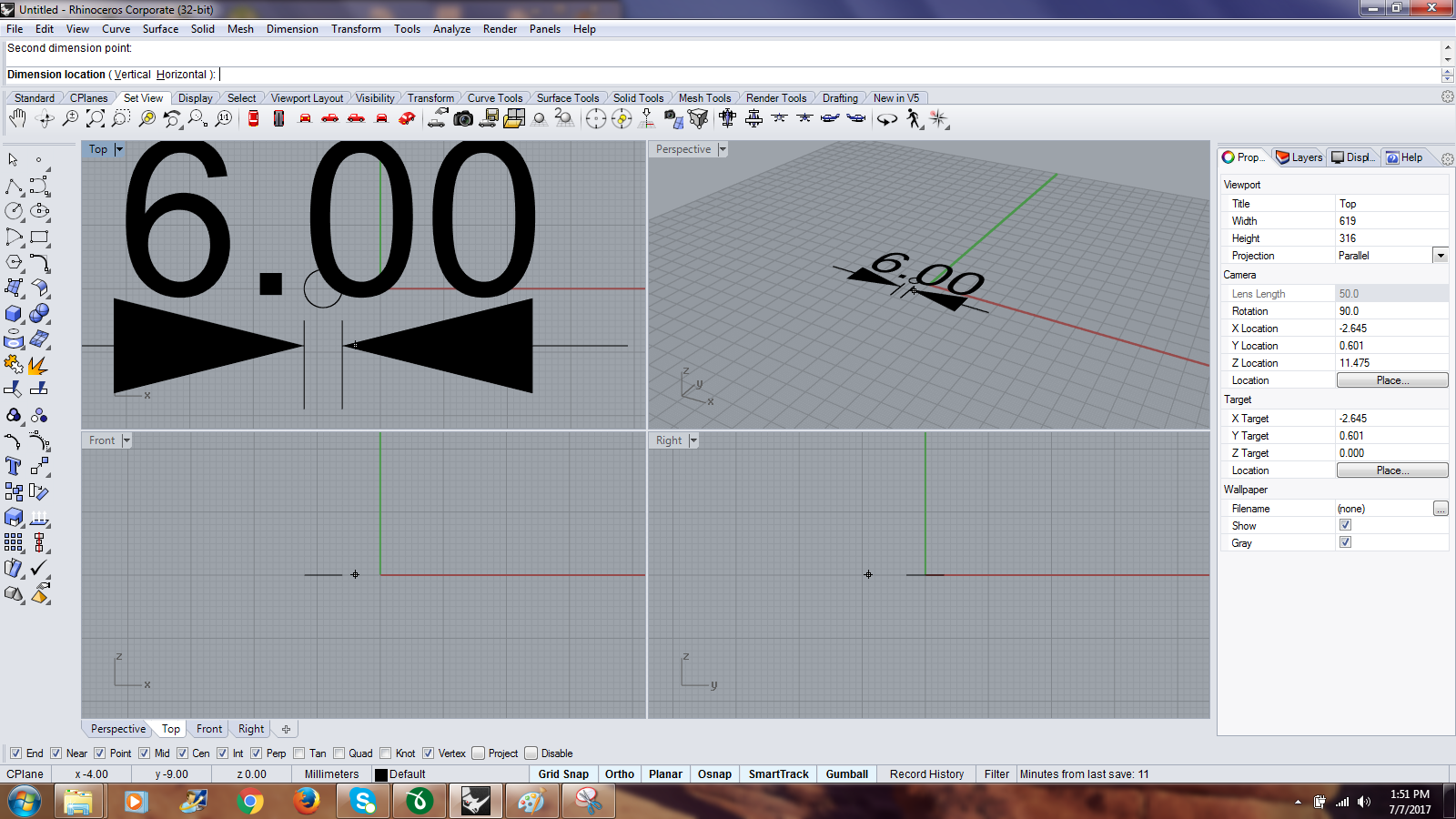
The Rhyno software provides four windows namely front,top,bottom and persceptive for visualizing our design .From the figure it is clear that the diameter of the circle is 6.

Finally the diameter of the circle is displayed after the text distance.
We can provide the dimensions of our design ,ie for example in my case the diameter of the circle in the window itself.The command dim should be used afterwards select the points between which dimensions has to be displayed in the window.
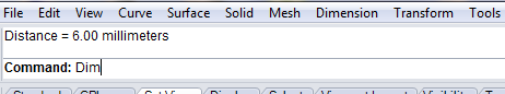
The figure below show how the dimensions have been entered inside the window .
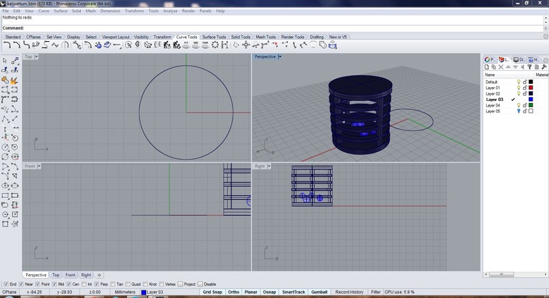
similarly using such command available finally I could model my design in rhyno.

|

|
|---|---|
|
|
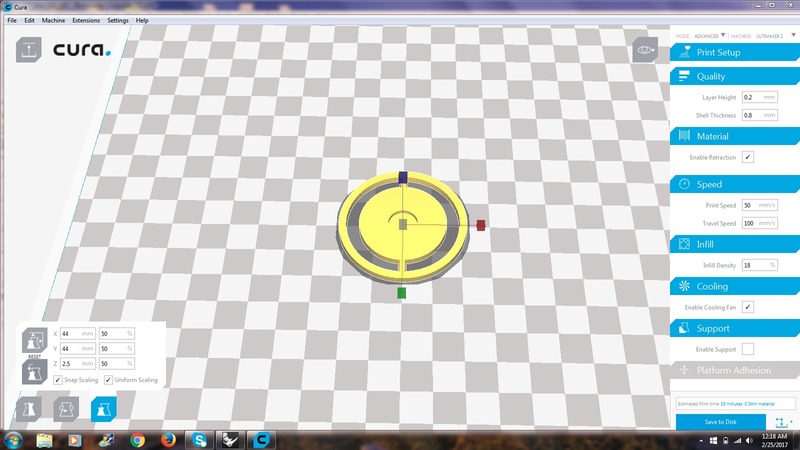
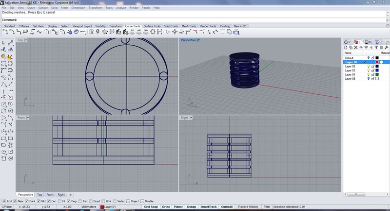
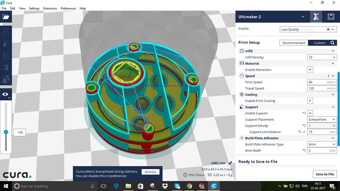
The designing involved in the making of locket is provided above.After designing the ,the file exported in stl format and then opened in cura software for converting to G-code.
G-code is a language in which tell computerized machine tools how to make something. The "how" is defined by instructions on where to move, how fast to move, and what path to follow. The most common situation is that, within a machine tool, a cutting tool is moved according to these instructions through a toolpath and cuts away material to leave only the finished workpiece. The same concept also extends to noncutting tools such as forming or burnishing tools, photoplotting, additive methods such as 3D printing, and measuring instruments.

|
|
|---|---|
|
|
|

|

|
|
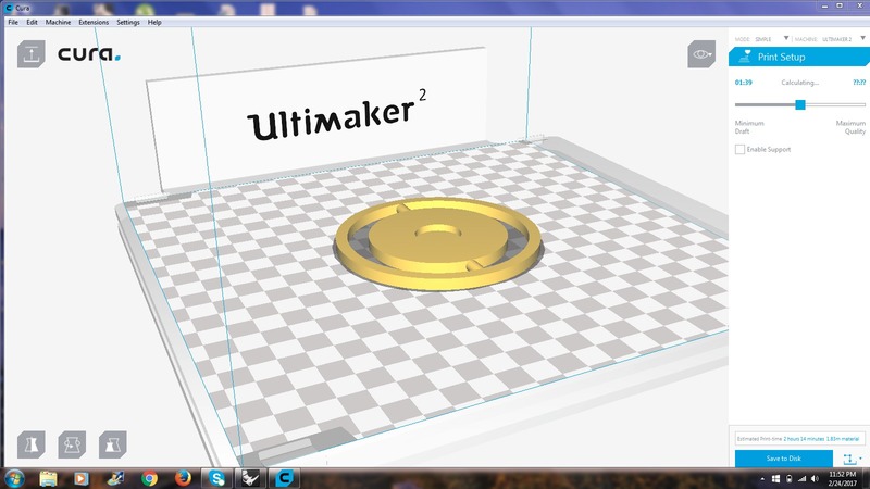
The designing involved in the making of toy is provided above. After doing this my confidence level in working with rhino got boosted

|

|
|---|
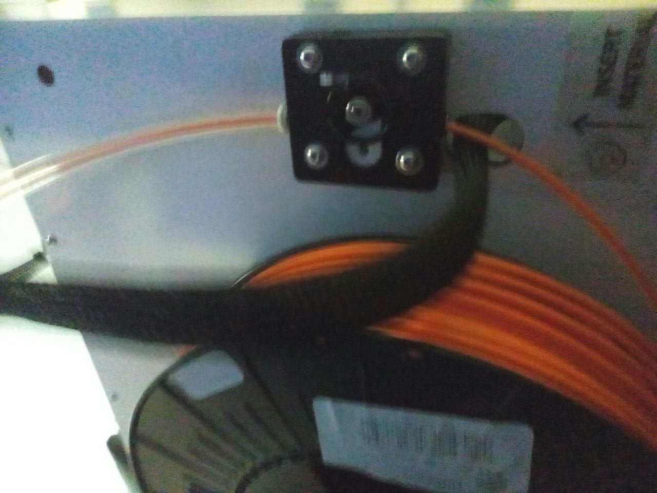
The extruder and the allen key in the ultimaker
|
|
|---|
There was a problem in the ultimaker while one of the student was printing,finally solved by build plate calibration .The PLA was breaked partially in the motor so that was also removed for making the ultimaker in working condition

|
|

|
|---|
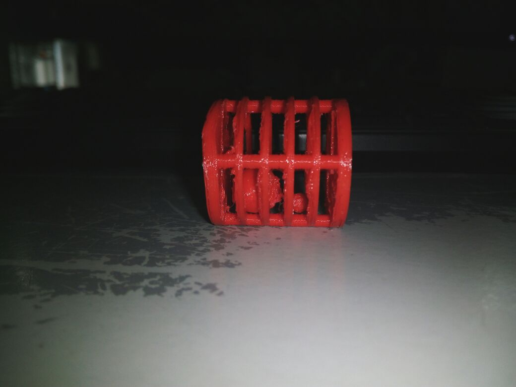
The Extruder is in the process of making the locket and the toy.It took 20 minutes for printing the locket and 2hrs for printing the toy
|
|
|---|---|
|
|
The toy has spheres of different radius inside it,which can't be done subtractivley.I exported it as .stl file and I used cura for making the gcode.
Download design file for toy
Download design file for locket
3D scanning
3D scanning is a process for capturing the shape of an object using a 3D scanner and saved in the computer as a 3D file.
There are Many different technologies available for 3D scanning an objects, environments and people. Each of these technologies comes some sort of limitations, advantages and costs.
The main aim is to collect the 3D data of the subject of intrest which can be an object, an environment or even people.
There are Some 3D scanner which are able to simultaneously scan shape and color data ,save the particular file in the system after that it can be even edited and atlast 3D printed.
3D scanners are having a great utlization in some of the dominant fields, such as automotive, aeronautics, dental, jewelry, video games, special effects and animation movies.
Different 3D scanning methods used in industries are given below.
Photogrammetry


Structured light


Contact based

Laser pulse

Laser triangulation
We have Kinect Xbox360, Intel Real sense F200 camera and Modela Machine available for Scanning. I started 3D scanning process with the installation of the Intel real sense drivers and SDK. The procedure used for the installation process is available here
Kinect Xbox360
Kinect can be used for 3D scanning in Windows,in order to 3d scan we have to install the drivers from here.
some scanning softwares which I came across are
Skanect,Kscan3D,SCENE Capture and ReconstructMe
Skanect
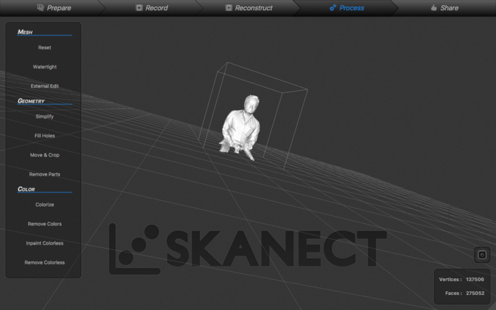
Skanect is actually an application software for 3D scanning which can capture full 3D colour of an object and process it. We can download the non commercial version software for free from here. After installing we have to place the scanner in such a position that its movement is restricted,and use a rotating chair for scanning ourself . So now an extra persons is required for rotating me and controlling the scanning process.First we have to Open the Skanect, Make a new project with appropriate setings with the "prepare" menu .

|

|
|---|---|

|
|
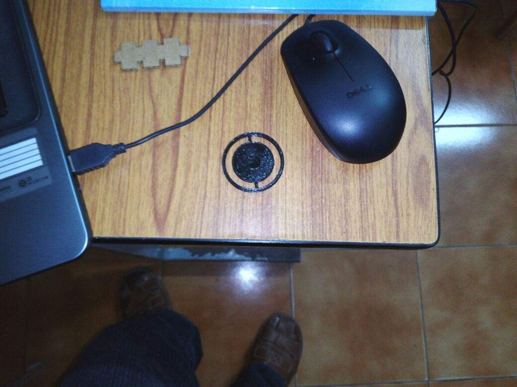
Next move to record menu ,you can see the bounding box appears and we need to check that the object is inside the bounding box. Once fixed we can start the scanning by pressing the record button on the extreme right corner with round inside a squre. Then we need to Move slowly around the object until you have managed to capture all the data we want. Then stop the scanning by pressing the record button again. If the scan becomes misaligned, just need to line up the black and white image overlay with the physical data until it snaps back. Sometimes, we may have to take multiple scans to get everything
The scanned file was exported in .stl format and uploded it into the sketchfab and the embedded stl file is shown below
design file for my 3d-image