Week 3: Computer-controlled Cutting
Assignment:
- Group assignment: make laser cutter test part(s), varying cutting settings and slot dimensions
- Individual assignment: cut something on the vinyl cutter
- Individual assignment: design, make, and document a parametric press-fit construction kit, accounting for the laser cutter kerf, which can be assembled in multiple ways
This week our task is to make lasercutter test part(s), varying slot dimensions using parametric functions, testing laser kerf and cutting settings (group project), cut something on the vinylcutter and finally design, make, and document a parametric press-fit construction kit, accounting for the lasercutter kerf, which can be assembled in multiple ways. Softwares which i used include Inkscape for vinyl cutting and Onshape for designing the press-fit.Material which i used for pressfit is Cardboard of 4mm size and Roland Vinyle for vinylcutting.
Vinyl Cutter

The vinyl cutter is capable of cutting thin flexible
sheets like vinyl through the vector path provided by
Fab module which is the software part used by the machine which
takes usually image file in png format,which is further converted
to corresponding vector path. The vecter image is finally loaded
in to the machine.
The basic steps followed in operating the machine includes
(1) In order to open the Fab module we have to type "fab " in the command terminal

the above window appears after the command,we have to select png for input format,Roland vinyl cutter for output process and finally click " on make_png_camm".
(2) Another window appears in which we have to load the image, for that i converted my logo to png format using inkscape . The logo converted to png format is given below.The design file is available in week2.

(3) Resize the image

(4) select vinyl as material and click "Make the path".The image will be converted to vector form.

Since my design is not so complex ,error (pixels) is made 1.4 . We should be careful while setting the value of force, it should be also changed in machine settings also.

5)After pushing down the lever in the backside ,place the vinyl sheet between two roller in such a way that the rollers should be alligned to the silver coloured bar on the roller bar ,then pull up the lever. Select the option whether we have placed peice or roll. Once the machine is set , Select "Make .camm" and select "Send it" in order to start cutting.

Finally i pasted my logo on my mobile phone , it looks good

Laser Cutting
Laser cutting is a precise method of cutting a design from a given material using a CAD file to guide it. There are three main types of lasers used in the industry CO2 lasers ,Nd and Nd-YAG. We use CO2 machines. This involves firing a laser which cuts by melting, burning or vaporizing your material .Trotec Speedy 100 a CO2 based Laser Cutting machine is used in our lab.
GROUP ASSIGNMENT
KERF

Kerf is defined as the width of material that is removed by a cutting process. It was originally used to describe how much wood was removed by a saw, because the teeth on a saw are bent to the side, so that they remove more material than the width of the saw blade itself, preventing the blade from getting stuck in the wood.When talking about CNC shape cutting with typical cutting processes, kerf is the width of material that the process removes as it cuts through the plate. The laser burns away a portion of material when it cuts through. This is known as the laser kerf and ranges from 0.08mm – 1mm depending on the material type and other conditional factors. During cutting the laser burns away the material along the vector path,Hence there is difference from the Intended dimensions . Long straight edges have a narrower kerf than slow curved edges. The kerf is also dependent on the cutting speed, which is affected by the radius of curvature of the cutting path. Laser kerf ranges from 0.08mm to 1mm depending on the material type and other conditional factors.
Why kerf width is important
When cutting parts on a CNC plasma or laser machine, you want to produce accurate cut parts, with final dimensions as close as possible to the programmed shape. So if you program a 6” by 6” square, and the plasma arc removes 0.200” of material, as it cuts, then the resulting part is going to be 5.9” by 5.9”. So the actual tool path has to be compensated by 0.100” to the side of the programmed path, all the way around the part. Rather than re-program the part at a different dimension, the CNC will take care of this automatically just by telling it which direction to offset, and by how much. Most modern CNCs take the actual kerf amount and automatically offset the tool path by 1/2 of that amount, so that the finished part comes out very close to the programmed dimensions. That is why the kerf value is often referred to as “kerf offset”.
FINDING KERF
In order to find the value of kerf we did experiments using craft wood and acrylic sheet. we identified gaps in between the cuts, which denotes laser kerf . In the case of craft wood we got kerf equals 0.325mm

Next we have done the same procedure for an acrylic sheet of thickness 3mm and calculated the value of kerf which is found to be 0.244mm.
POWER VARIATION TEST
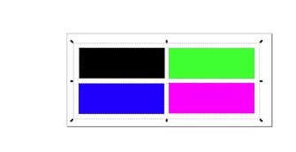
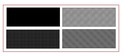
Here we engraved different rectangles by varying power. We mapped different colors with different powers and velocity for engraving. First we made a plate of different colored rectangles for engraving and we have set the power for each different values starting from black color power as 80,Power 60 to Blue color, Power 40 to Green and Power 20 to Violet. The plate is processed a nd we got different engraving depths in each as expected. Velocity was fixed as 10 and Frequency was not changed (auto).
|
|
|
|---|---|---|
| Design | Vector path | Output |
Parametric Design
As we all know that parametric design is a process of generation of geometry from the definition of a family of initial parameters and the design of the formal relations they keep with each other. It is about the use of variables and algorithms to generate a hierarchy of mathematical and geometric relations that allow you to generate a certain design, but to explore the whole range of possible solutions that the variability of the initial parameters may allow.
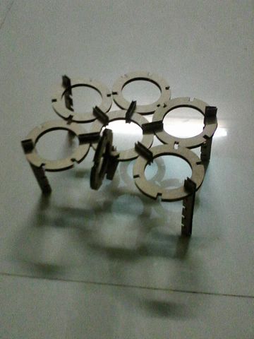
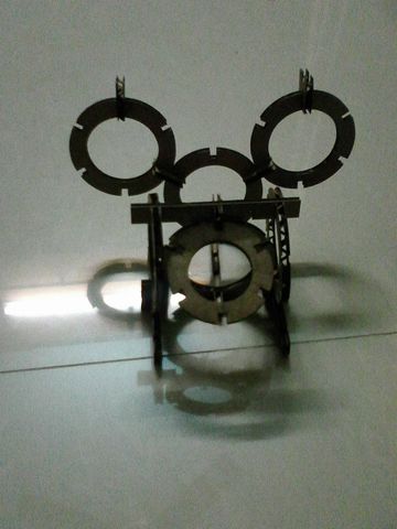
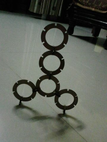
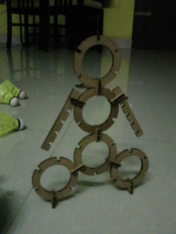
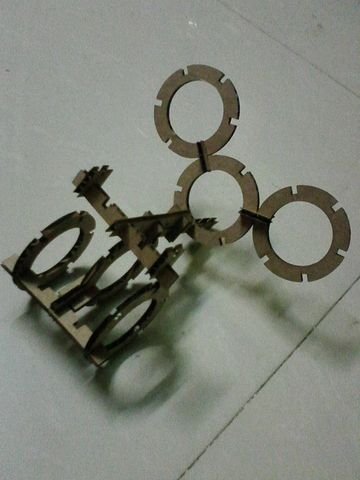
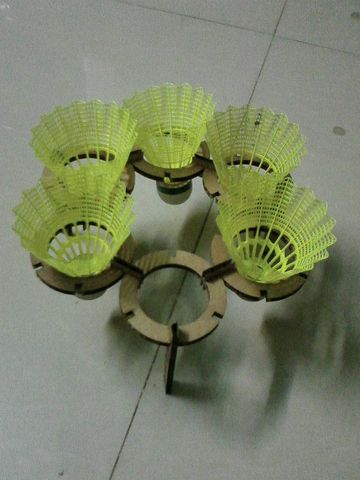
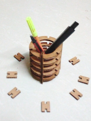
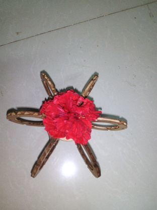
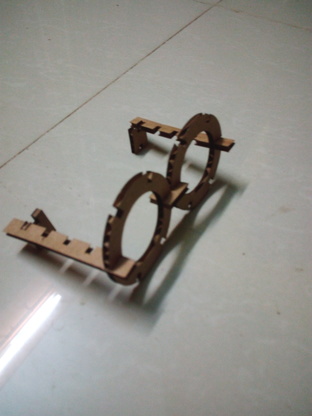
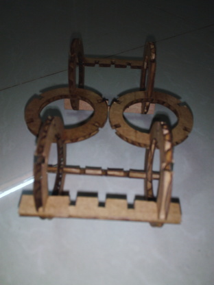
My design is parametric since ,it is visible from the photos that using just a circular and rectangular basic units it is possible to construct a bigger useful make. In parametric designing if any of the parameter is changed it result in change in other parameters too in the same fasion.


The above figure is a screenshot from onshape ,here in a line I defined the midpoint and the midpoint is maintained in the line even if the dimensions are changed.
I used cardboard for my pressfit work.I designed my pressfit model in onshape. I used a simple design .

While handling the laser machine first thing we have to do is to set the focus using the focusing tool.

Exhaust system of the lasercutter hould be turned ON before cutting process starts.

My onshape document is being exported as DXF file , which i imported in Rhino.

Select and Print from the design software , in the print settings set the power and velocity for both engraving and cutting.

Different materials will be having different power and velocity.

Finally we should confirm that red lines and black are used for cutting and engraving respectively.

Finally machine is ready to print

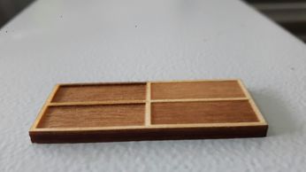
The parametric parts obtained after the laser cutting

The parametric parts obtained after the laser cutting joined differently to get different press fit models.
|
|

|
|---|---|---|
|
|

|
|
|
|
|
|
|
Download my design file from here