Week 10:Output Devices
Assignment:
- Add an output device to a microcontroller board you've designed and program it to do something
This week I decided to control servomotor using ATTINY44.In the previous week I have used arduino hardware to program the servomotor for load testing purpose. This week I thought of programming with embedded C.
SERVOMOTOR Controlled By Attiny44
This week I decided to use servomotor as output device to be controlled using Attiny44. I used servomotor because It is me given the task to program the FAB ARM, in which there are three SERVOMOTORS to be controlled. So it is better to work more with servomotor.
ATtiny44 BOARD
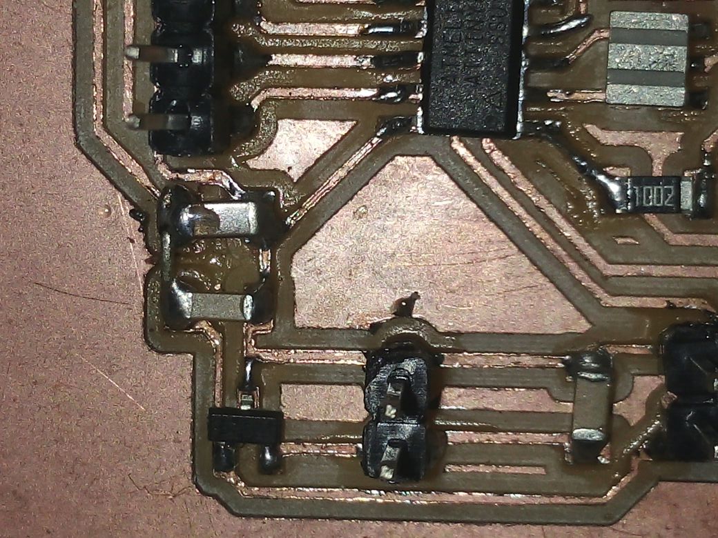
This week I have desinged ATtiny44 circuit board in eagle which is having the pinouts taken from PA0,PA1,PA2,PA3,PA6 and PA7 .Previously I have designed the circuit with ATtiny44 in Electronics Design week


design file are available here
Components used in the circuit
I used R2 a zero ohm resistor inorder to route .
-ATTINY44
-LM3480 voltage regulator
-ISP header
-resonator(20 MHz)
-capacitor 0.1uf,1 uf
-resistor 10k

I used autoroute,so I missed one common connection between the two capactors,so manually routed.
INTERFACING WITH SERVOMOTOR
I used Neils code for my first trial.The program rotates two servomotor,I only osed one pin PA6 and edited the code .
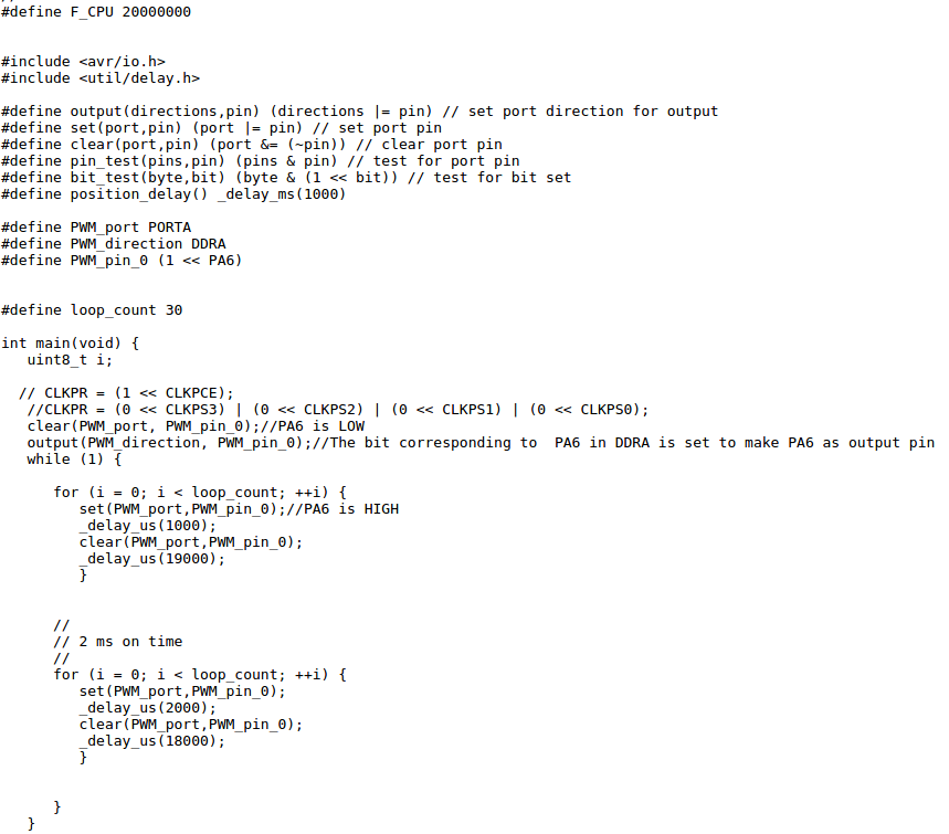
The code can be downloaded from here
Servos are often used to move robot arms and things alike, because they can rotate a specific amount of degrees very precisely, depending on the pulsewidth we feed it with the microcontroller. To move the servo, you need to send it a pulse. Depending on the duration of the pulse, the servo positions itself in a fixed position. This position is unique to the pulse duration. In other words, no matter what the current position of the servo is, it always rotates to the same position for a certain pulse duration.
Registers used for programming
AVR System Clock Prescaler: By default the clock on prescaled ATmega and ATtiny devices is divided by 8. The divide by 8 can be removed by un-programming the CKDIV8 fuse in the low fuse byte. It should be noted that the CKDIV8 fuse only affects the initial clock by setting. It sets the prescaler to divide by 8 at startup. It does not "lock" it there. You can change that at any time after reset by following the procedure to set the prescaler: Write the Clock Prescaler Change Enable (CLKPCE) bit to one and all other bits in CLKPR to zero. Within four cycles, write the desired value to CLKPS while writing a zero to CLKPCE.
PWM Signal Generation by Using AVR Timers.
The ATtiny44 system clock can be divided by setting the “CLKPR – Clock Prescale Register”
CLKPR – Clock Prescale Register

Bit 7 – CLKPCE: Clock Prescaler Change Enable The CLKPCE bit must be written to logic one to enable change of the CLKPS bits. The CLKPCE bit is only updated when the other bits in CLKPR are simultaniosly written to zero. CLKPCE is cleared by hardware four cycles after it is written or when the CLKPS bits are written. Rewriting the CLKPCE bit within this time-out period does neither extend the time-out period, nor clear the CLKPCE bit.
Bits 3:0 – CLKPS3:0: Clock Prescaler Select Bits 3 - 0
These bits define the division factor between the selected clock source and the internal system
clock. These bits can be written run-time to vary the clock frequency to suit the application
requirements. As the divider divides the master clock input to the MCU, the speed of all synchro-
nous peripherals is reduced when a division factor is used.

To avoid unintentional changes of clock frequency, a special write procedure must be followed
to change the CLKPS bits:
1. Write the Clock Prescaler Change Enable (CLKPCE) bit to one and all other bits in
CLKPR to zero.
2. Within four cycles, write the desired value to CLKPS while writing a zero to CLKPCE.
PULSE WIDTH MODULATION
Pulse Width Modulation (PWM) is a technique widely used in modern switching circuit to control the amount of power given to the electrical device. This method simply switches ON and OFF the power supplied to the electrical device rapidly. The average amount of energy received by the electrical device is corresponding to the ON and OFF period (duty cycle); therefore by varying the ON period i.e. longer or shorter, we could easily control the amount of energy received by the electrical device. The Light Emitting Diode (LED) will respond to this pulse by dimming or brighten its light while the electrical motor will respond to this pulse by turning its rotor slow or fast.


Most of the microcontroller PWM peripheral depends on the TIMER peripheral to provide the PWM signals frequency. The PWM peripheral will use the TIMER counter register (TCNT) as a digital step-up /down and continuously compare to the pre-determine duty cycle register (OCR – output compare register) value.When TCNT equal to OCR value the wave generator circuit will set (ON) or reset (OFF) the corresponding microcontroller PWM I/O ports.
Timer
The value of the timer register increases/decreases automatically. In AVR, timers are of two types: 8-bit and 16-bit timers. In an 8-bit timer, the register used is 8-bit wide whereas in 16-bit timer, the register width is of 16 bits. The 8-bit timer is capable of counting 2^8=256 steps from 0 to 255 as demonstrated below.

Similarly a 16 bit timer is capable of counting 2^16=65536 steps from 0 to 65535. Due to this feature, timers are also known as counters. The best part is that the timer is totally independent of the CPU. Thus, it runs parallel to the CPU and there is no CPU’s intervention, which makes the timer quite accurate.
Now suppose, we need to flash an LED every 10 ms. This implies that its frequency is 1/10ms = 100 Hz.
Now let’s assume that we have an external crystal XTAL of 4 MHz. Hence, the CPU clock frequency is 4 MHz.
Now, as I said that the timer counts from 0 to TOP. For an 8-bit timer, it counts from 0 to 255 whereas
for a 16-bit timer it counts from 0 to 65535. After that, they overflow. This value changes at every clock pulse.
Let’s say the timer’s value is zero now. To go from 0 to 1, it takes one clock pulse. To go from 1 to 2, it takes another clock pulse.
To go from 2 to 3, it takes one more clock pulse. And so on. For F_CPU = 4 MHz, time period T = 1/4M = 0.00025 ms. Thus for every transition
(0 to 1, 1 to 2, etc), it takes 0.00025 ms.Now, as stated above, we need a delay of 10 ms. This maybe a very short delay,
but for the microcontroller which has a resolution of 0.00025 ms, its quite a long delay. To get an idea of how long it takes,
let’s calculate
Substitute Required Delay = 10 ms and Clock Time Period = 0.00025 ms, and you get Timer Count = 39999.Now, to achieve this, we definitely cannot use an 8-bit timer (as it has an upper limit of 255, after which it overflows). Hence, we use a 16-bit timer (which is capable of counting up to 65535) to achieve this delay.
The Prescaler
Assuming F_CPU = 4 MHz and a 16-bit timer (MAX = 65535), and substituting in the above formula, we can get a maximum delay of 16.384 ms.
if we need a greater delay, for example 20 ms we have another option
Suppose if we decrease the F_CPU from 4 MHz to 0.5 MHz (i.e. 500 kHz), then the clock time period increases to 1/500k = 0.002 ms. Now if we substitute Required Delay = 20 ms and Clock Time Period = 0.002 ms, we get Timer Count = 9999 so this can easily be achieved using a 16-bit timer. At this frequency, a maximum delay of 131.072 ms can be achieved.
This technique of frequency division is called prescaling. We do not reduce the actual F_CPU. The actual F_CPU remains the same (at 4 MHz in this case). So basically, we derive a frequency from it to run the timer. Thus, while doing so, we divide the frequency and use it. There is a provision to do so in AVR by setting some bits in registers specified for that.
There is a trade-off between resolution and duration. As we have seen above, the overall duration of measurement has increased from a mere 16.384 ms to 131.072 ms. So has the resolution. The resolution has also increased from 0.00025 ms to 0.002 ms (technically the resolution has actually decreased). This means each tick will take 0.002 ms. The problem is that the accuracy has decreased. Earlier, you were able to measure duration like 0.1125 ms accurately (0.1125/0.00025 = 450), but now you cannot (0.1125/0.002 = 56.25). The new timer can measure 0.112 ms and then 0.114 ms. No other value in between.
Choosing Prescalers:Let’s take an example. We need a delay of 184 ms . We have F_CPU = 4 MHz.
The AVR offers us the following prescaler values to choose from: 8, 64, 256 and 1024. A prescaler of 8 means the effective clock
frequency will be F_CPU/8. Now substituting each of these values into the above formula, we get different values of timer value.

Now out of these four prescalers, 8 cannot be used as the timer value exceeds the limit of 65535. Also, since the timer always takes up integer values, we cannot choose 1024 as the timer count is a decimal digit. Hence, we see that prescaler values of 64 and 256 are feasible. But out of these two, we choose 64 as it provides us with greater resolution. We can choose 256 if we need the timer for a greater duration elsewhere. Thus, we always choose prescaler which gives the counter value within the feasible limit (255 or 65535) and the counter value should always be an integer.
Using intrupt mechanism ,when counter overflows, we can set up a bit to fire an interrupt . Now, during execution of the program, whenever an overflow occurs, an interrupt is fired and the CPU attends to the corresponding ISR. Now it’s up to us what do we want to do inside the ISR. We can toggle the value of a pin, or increment a counter, etc etc.
In AVR, there are three types of timers – TIMER0, TIMER1 and TIMER2. Of these, TIMER1 is a 16-bit timer whereas others are 8-bit timers.
In ATtiny44 we have One 8-Bit and One 16-Bit Timer/Counter with Two PWM Channels, Each.
Registers related Timer0
From the above discussions , with a clock frequency of 32 kHz and 8-bit counter, the maximum delay possible is of 8 ms. If our requirement is a delay of 6 ms, we need a timer count of 191. This can easily be achieved with an 8-bit counter (MAX = 255). We need to keep a track of the counter value. As soon as it reaches 191, we toggle the LED value and reset the counter. For this, we need the help of the following registers.
TCNT0 Register
This is where the uint 8-bit counter of the timer resides. The value of the counter is stored here and increases/decreases automatically. Data can be both read/written from this register

TCCR0 Register

By selecting the hilighted Clock Select Bits, we set the timer up by choosing proper prescaler. The possible combinations are given below.
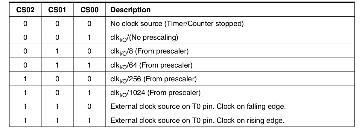
For not choosing Prescaling the command used in AVR C is TCCR0 |= (1 << CS00);
if we do not initialize this register, all the bits will remain as zero and the timer/counter will remain stopped.
TIMSK Register
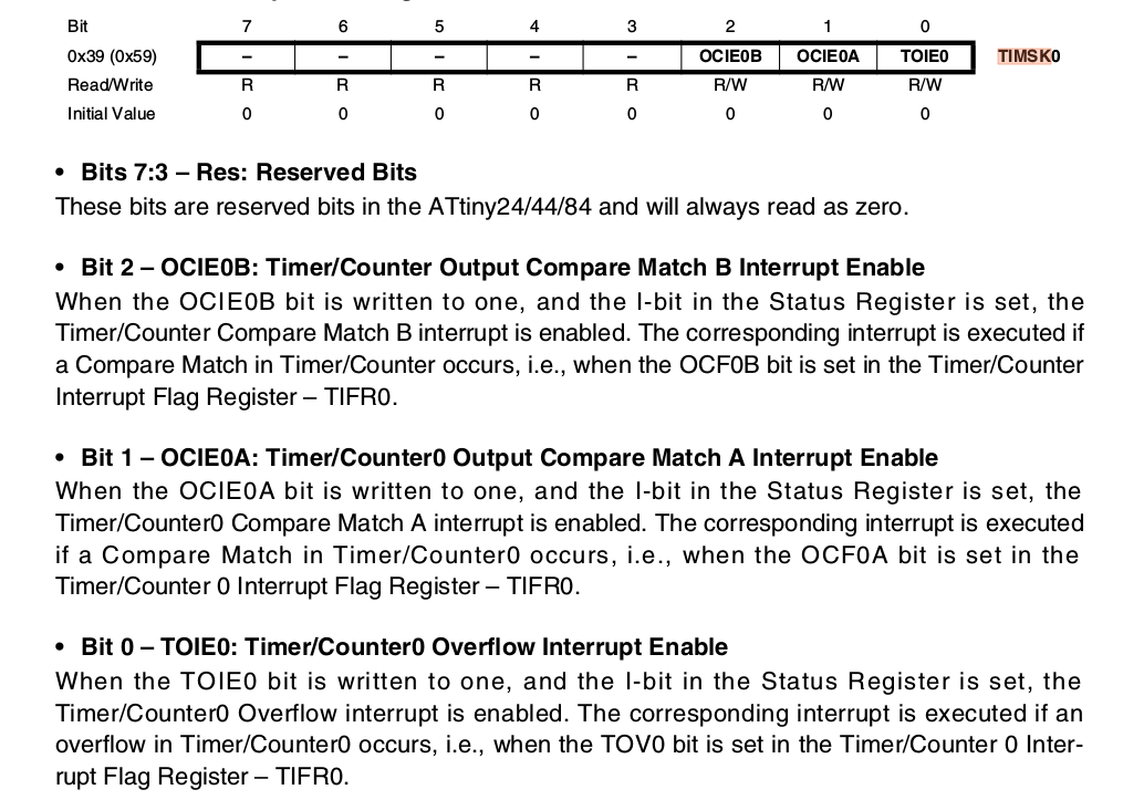
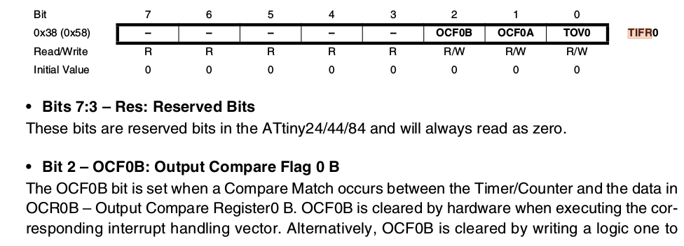
TIFR Register

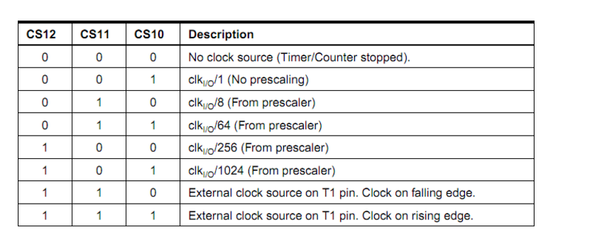
TCCR1B Register
The bit 2:0 – CS12:10 are the Clock Select Bits of TIMER1.

TCNT1 Register

It is 16 bits wide since the TIMER1 is a 16-bit register. TCNT1H represents the HIGH byte whereas TCNT1L represents the LOW byte. The timer/counter value is stored in these bytes.
TIMSK Register

Bit 5 – ICIE1: Timer/Counter1, Input Capture Interrupt Enable
When this bit is written to one, and the I-flag in the Status Register is set (interrupts globally
enabled), the Timer/Countern Input Capture interrupt is enabled. The
corresponding Interrupt Vector is executed when the
ICF1 Flag, located in TIFR1, is set.
• Bit 2 – OCIE1B: Timer/Counter1, Output Compare B Match Interrupt Enable
When this bit is written to one, and the I-flag in the Status Register is set (interrupts globally
enabled), the Timer/Counter1 Output Compare B Match interrupt is enabled. The corresponding
Interrupt Vector is executed when the OCF1B flag, located in
TIFR1, is set.
• Bit 1 – OCIE1A: Timer/Counter1, Output Compare A Match Interrupt Enable
When this bit is written to one, and the I-flag in the Status Register is set (interrupts globally
enabled), the Timer/Counter1 Output Compare A Match interrupt is enabled. The corresponding
Interrupt Vector is executed when the OCF1A flag, located in
TIFR1, is set.
• Bit 0 – TOIE1: Timer/Counter1, Overflow Interrupt Enable
When this bit is written to one, and the I-flag in the Status Register is set (interrupts globally
enabled), the Timer/Counter1 Overflow interrupt is enabled. The corresponding Interrupt Vector
is executed when the TOV1 flag, located in TIFR1, is set.
TIFR Register

• Bit 5 – ICF1: Timer/Counter1, Input Capture Flag
This flag is set when a capture event occurs on the ICP1 pin. When the Input Capture Register
(ICR1) is set by the WGM13:0 to be used as the TOP value, the ICF1 flag is set when the coun-
ter reaches the TOP value.
ICF1 is automatically cleared when the Input Capture Interrupt Vector is executed. Alternatively,
ICF1 can be cleared by writing a logic one to its bit location.
• Bit 2 – OCF1B: Timer/Counter1, Output Compare B Match Flag
This flag is set in the timer clock cycle after the counter (TCNT1) value matches the Output
Compare Register B (OCR1B).
Note that a Forced Output Compare (1B) strobe will not set the OCF1B flag.
OCF1B is automatically cleared when the Output Compare Match B Interrupt Vector is exe-
cuted. Alternatively, OCF1B can be cleared by writing a logic one to its bit location.
• Bit 1 – OCF1A: Timer/Counter1, Output Compare A Match Flag
This flag is set in the timer clock cycle after the counter (TCNT1) value matches the Output
Compare Register A (OCR1A).
Note that a Forced Output Compare (1A) strobe will not set the OCF1A flag.
OCF1A is automatically cleared when the Output Compare Match A Interrupt Vector is exe-
cuted. Alternatively, OCF1A can be cleared by writing a logic one to its bit location.
• Bit 0 – TOV1: Timer/Counter1, Overflow Flag
The setting of this flag is dependent of the WGM13:0 bits setting. In Normal and CTC modes,
the TOV1 flag is set when the timer overflows.
TOV1 is automatically cleared when the Timer/Counter1 Overflow Interrupt Vector is executed.
Alternatively, TOV1 can be cleared by writing a logic one to its bit location.