Building Menu
Building And Engraving The Base
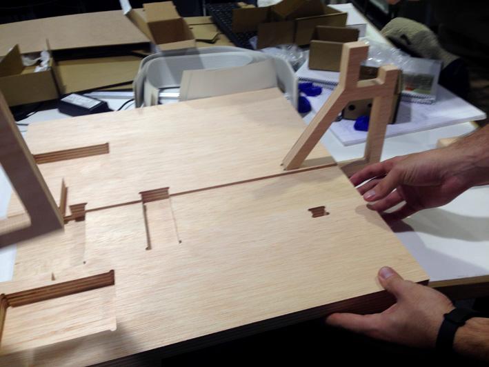
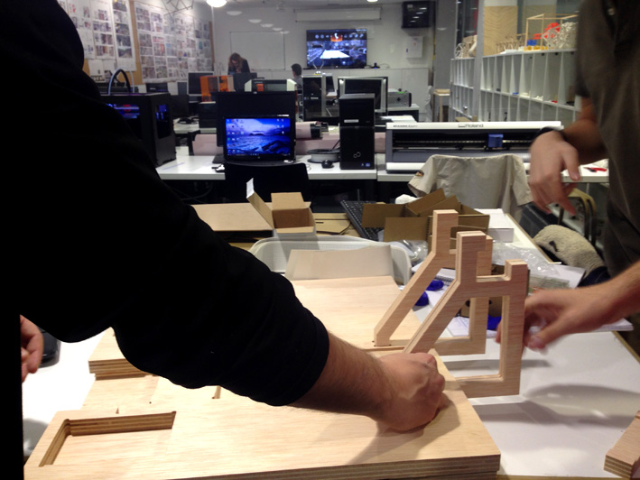
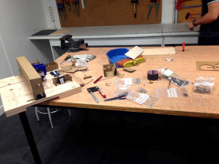
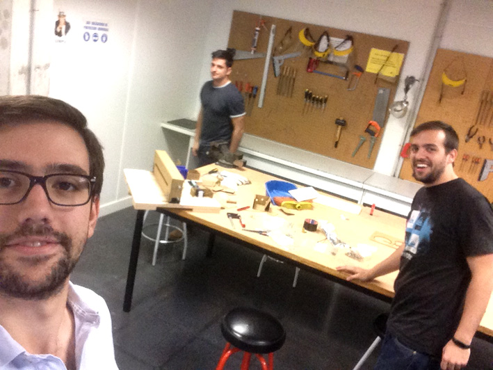
Building the Base
After cutting the 20mm Plywood with the CNC machine, we started to build up the base
and other components to make sure everything was in order before engraving.
Building The Base
Building The Base
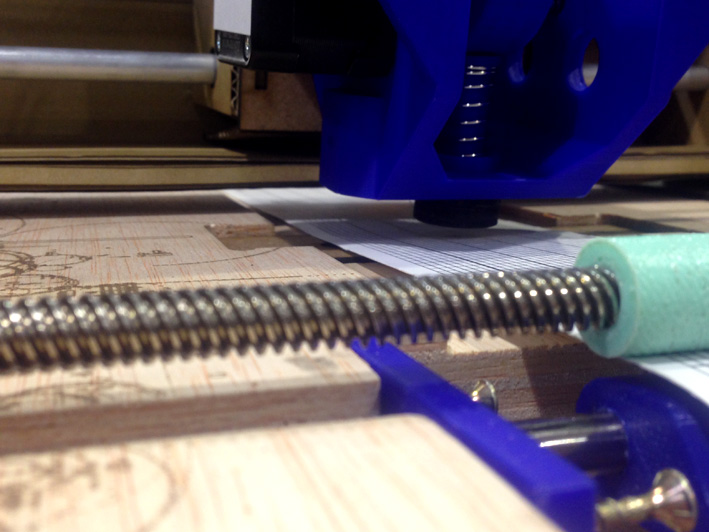
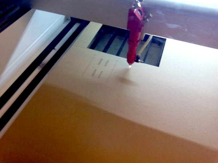
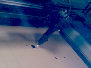
Engraving the base
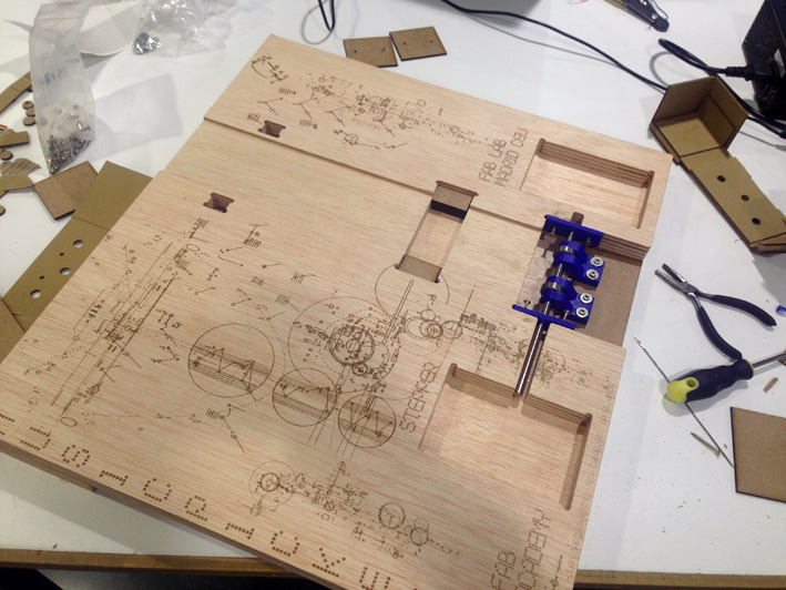
The Base Engraved
Here is a timelapse video:
Engraving the base
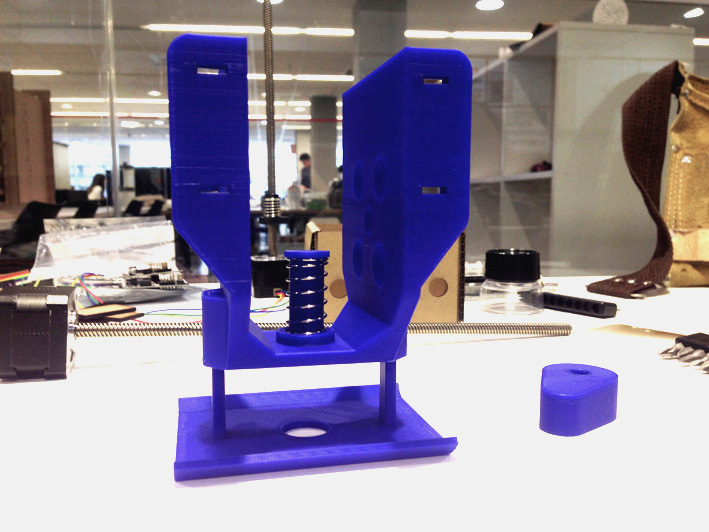
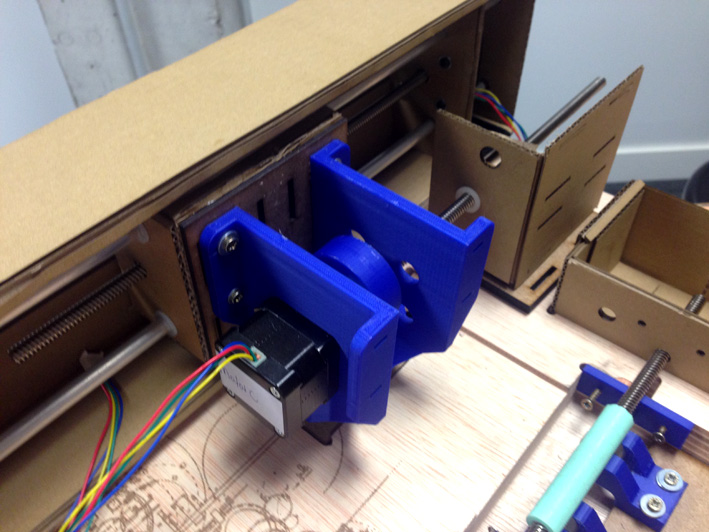
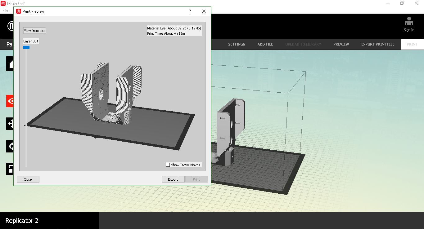
Building the Head
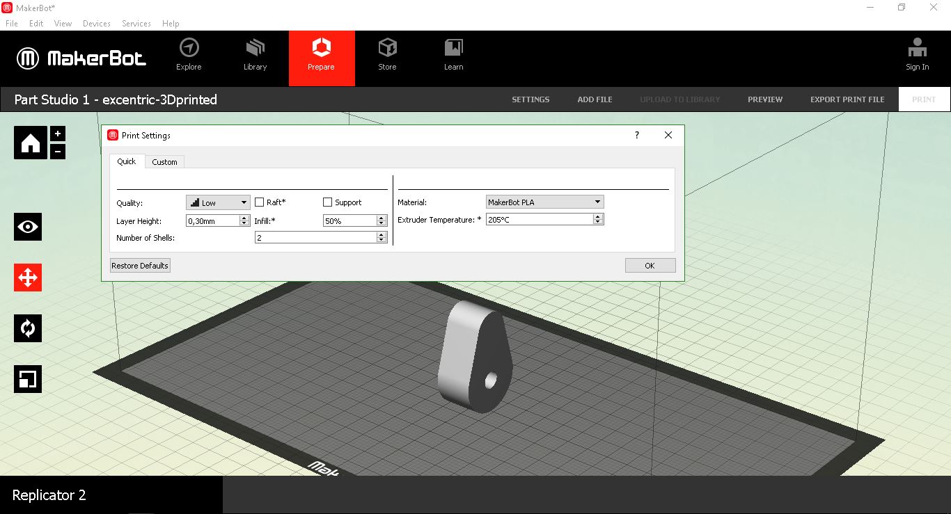
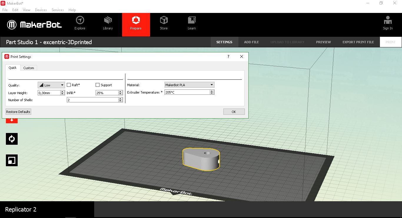
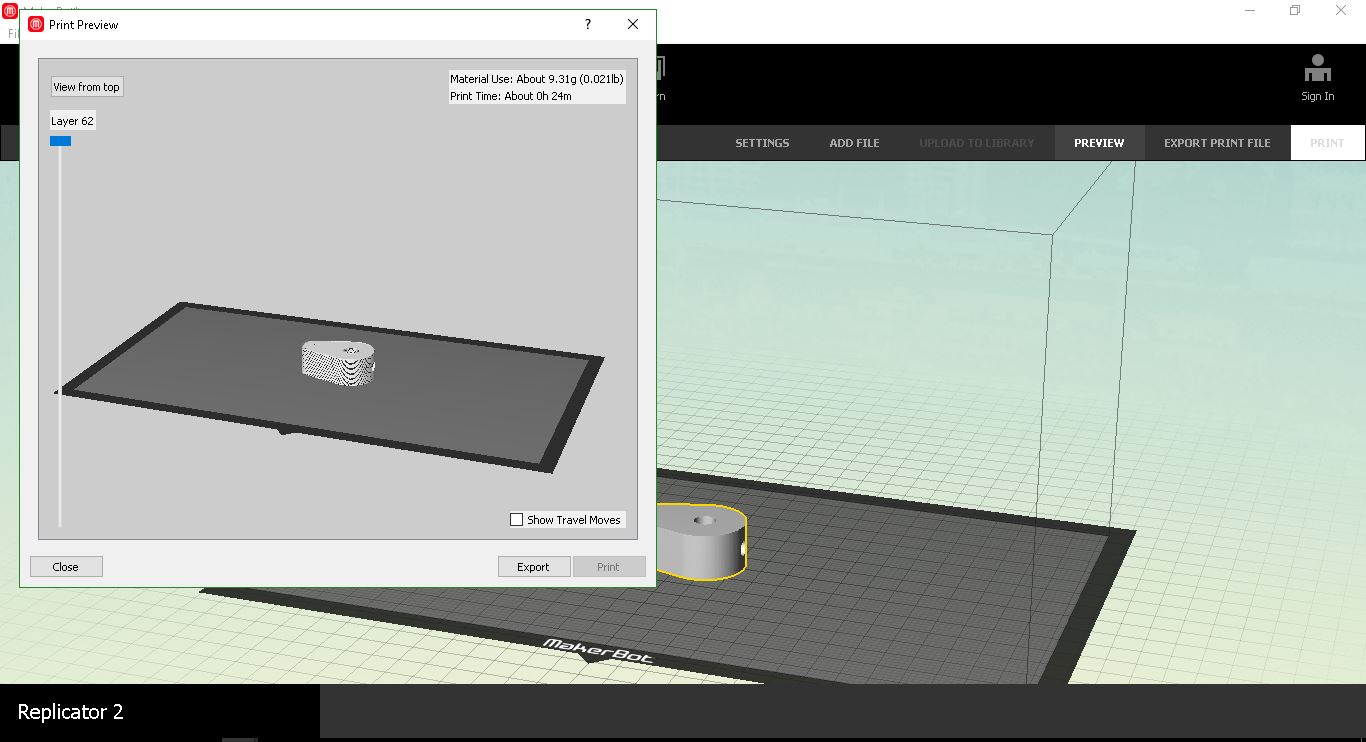
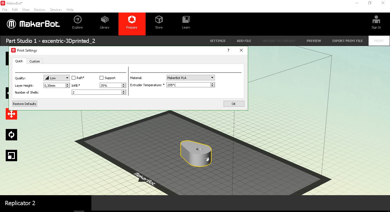
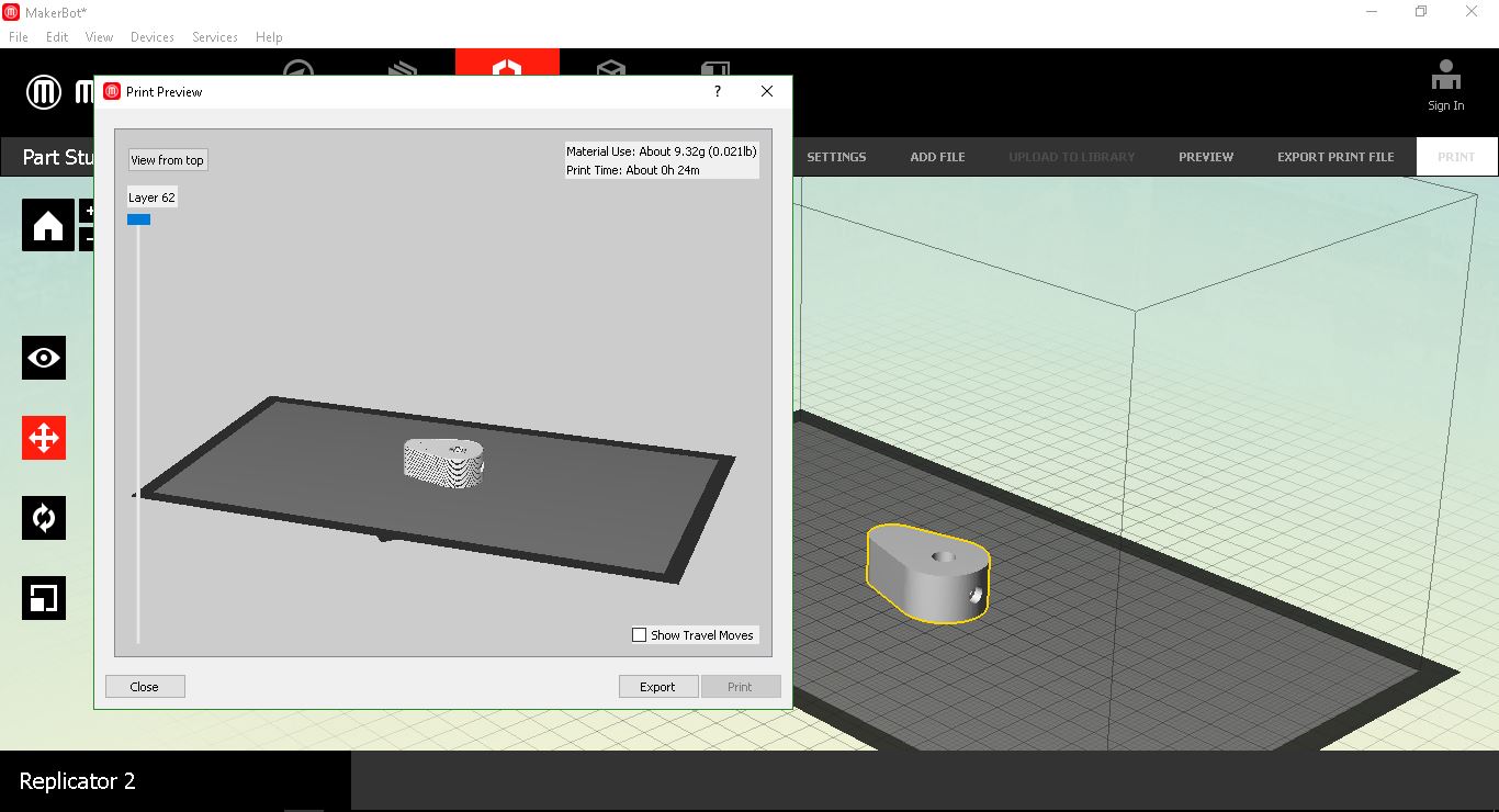
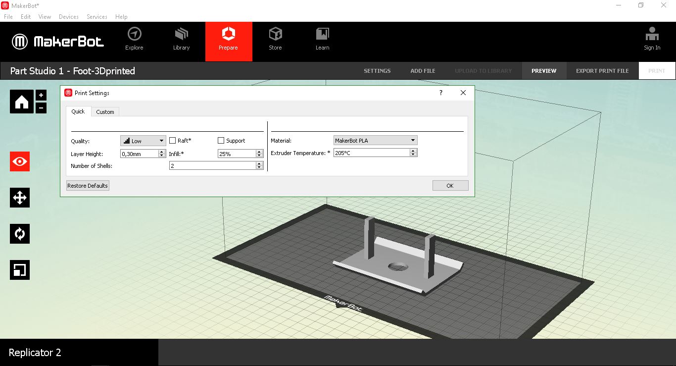
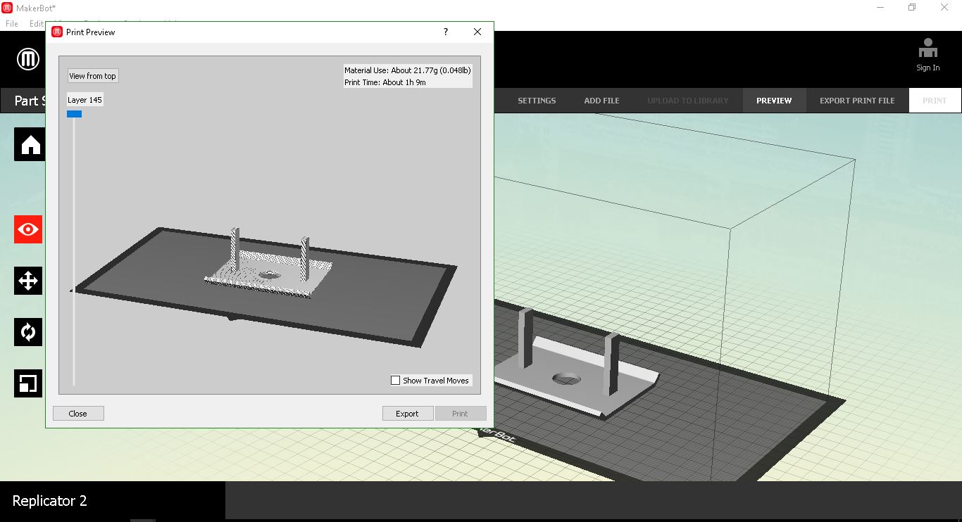
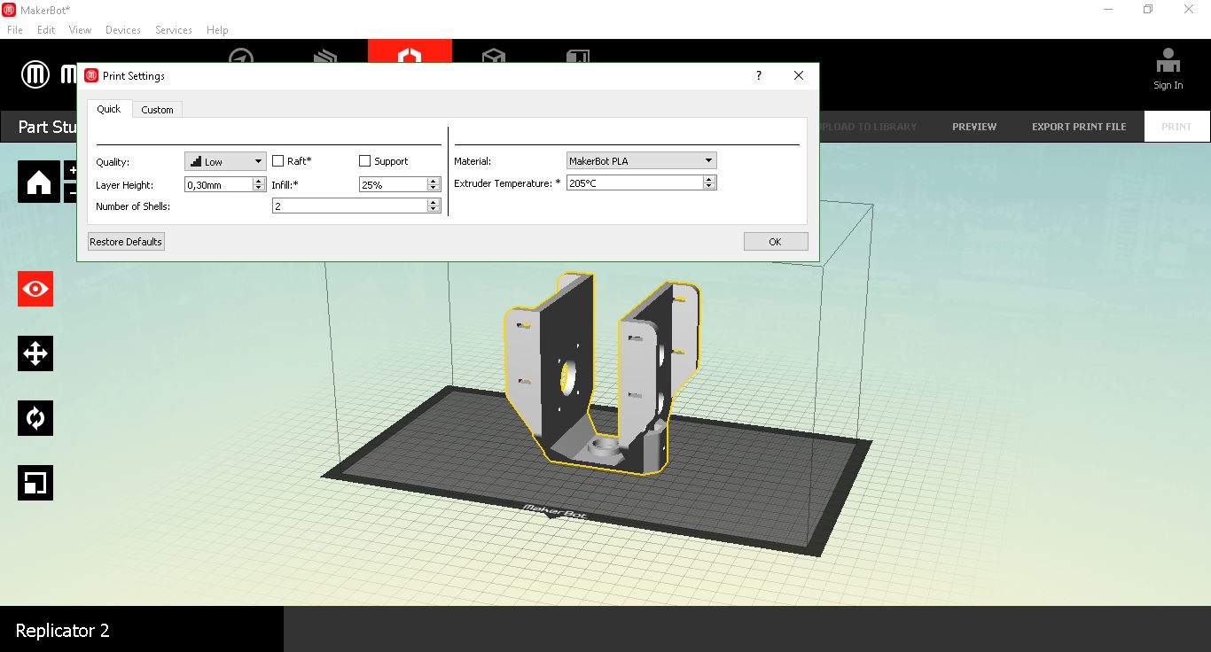
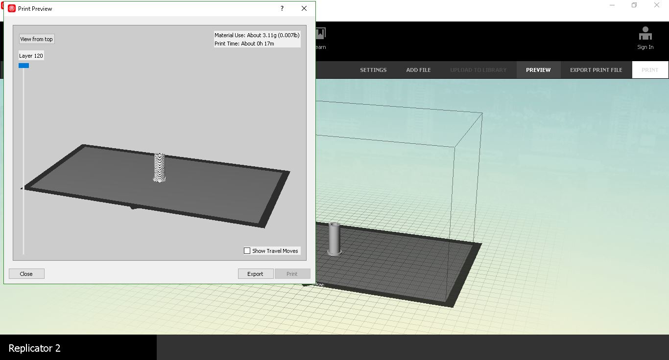
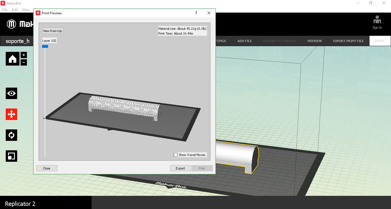
As every part of the head was done with PLA, it took a long time to print everything. Only the big piece took 4 hours and 30 minutes.
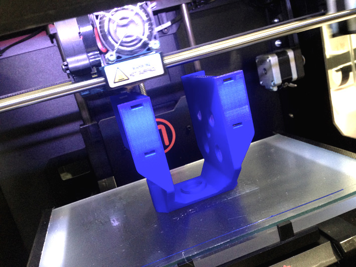
Printing The Holder
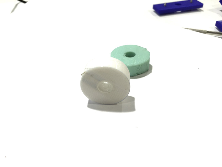
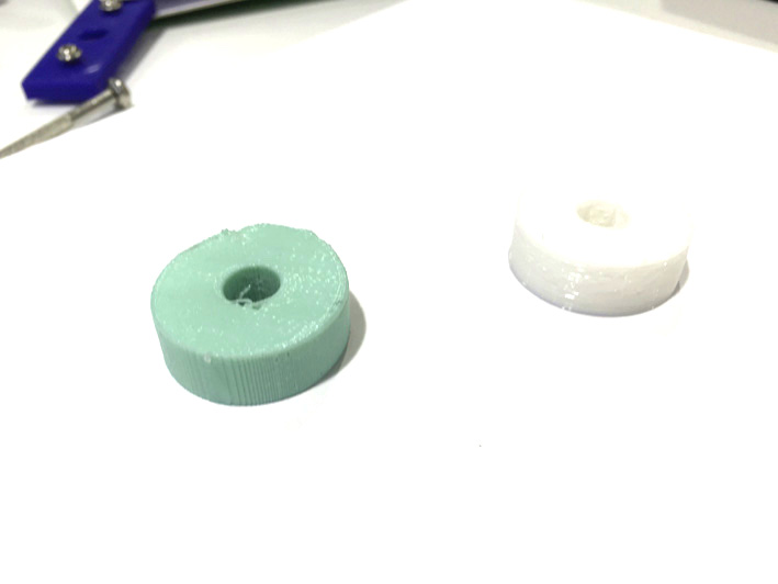
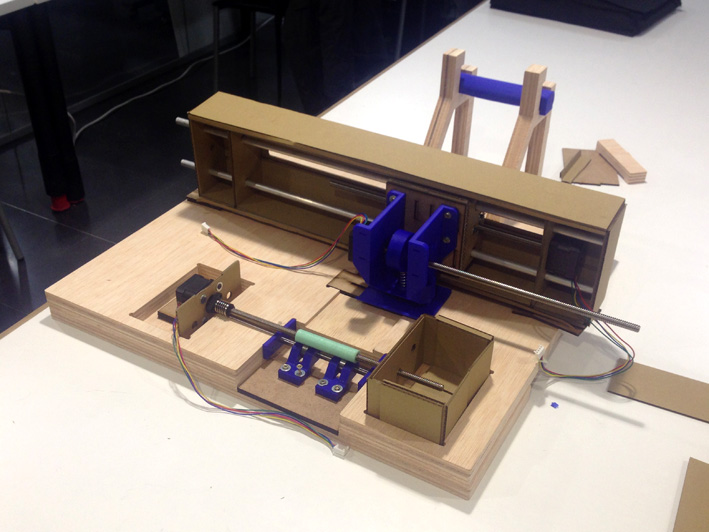
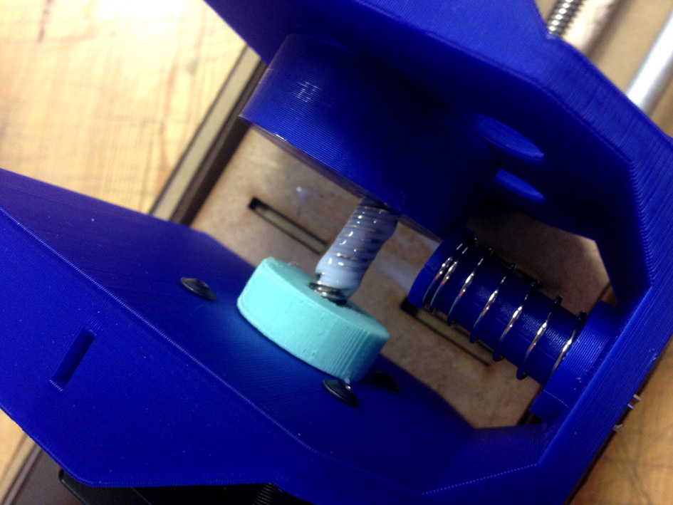
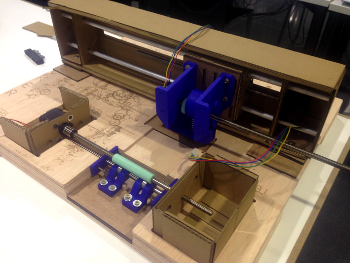
Once we had everything printer, we started to assemble it together to see if it worked correctly. As mentioned on the 'Tests' Website', we had to design a new rotary part to transform rotation to an upward and downward movement.
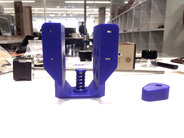
The Holder + Shaft
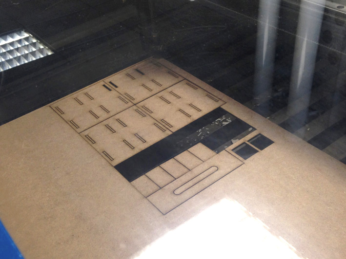
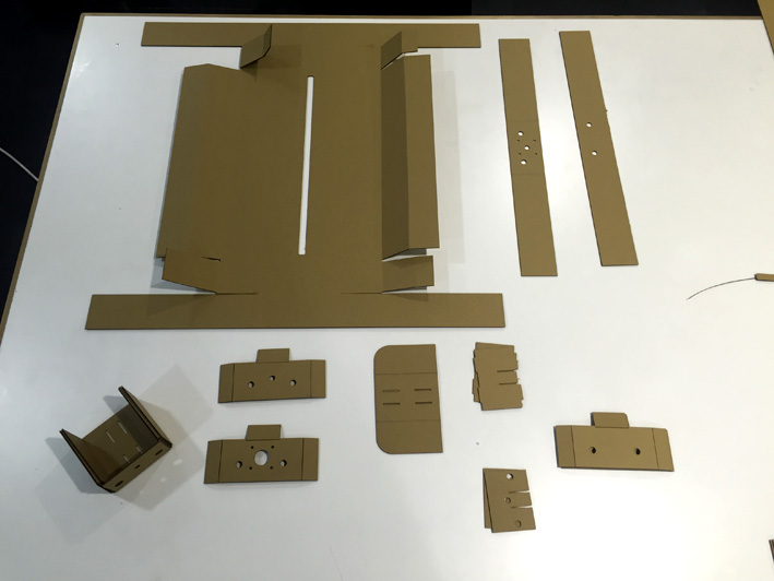
Lasercutting Other MD Wood Pieces For The Head
Holder + Shaft
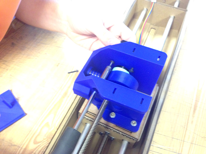
Moving The Head
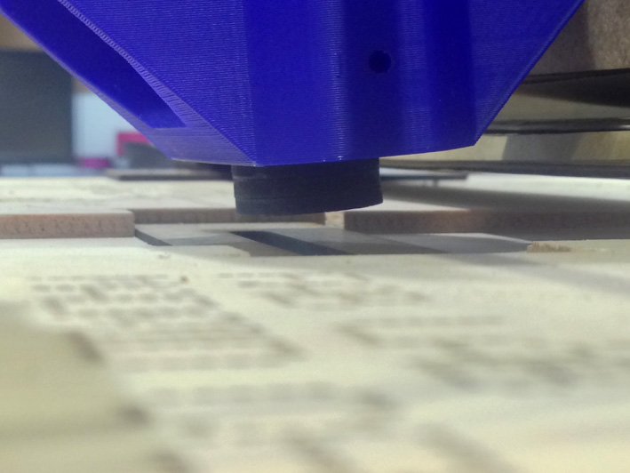
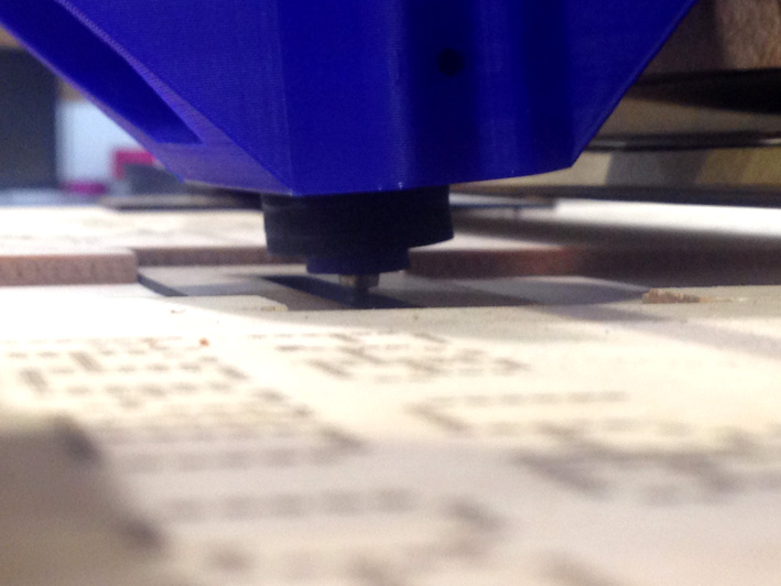
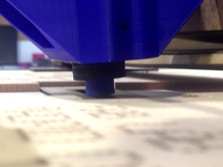
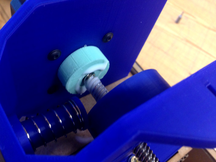
This upward and downward movement was not as vertical as we thought, therefore we added several 3mm Medium Density Wood Rings to the lower part of the shaft to guide it in the direction we wanted. We wanted to make sure where the punch hole was done.
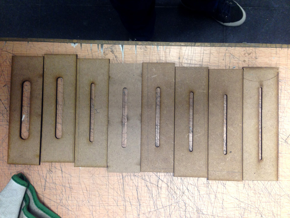
Different Widths
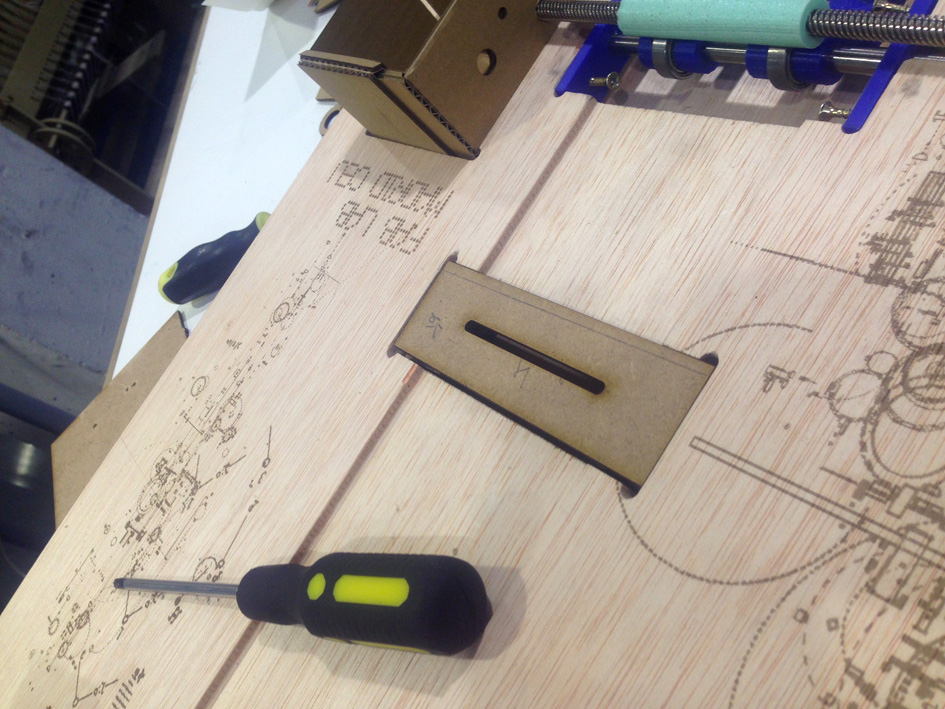
6.5mm width
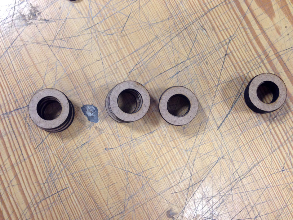
Shaft's Guidance
Testing the Head -Punching Mechanism
In order to make the hole, we need at the end of the shaft a hole where the punch can go through while holding the paper.
Punching Process

Punching Process
Punching Process
Punching Process
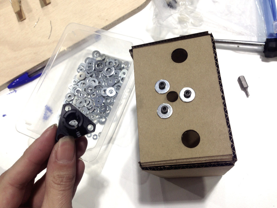
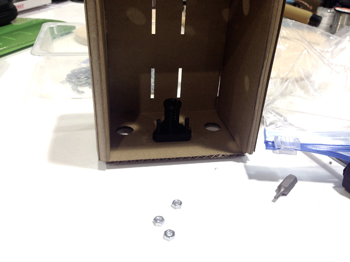
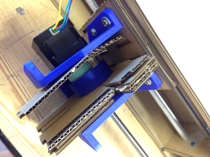
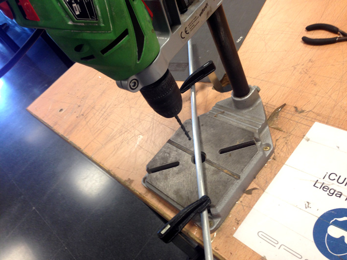
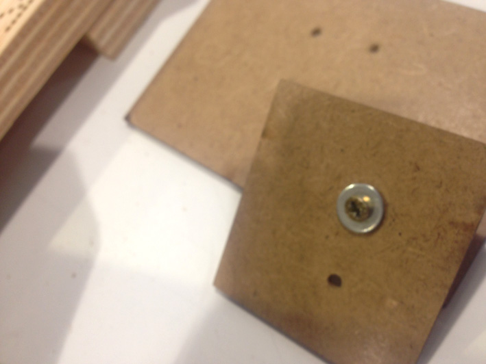
The rest of the head was easy to assemble using 3mm diameter screws to the cardboard box with a 3mm Medium Density Wood Plate.
The Head + Added Element To Hold It When Punching
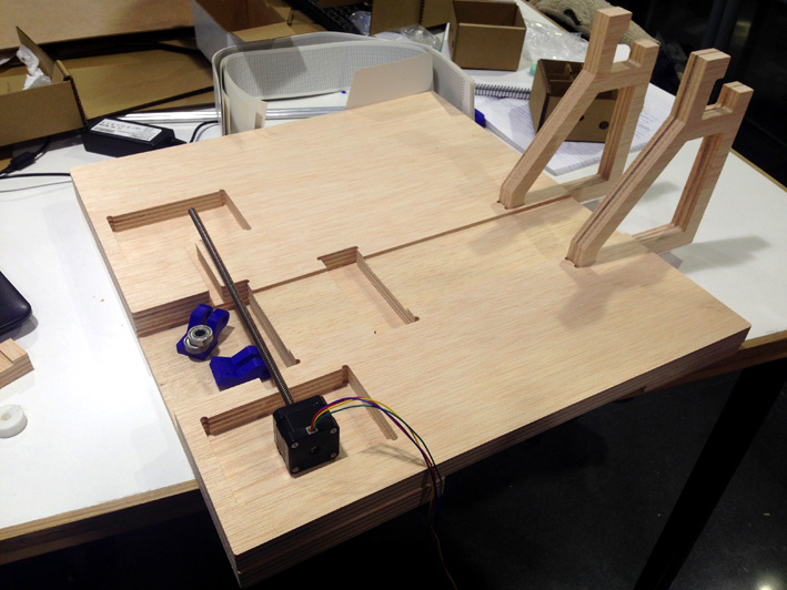
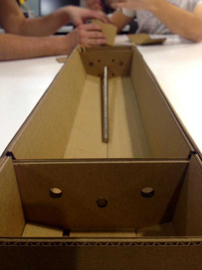
Building the Rolling System Mechanism Used for Pulling the Music Paper
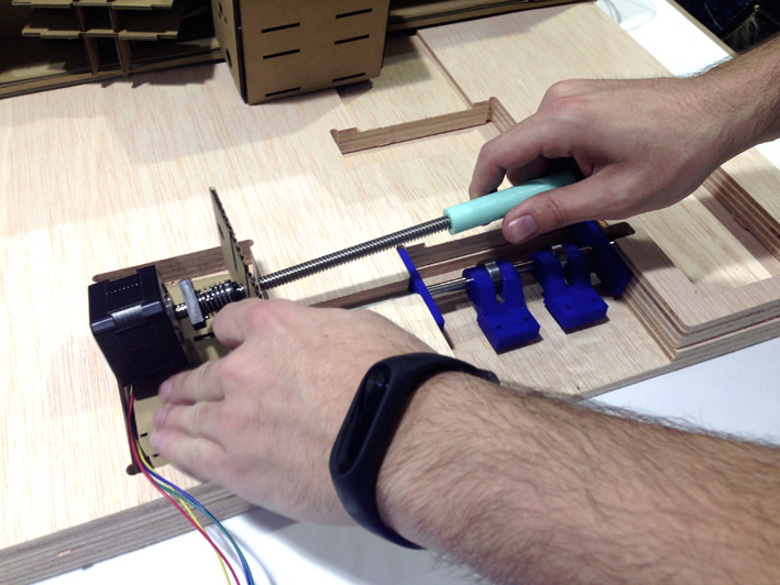
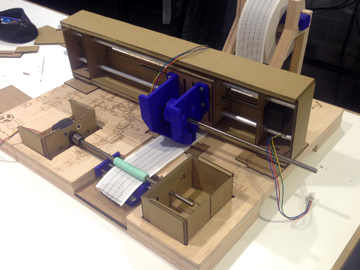
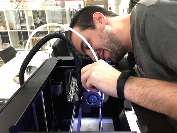
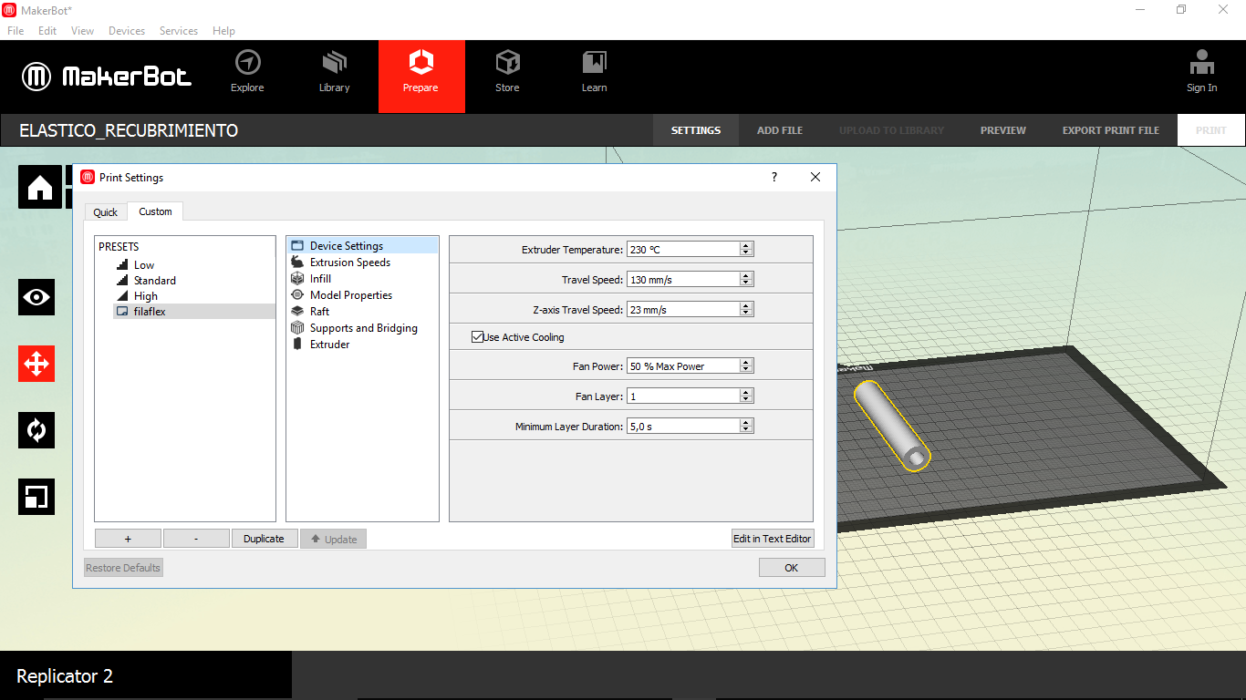
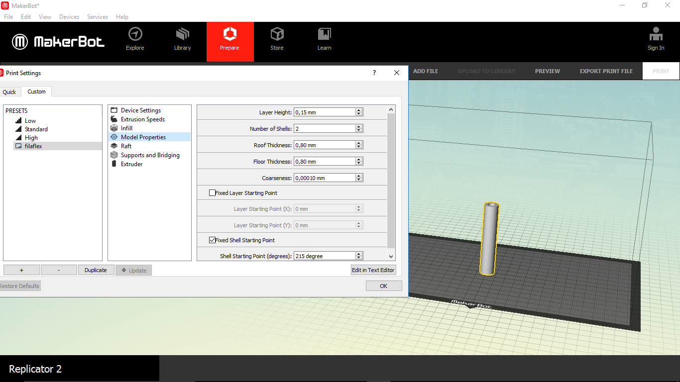
We thought that the system we have designed was going to give us a lot of trouble, but in the end it worked perfectly. Covering the rod with a PLA filaflex to gain more friction to pull the paper from the roll, the only adjustments we needed to do were the height of the inferior rod and its stabilisation. It took us more time to test it to see if it worked rather than building it (please take a look to 'Tests').
Covering With Filaflex The Motor Rod
First we did some tests. We needed to have an element that could keep enough pressure to keep the paper rolling, without twisting or breaking.
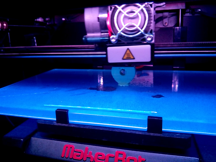
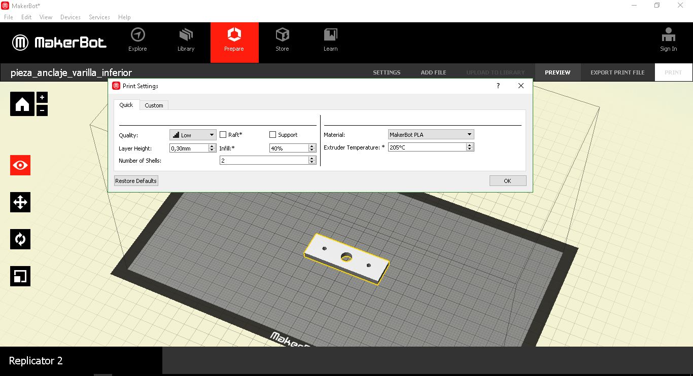
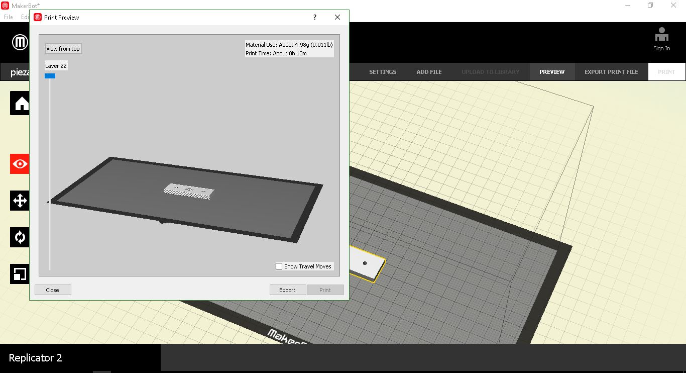
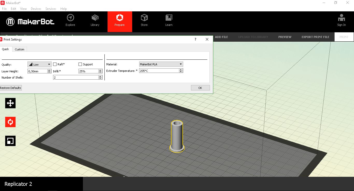
Printing
-
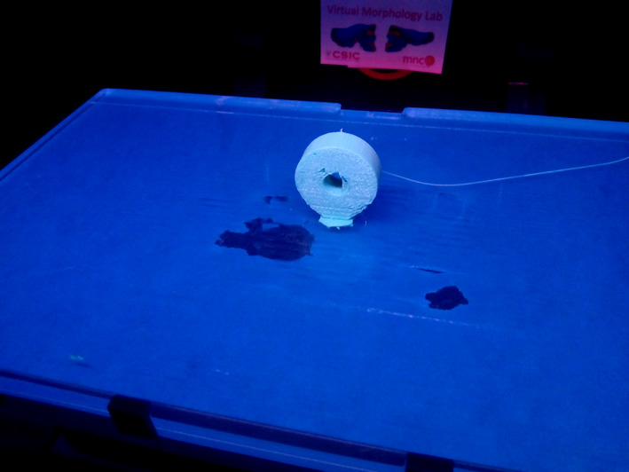
Printing
-
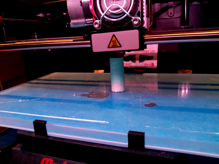
Printing
-
Printing
Printing
Calculating Height
Building it!
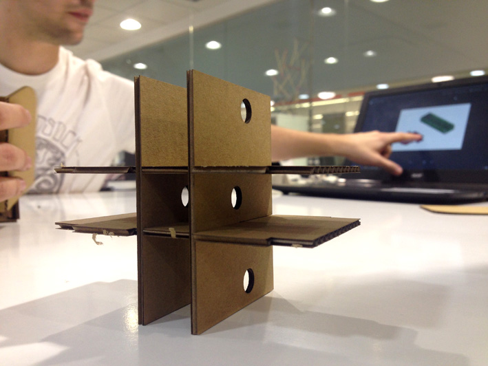
Having the 3D Printed Parts To Adjust And Hold In Place The Inferior Rod
Inferior Rod Holding Elements
-
Inferior Rod Holding Elements
-
Inferior Rod Holding Elements
-
Inferior Rod Holding Elements
-

Top View
-
Top View
-
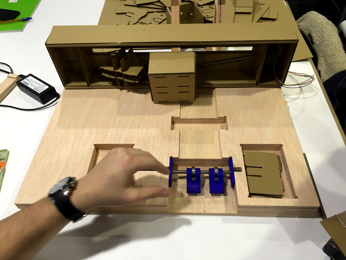
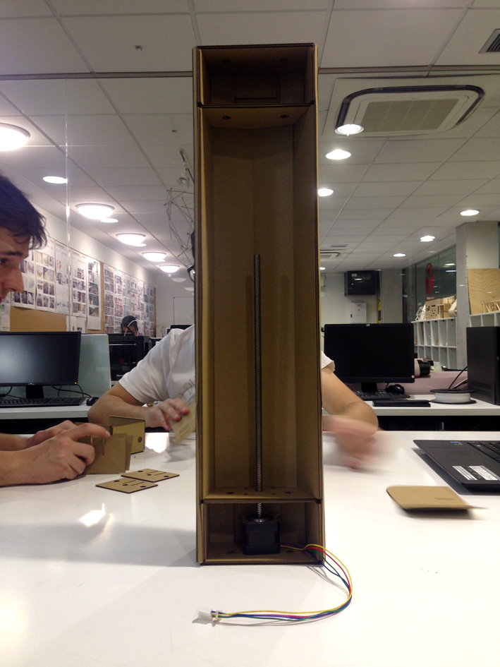
Putting Together The System
Now was the time to start adjusting the height of the inferior rod. Screwing the rod's supports to a 3mm Medium Density Wood and then directly to the 20mm Plywood, having at their sides a plastic plate to make sure the rod does not move while operating.
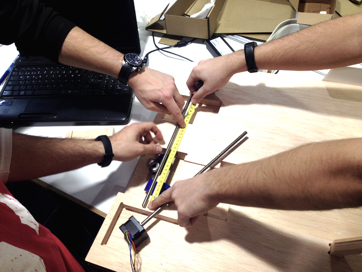
Measuring
Testing
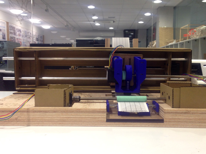
Front View
Zoom Front View
Adjusting the rolling system in order the paper to be pulled by the motor.
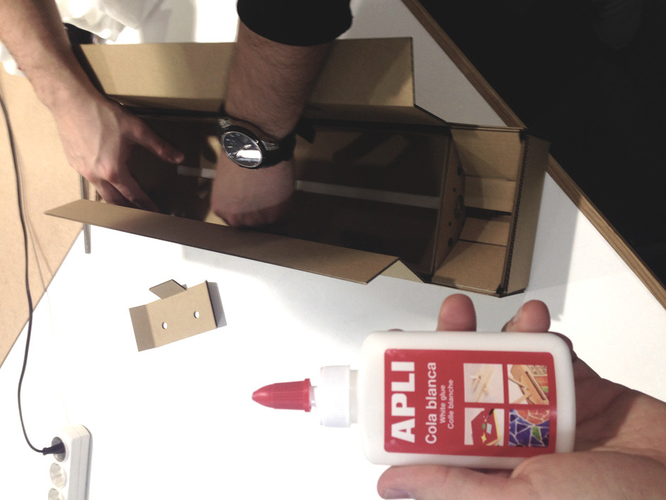
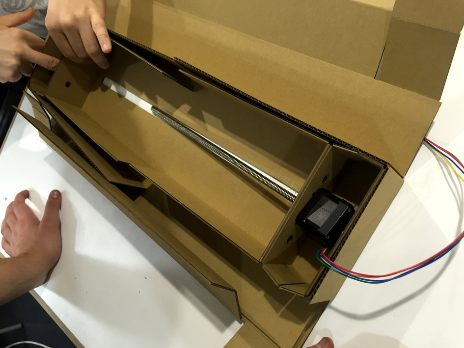
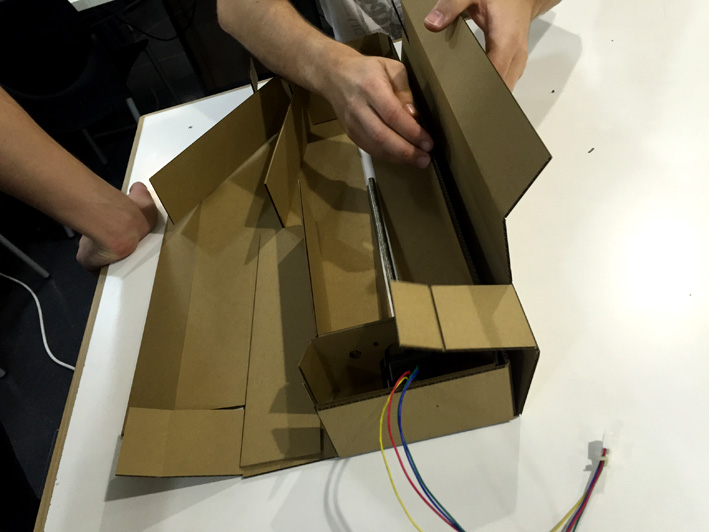
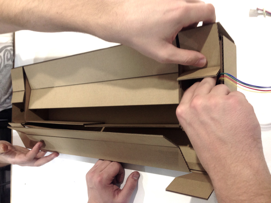
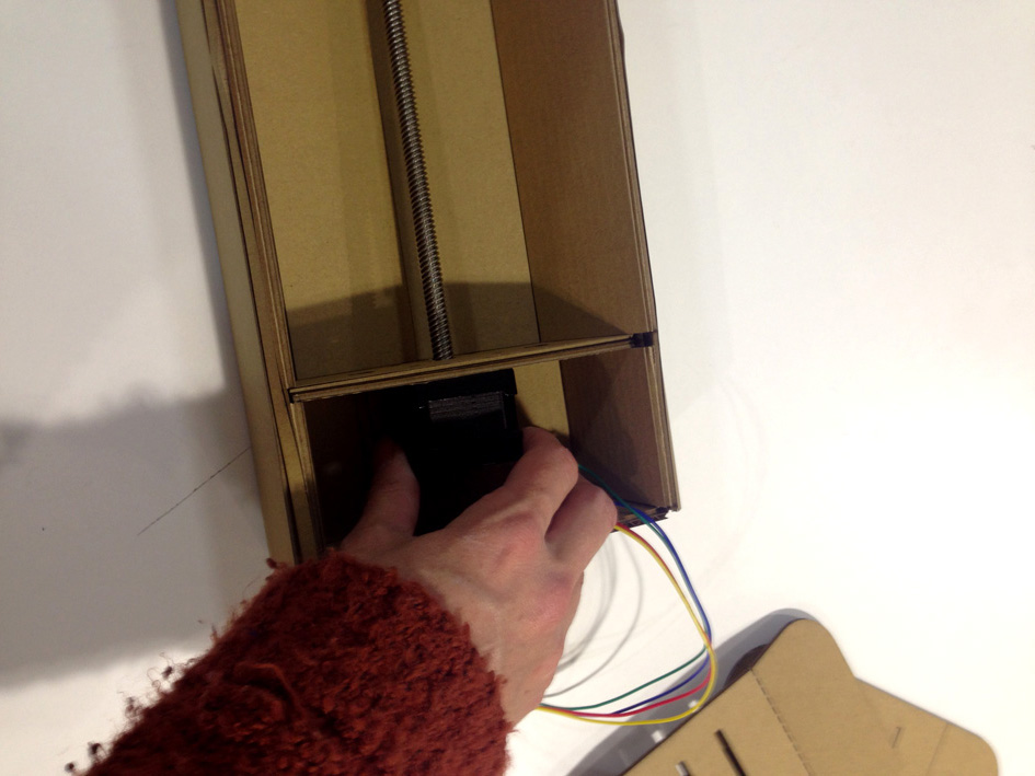
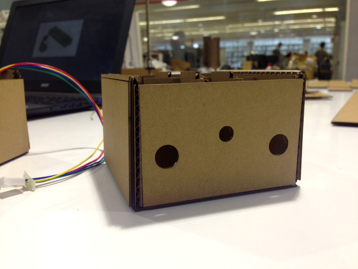
Building Our Cardboard Stage
3mm cardboard + lasercutter machine + readapted stage design + glue = OUR STAGE
Building The Stage
Building The Stage
Building The Stage

Building The Stage
Building The Stage
Building The Stage
Building The Stage
Building The Stage
Building The Stage
Building The Stage
Building The Stage
Building The Stage
Building The Stage
Building The Stage
Building The Stage
Building The Stage

Building The Stage
Electronics
FabAcademy Links To Websites We Have Used:
Fabacademy Website we had a look at:
FABACADEMY TUTORIALS:
http://docs.academany.org/FabAcademy-Tutorials/_book/week9_machine_building/gestalt_start.html
http://docs.academany.org/FabAcademy-Tutorials/_book/week9_machine_building/gestalt_ide.html
http://docs.academany.org/FabAcademy-Tutorials/_book/week9_machine_building/machine_resources.html
http://fabacademy.org/archives/2015/doc/MachineMakingNotes.html
GitHub Openp2design and Pygestalt:
https://github.com/openp2pdesign/wxGestalt
https://github.com/nadya/pygestalt
Fabnet
http://mtm.cba.mit.edu/fabinabox/dev/fabnet/overview.html
Installing Python and Pyserial:
https://learn.adafruit.com/arduino-lesson-17-email-sending-movement-detector/installing-python-and-pyserial
Machines the make
http://mtm.cba.mit.edu/machines/mods/index.html
http://mtm.cba.mit.edu/machines/science/
http://archive.monograph.io/james/m-mtm
Drivers:
http://www.ftdichip.com/Drivers/VCP.htm
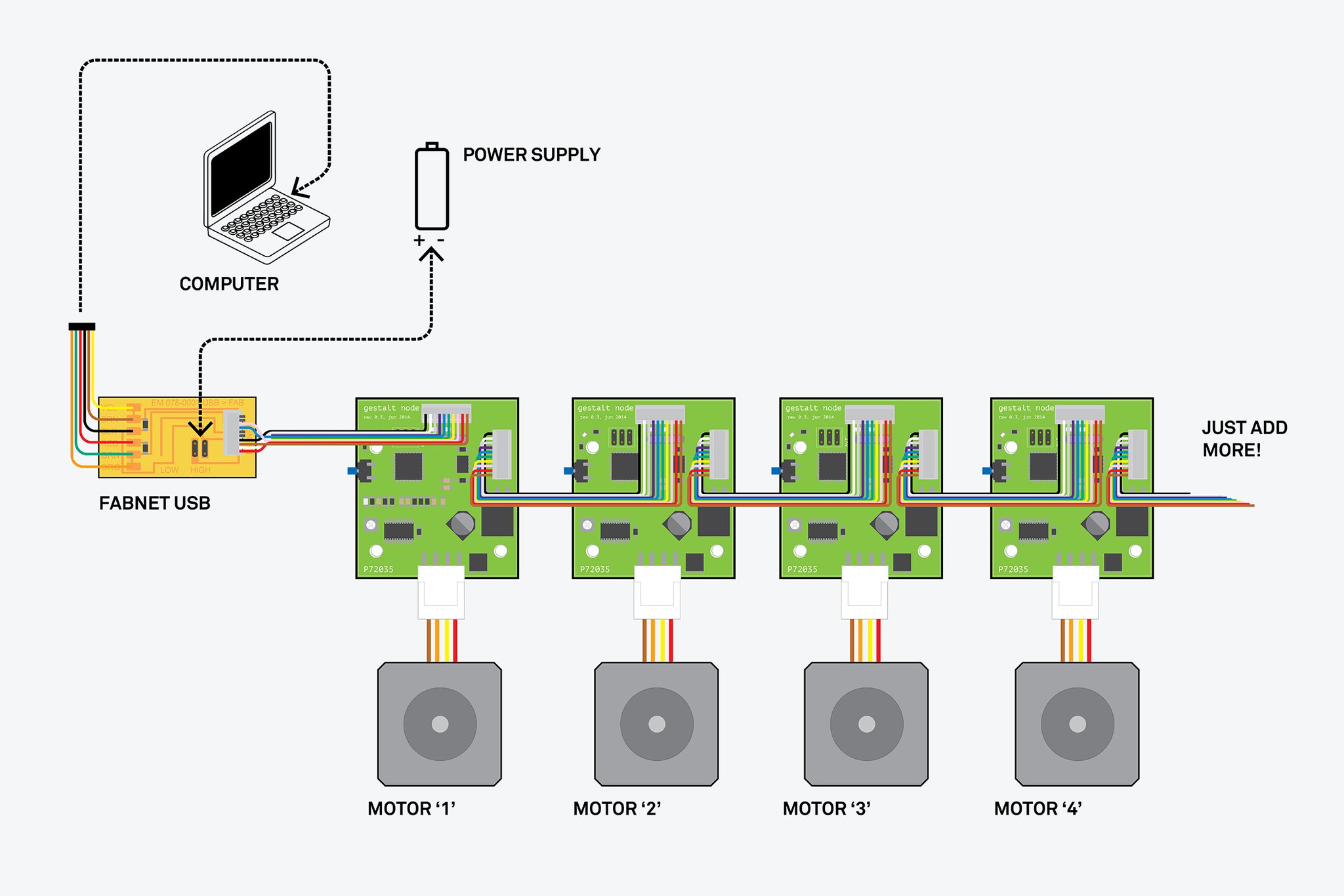
Putting Together The 3 Gestalt Motors We Need For Our Machine
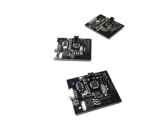
Nodes
-
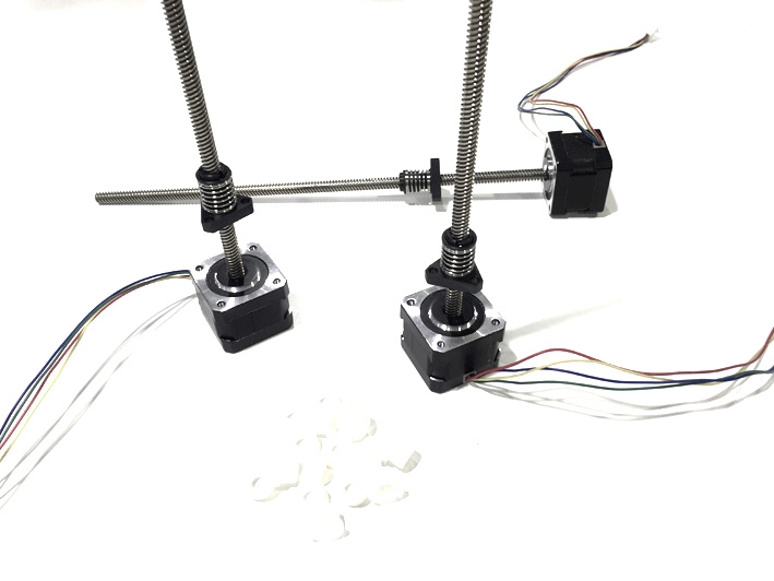
Motors
-
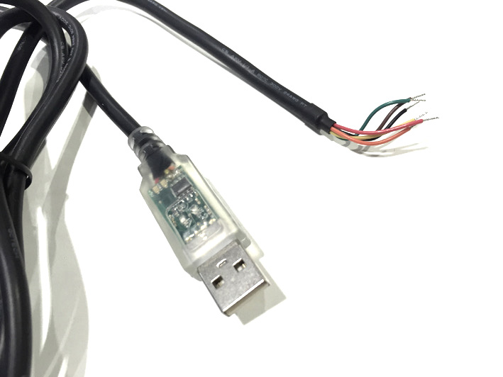
USB Cable To Fabnet
-
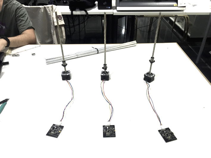
Nodes+Motors
-
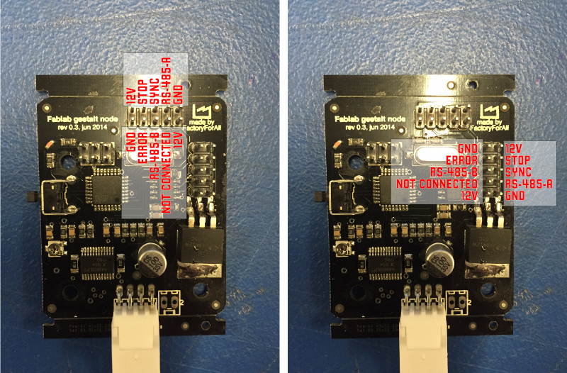
Connections
-
Connections
-
Connections
-
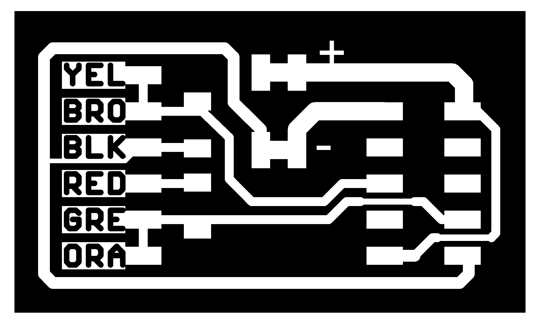
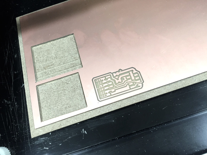
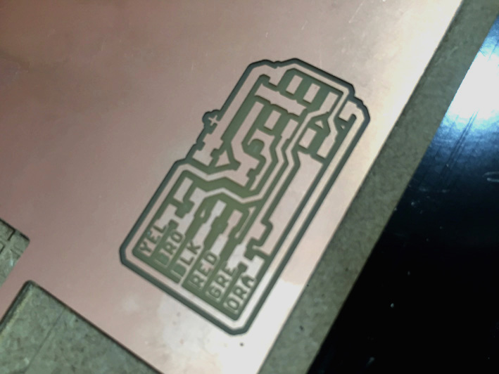
Milling Bas' Fabnet Board
Looking at the website reference, Bas' fabnet board was the one we decided to do. We looked at everything we needed to start with it.
Milling
-

Milling
-
Milling
-
Milling
-
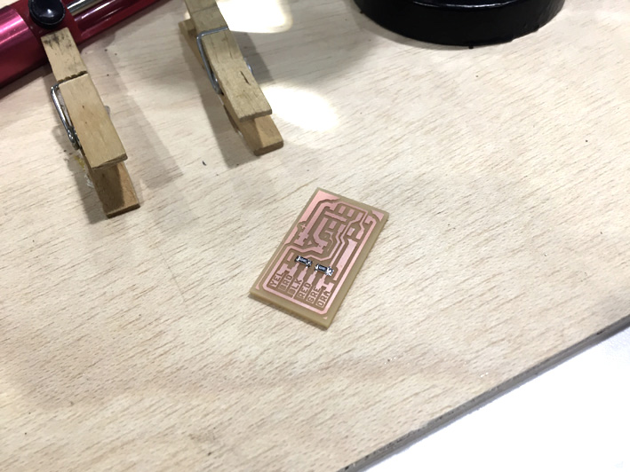
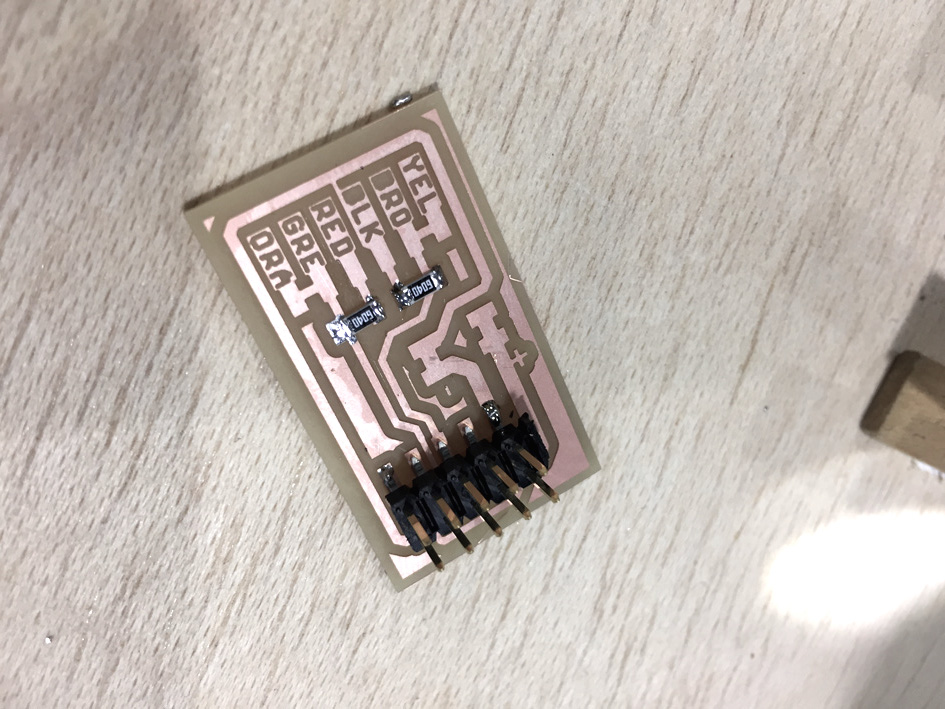
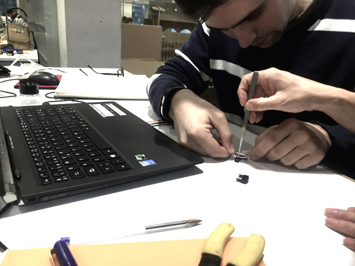
Soldering
-
Soldering
-
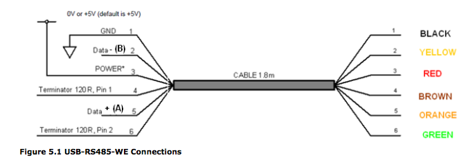
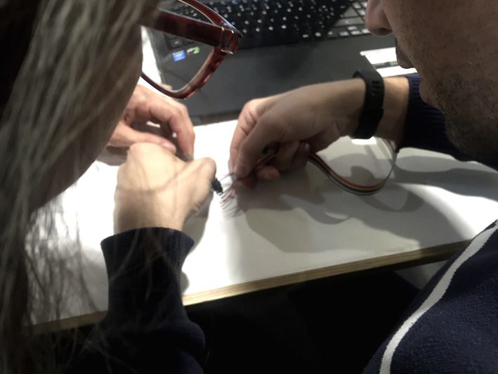
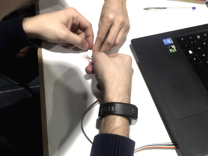
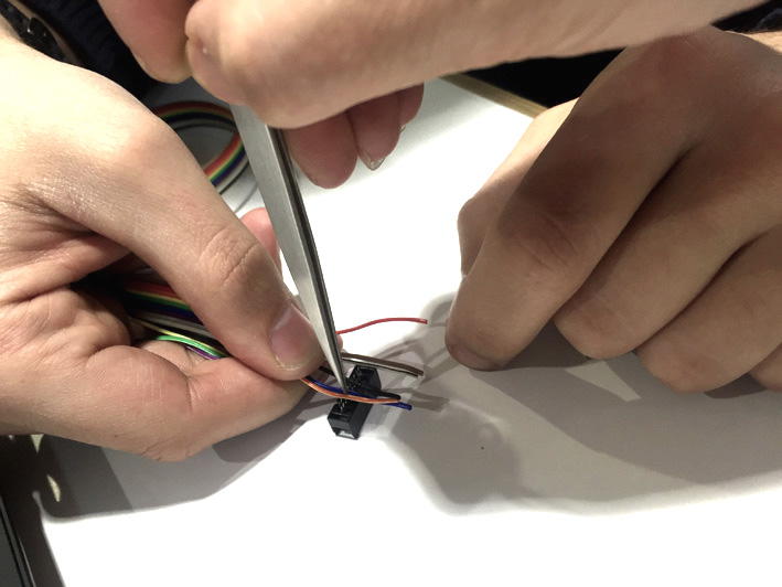
Problems With The Ribbon Cables
The cable that connects the fabnet to the motor node was not done correctly and that led us to nearly burn one of the nodes with a short circuit. Thanks to our instructor, we could recover that node.
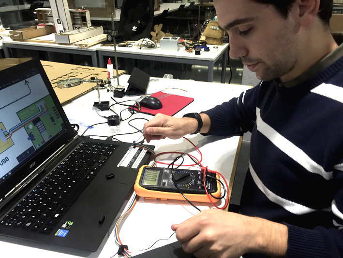
Cables
-
Cables
-
Cables
-
Cables
-
Cables
-
SOLVING PROBLEMS
Improvising As Design Did Not Come out As We Thought
Improvising as a part of the design process
During the building process, the design did not come out as expected and all kind of problems aroused. In one way or another, as time was not with us, we had to improvise and solve everything for it to work. In a near future, we can take into account all these problems and re-think the design for a better one, but for this first prototype, we solved as shown below:
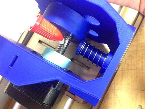
Problems in the head - rotary movement
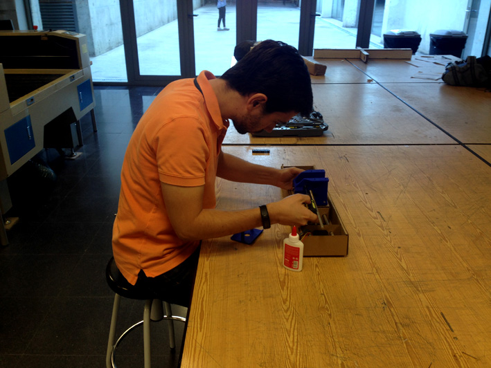
In the head mechanism, the screw inside the rotary object did not work as expected, having to improvise and use glue to fix it to a filaflex cylinder and the motor rod. It worked.
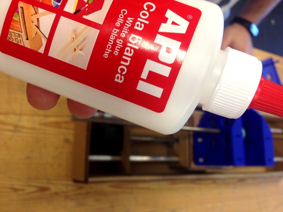
Gluing
-
Gluing
-
Gluing
-
Gluing
-
Gluing
-
Gluing
-
Gluing
-
Gluing
-
Gluing
-
Gluing
-
Problems with the height and stability of the stage
When putting together the whole machine, as the punch needed to be in a certain height for
punching (but not high enough for not missing the punch), adjusting everything for it to happen
was difficult. We used 3mm Medium Density Wood grouped together.
At first we thought it was working, but later on when punching the paper, the stage was not
strong enough to maintain the pressure on the paper.
Perforation Time!
-
Perforation Time!
-
Perforation Time!
-
General View
-
Problems with the height and stability of the stage v2.0 - Previous Solution Did Not Work
We had to make changes again. This time, instead of using screws to compress the cardboard into place, we used an attachment with an 'L' form screwed at the rear side of the stage. This solution is more simple than the one used before, and it worked much better.

'L'
-
Problems with the 3mm Cardboard
At one point, during the construction and de-construction of the stage, the
cardboard started to tear apart at the edges. As we did not have a lot of time left
(and creating a new stage was not an option at that moment), we really had to improvise
and use duck tape to stiffen the whole piece together.
Although aesthetically is not the best, functionally it worked correctly.

'L'
-

'L'
-

'L'
-
Problems with punching the paper
Once we had the machine built, we had a really big problem with the punching mechanism.
The machine was not making the hole on the paper. When the punch came down from the head to
make the hole on the paper, the force to do it turned into a backward movement for the stage,
failing to punch correctly. What we had to improvise is an additional structure to make sure
the head stayed in the same position in the vertical axes, providing horizontal movement while
working. It took time to decide what was the best improvised design. In the end, we added a 3mm
Cardboard structure to hold the header while punching the paper.
This is the new added element to hold the motor rod
New Added Head Holder
-
More Problems with punching the paper...
When we tested the punching mechanism again, we realised then that the force needed to make each hole was
excessive. After many tests done, the result were bigger holes than the ones we needed, making it more
difficult for the music player to do its job.
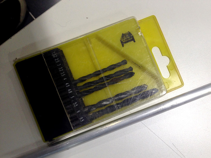
Then, we tested the machine with a new punch. This punch was done by sanding a screw with a radial saw,
having a less surface area and a sharpened end. As a result, the tests gave us finished holes with the
correct diameter for the music player with less effort.
The Spring
Related with the problem just above, another one appeared when the stepper motor from
the head still skipped steps when rolling the mechanism once we solved the problem with the punch.
Now, the spring forcing the shaft to go back up was the one making too much effort when being
compressed, causing the motor rod to stop moving and making the stepper to skip steps.
The solution to this was quite simple: cut the spring, making it shorter and reducing its
stored mechanical energy. Shorter spring, less force to fight against.

New Added Head Holder
-
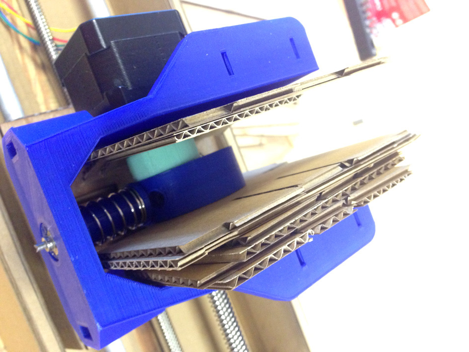
Problems Holding Down The Paper While The Punch Changes Position
The most important problems of the mechanical process were solved (rolling
the mechanism for the shaft to go down and having a punch in order to make the hole correctly).
One thing that we did not expected at all, was that once the paper was punched, the paper got
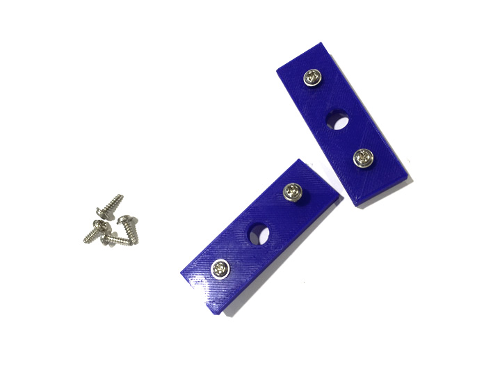
stuck with the punch, moving together up and down. What we had to do is a new part that was not
on the first design, to hold the paper down while the punch came back up to restart the whole process.
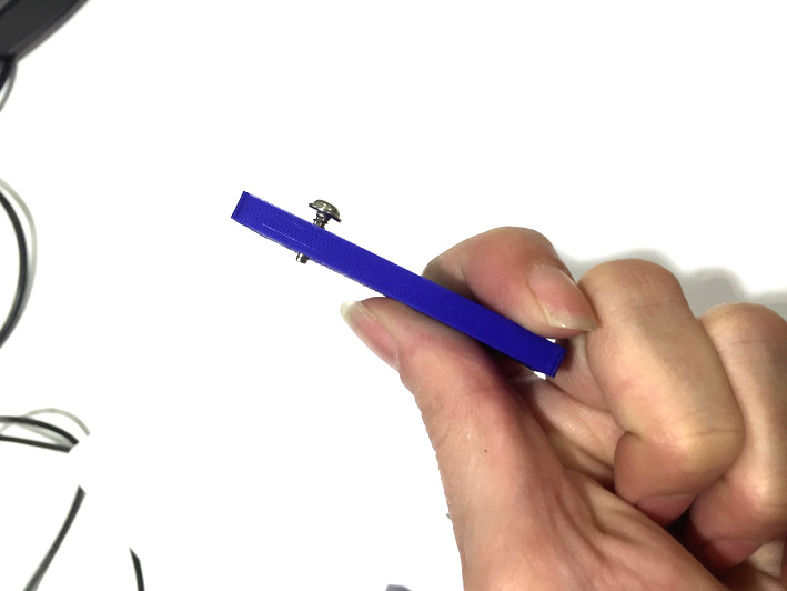
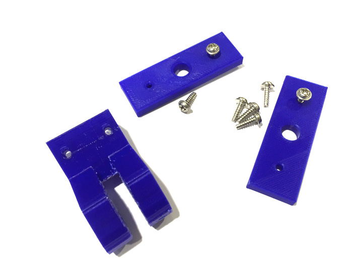
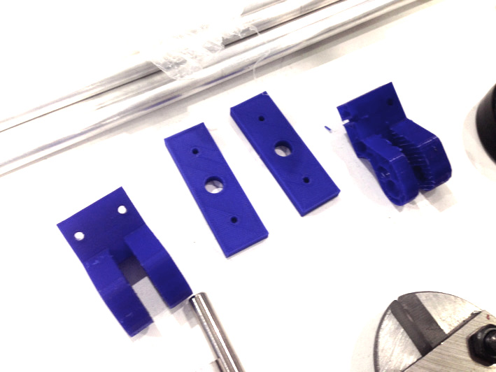
We did this by laser cutting two pieces of wood joined together, letting the paper to slide between both
pieces. The top piece had the job of holding the paper down when the punch came back up, and the bottom
piece had the job of making the hole correctly.

New Added Head Holder
-

New Added Head Holder
-

New Added Head Holder
-
More Pictures 'Improvising':
Improvising
Improvising
Improvising
Machines We Have Used
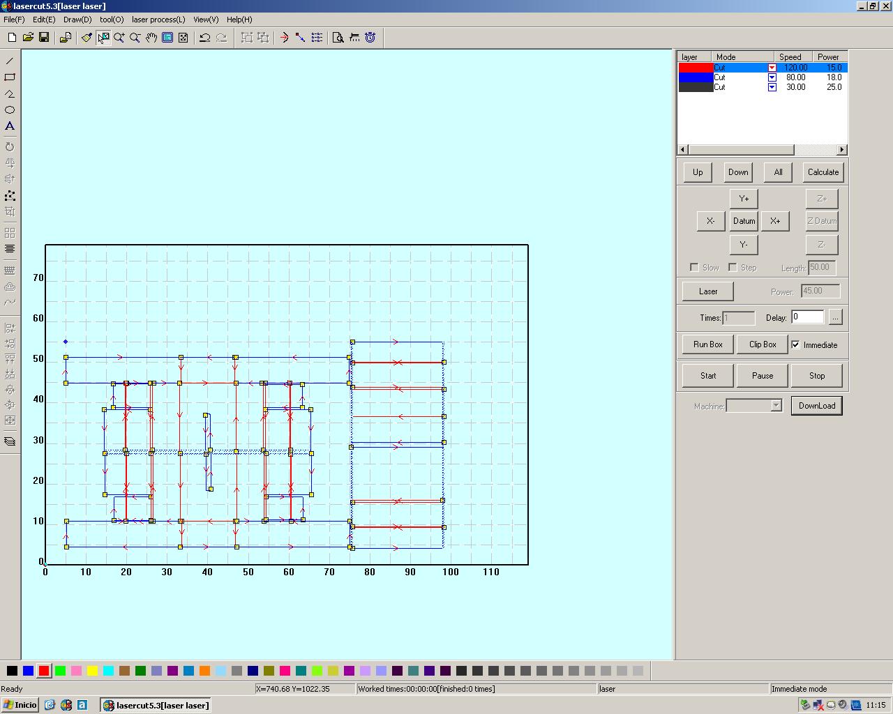
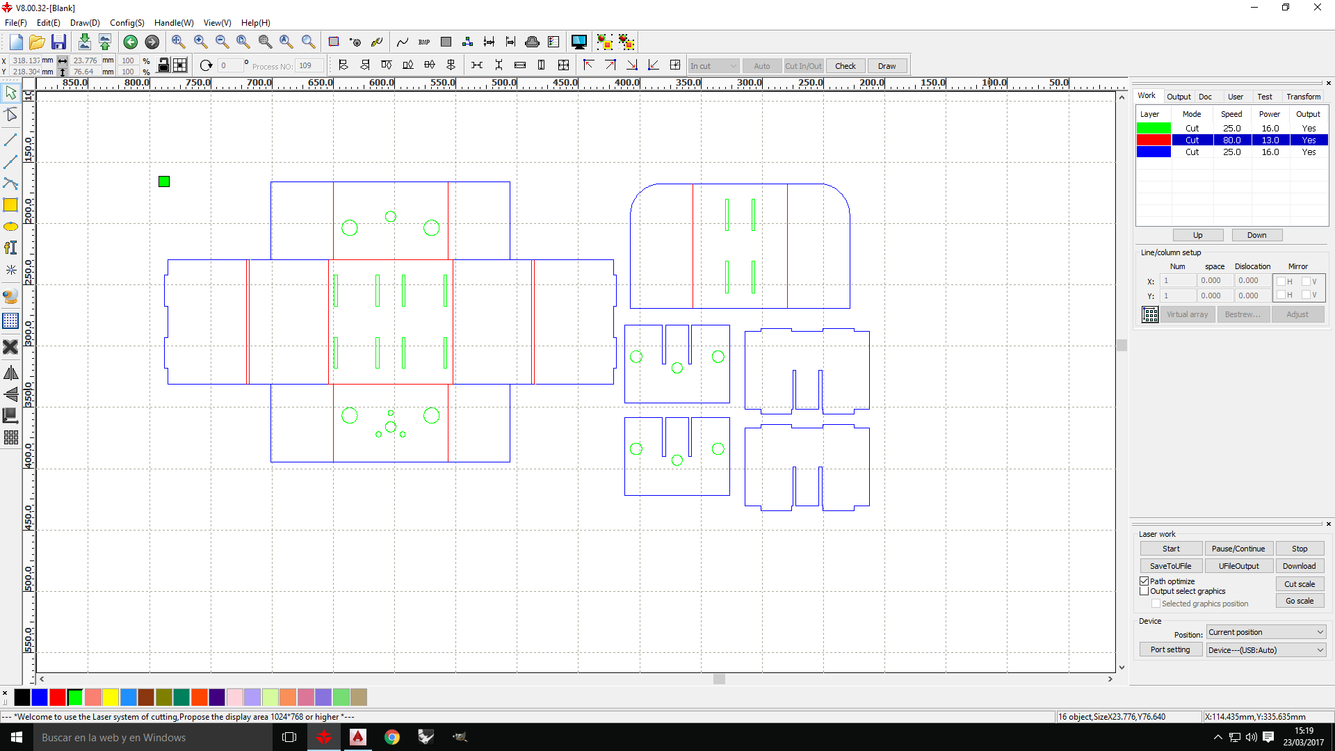
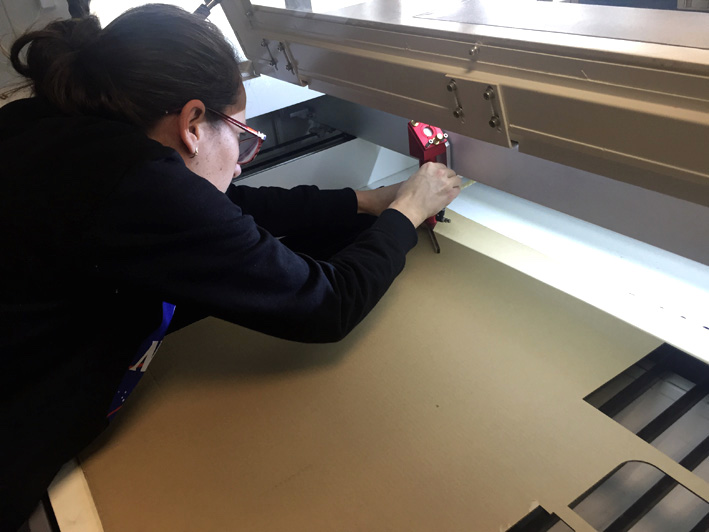
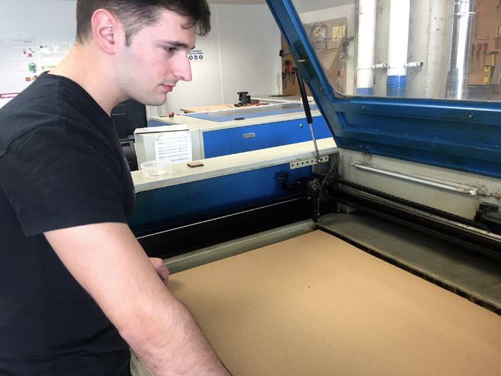
Lasecutter Machine
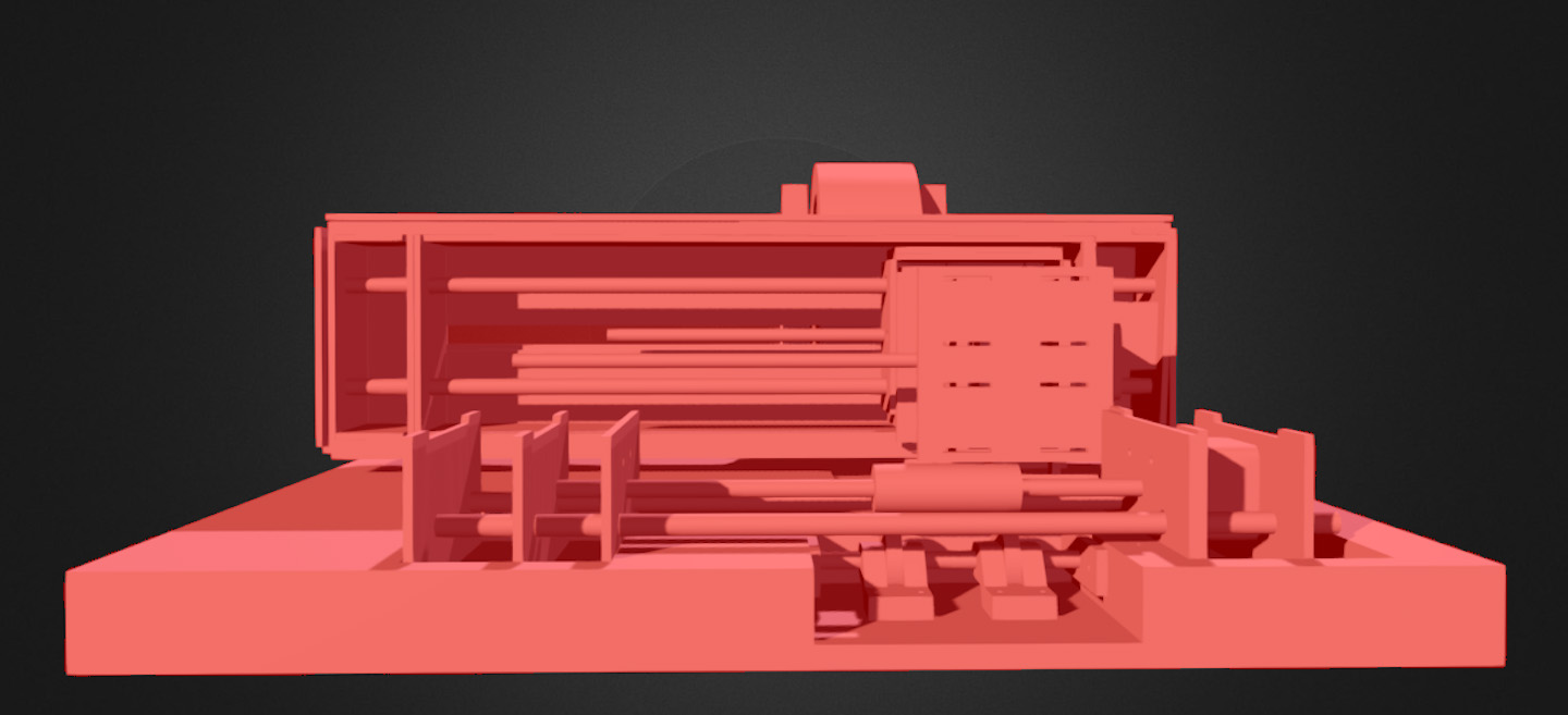
Render
-
Render
-
Render
-
Render
-
Videos Laser Cutting
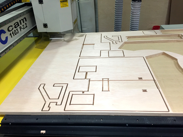
CNC Machine
We had a 20mm thick Plywood where, with a CNC machine cut everything we needed. The final dimensions of the base were 562x500mm.
CNC Cutting
CNC Cutting
CNC Cutting
-
Video With The CNC Machine
3d Printer
Render
-
Render
-
Render
-
Render
-

Render
-

Render
-
Render
-
Render
-
Render
-
Render
-
Render
-
Render
-
Render
-
Render
-
Render
-
Render
-
Render
-
Render
-
Render
-
Render
-
Render
-
Render
-
Modela MX-20
Render
-
Render
-
Render
-
Render
-
Milling the Board!!