3D Printing
This weeks lecture was all about 3D printing and 3D scanning. Neil began with a brief history on 3D printing and how its a pretty old technology which originated in MIT. Today it has gained momentum with the cost of the printer coming down and maybe the introduction of DIY 3D printers.
3D printing is the process of making 3D models from a design file. Similar to printing 2D designs onto a paper here we print 3D designs. The most common technique is the fused deposition method. This process of making 3D structures is called additive manufacturing.
Fused deposition method uses primarily plastic, which melts upon heating and settles when cooled. The plastic will be heated first and then extruded out as beads which will be deposited layer after layer to form the structure. Some limitations of this technique is low resolution, long printing time etc.
What I did.
- Printed out a standard test print. This have various cases which test the limits of the printer.

The shapes included in the design are
- Nut, Size M4 Nut should fit perfectly
- Wave, rounded print
- Star, Sharp Edges
- Name, Complex Shapes
- Holes, Size 3, 4, 5 mm
- minimal Distance: 0.1, 0.2, 0.3, 0.4, 0.5, 0.6, 0.7 mm
- Z height: 0.1, 0.2, 0.3, 0.4, 0.5, 0.6, 0.7, 0.8, 0.9, 1.0, 1.1 mm
- Wall Thickness: 0.1, 0.2, 0.3, 0.4, 0.5, 0.6, 0.7 mm
- Bridge Print: 2, 4, 8, 16 mm
- Sphere, Rounded Print 4.8mm height
- Sphere Mix, 7 mm height
- Pyramid, 7 mm height
- Overhang: 25, 30, 35, 40, 45, 50, 55, 60, 65, 70°
- Warp, does it bend?
- 3D Print Font, optimized for 3D printing
- Surface, Flatness
- Size, 100 x 100mm x 23.83 (10mm width)
- Spike, minimum Layer Time, 21 mm height from Bottom (include Base-plate)
- Hole in Wall, 4 mm diameter, check for proper print
- Raft Test, raft should be just under the model
- Retract Travel, check retract settings for longer travel
By observing the printed object, the problem/limitations in the printing are:
The minimum gap which is visible is of .5 mm width. Gaps with less than .5mm is not possible.
It printed only three walls with width as 0.5mm,0.6mm,0.7mm. Walls with width less than 0.5 mm is not printer.
These are the major limitations i found. The others are fine but doesn’t have a very high resolution. It has some issue with sharpness for complex shape.
- This week we have to design and print some object which cannot be made subtractively. For this activity I choose to make a chain structure with round chain links one inside the other. As these are one inside other, it cant be subtractively manufactured.
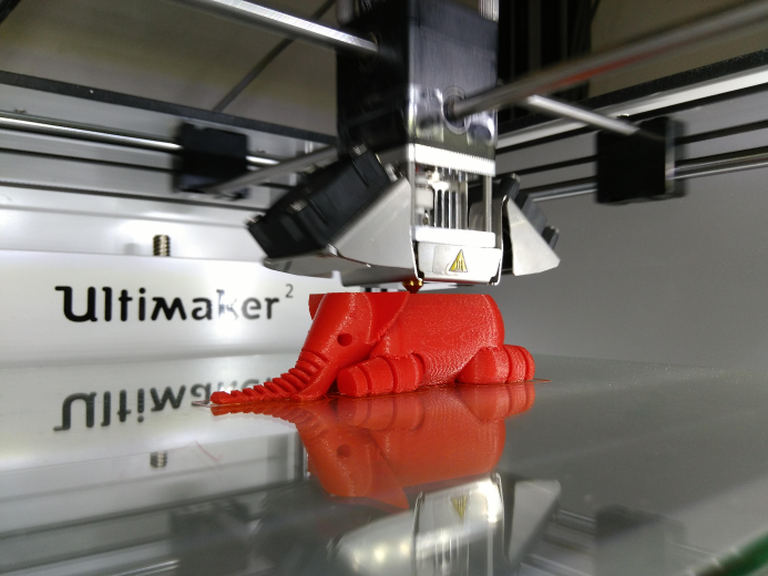
Till last week I used antimony for 3D designing. As it is too buggy i switched to an online - easy to use- design tool called Tinkercad. There is an option to download the designed file as .stl. The downloaded stl file ws opened in Cura and converted ti to GCode, which can be fed directly to the Ultimker, which is one of the printer we have in our Lab.


Here are the Design Files
3D Scanning -
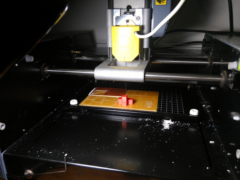
3D scan using Modella R.A.P.S
Modella can be not just be used for milling boards and wax, but also to scan objects. For this, the end effector have to be changed to a special piezo enabled needle head. It will go around the area and probe to find obstacles/surfaces. So you can imagine how slow it is, goes around and probe in the space till it reach a surface.
The software used here is Dr.Picza. I have restricted the scanning area to the vicinity of the object to be scanned, which can dramatically reduce the scanning time. I also limited the maximum Z value. 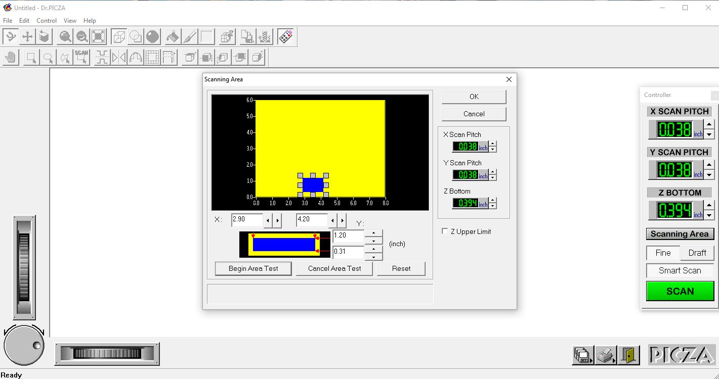
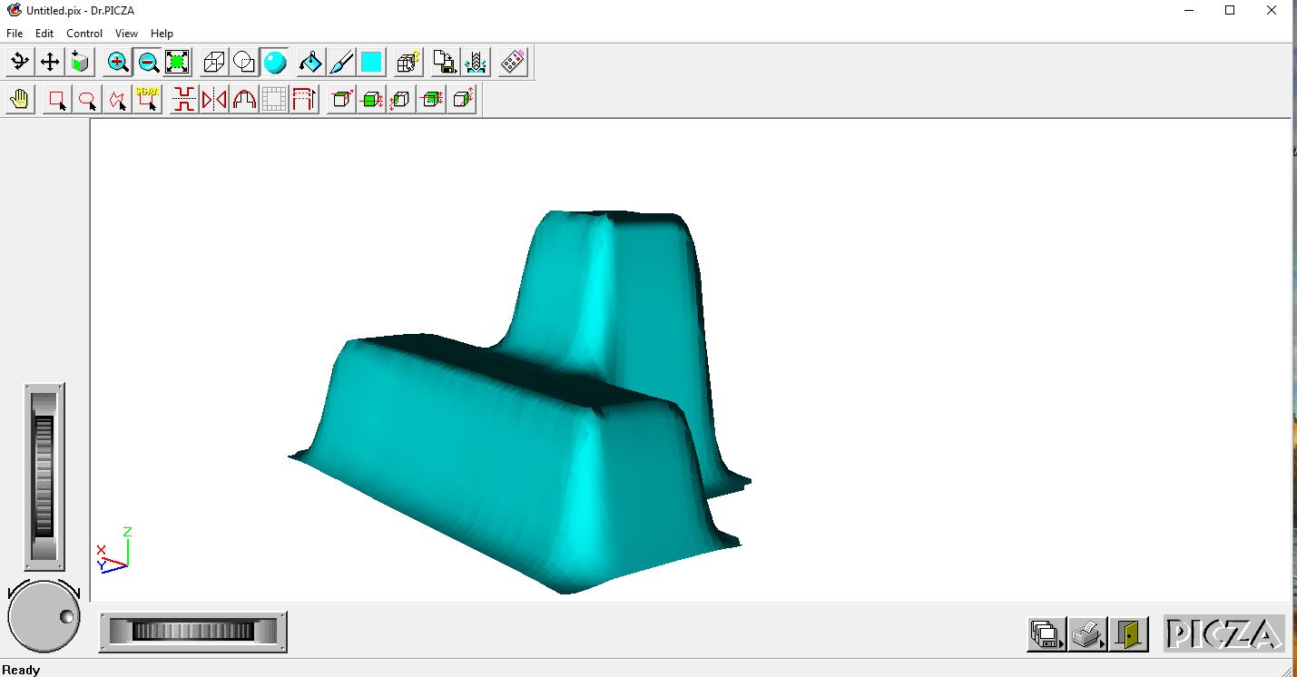
Here is the design files
Milk scanner
In our lab the most used scanner is Kinect followed by Rolland and 123D Catch. So as a group project, I along with Sibu and Yadu are trying to make a opacity/fluid scanner. As the requirement is an opaque liquid, here milk, we are planning to use a the fabric paint available in the lab, hoping that it could satisfy the needs.
It took us some effort to get all the things ready for scanning. With the things lying around in the Lab we made the Fab Milk scanner. We got the idea of doing such a thing from here. Further research got me at the instructables page. Unfortunately the description is quite confusing. So we had many doubts like
- Can we use any other liquid other than milk.
- Is there a fixed height for placing the camera.
- Is there a fixed rate at which the liquid has to be poured etc.
So with lot of uncertainty we started our experiment. Diluted the fabric paint (blue color), placed the camera(a webcam) vertically above the tray in which we have fixed three different figures for scanning. We had 3 cone like objects.

As I said earlier we were following the instructables website, we used software developed by them for getting the displacement map.
- Here we faced the fist road block. The software was windows only compatible so had to configure everything in another computer which had Windows installed.
- The next problem we faced was that we didn’t have even light distribution for our scanning setup. Solved it by having an external light source(a table lamp) and after trying different positions, finalized on a position where we get the best illumination.
- The interface of the software are minimal but adequate. Was a little hard to figure out the actions. The order is like this
- capture the pictures by pressing space once and end the capturing by pressing space again. Start and stop pouring the liquid you are using, here it is paint, simultaneously.
- save the files next. There is a handsome amount of processing to be done after that, so be patient. It will take some time, depending on your PC.
- The saved file has .xml extension. You can import it as a displacement Map in Blender or Maya or any other Application that uses Displacement Maps. The original source prefer something called MovieSandbox. I tried it but not at all user friendly if you are not from design background.