Fab ISP
Neil went through all the areas for electronic production which included making a PCB, soldering the components properly etc. This week I will be milling out one, and soldering components on top of it. Neil has adviced to make the ISP which will be of use in the future.
We started off by downloading the Electronic Production assignment file form Fab academy 2016 archives. We chose to mill the HelloISP board designed by Neil. Opened it in Antimony got the Trace.png and Outline.png.
Now move onto the machine. Switch it on. Change the bit carefully to 1/64 or 1/32 for milling the traces or cutting out the board. Using the Fab Module move the head to the point where you want the origin to be. Then correct the height of the bit, shift it to a position where it is just touching the surface.
We download two files for making the PCB, trace and cut. Trace png will have all the traces of the components and cut will have the cut line for cutting the PCB from the plate.
NOw open up fab modules and select input as image (.png) and output as Roland MDX-20 mill (.rml) and after clink on make_png_rml.

A new window will be opened with mainly three fields, from:png, to:path and to:rml.

- from:png
Click on Open button and select the traces.png file. As we are going to mil the traces first we will choose the bit, situated at the top, as 1/64.
- to: path
Here we can fine tune the milling but usually you can stick with the defaults itself. Th only change I make when i have curved traces, then i change theerror(pixels)to 0 or .5 from the default 1.1. This parameters controls the segmentation of lines while making path, lower the value more number of segments which makes smother cuts. After having the settings ready click onmake .path.
Now in the Fab Modules give make .rml command and then send it to modella. Wait till the work is done. - to:rml
Here we have the controls for position of the head of modella. Move it to required position and note down the coordinates. Change the bit carefully to 1/64 or 1/32 for milling the traces or cutting out the board. Then zero the z axis by loosening the bit from bit holder and slowly lowering it till it touches/ests on the surface to be milled. After this click onmake .rmland thensend it!which will open a new and final window where you just select begin milling after cross checking all are correctly set.
After cutting the traces change the bit to 1/32 and repeat the process using Fab Modules using cut board .png file. This will make a cut around our circuit so that we can remove it from the larger board.

Note: Be careful while removing the board as their are chances of damaging it.
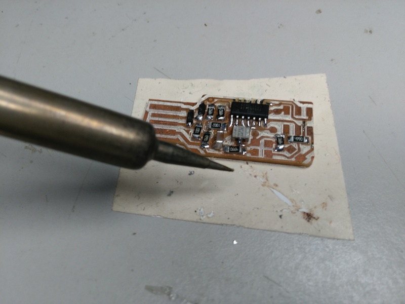
Now as we have the board, it’s time to start soldering the components to it. As a good practice, Franc told all to write down the components in a paper/book and draw a box corresponding to each component. Then we took the components and placed them in their corresponding boxes. This way we won’t mix up anything and it,s easy to solder as the components are kept handy.
Soldering
Now as I have milled the board the components have to be soldered on to it. Soldering is the process of fixing the components over a PCB and one can imagine it similar to welding. The prerequisites for soldering are
- Solder
Solder is an alloy which comes in spools or in tubes. It is the one which attaches the component to the board. When heated solder will melt and can bond to the contacting surface. There mainly 2 variety of solder the traditional one with lead and tin as the base metals and the recent ones which is lead free. In our lab we have the lead free variant. The one with lead will cause health issues if exposed for a long time. - Soldering iron
The soldering iron consist of thewand,tipandstand. The versions with temperature control will have one more part namedbase. Tip is the part of the iron that heats up and allows solder to flow around the two components being joined. This is the art which transfers the heat to the surface to be soldered and thus melt the solder and apply it evenly. Usually tip can be replaceable. In our lab we haveconicaltips.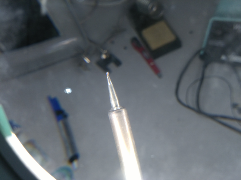
Base is what is left after you remove the tip from the iron. We have to hold it in our hand similar to holding a pen. It is sophisticated piece which has to transfer heat to the tip as well as prevent it from reaching the hand.! - Stand
This is a holder for placing the iron when not in use. Make sure that you keep it always in the stand as un attended ones can be hazardous due to the temperature. - Base
As I mentioned earlier, this is part which comes in high end machines which needs control over temperature. Some can even save temperature profiles and swiftly change between them.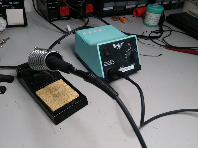
After soldering we have to check under the magnifier if the connections are proper and if time allows, do a continuity check too.
Programming the board
The prerequisites for programming your board are
- latest version of avrdude
- a mini USB cable
- the firmware of the board
When you have all the above try to flash the Firmware into the board. After extracting the firmware open a terminal at that directory and execute the following commands
make cleanmake hex: If you are using an Atmelice isp make that change in the makefile [change to atmelice_isp]. If you are using USB tiny then change to that.
sudo make fuse: initially it may show some error. But try it multiple times and you will probably succeed.sudo make program.
After doing all the above without any error messages popping up, your board should be programmed to work as an ISP.