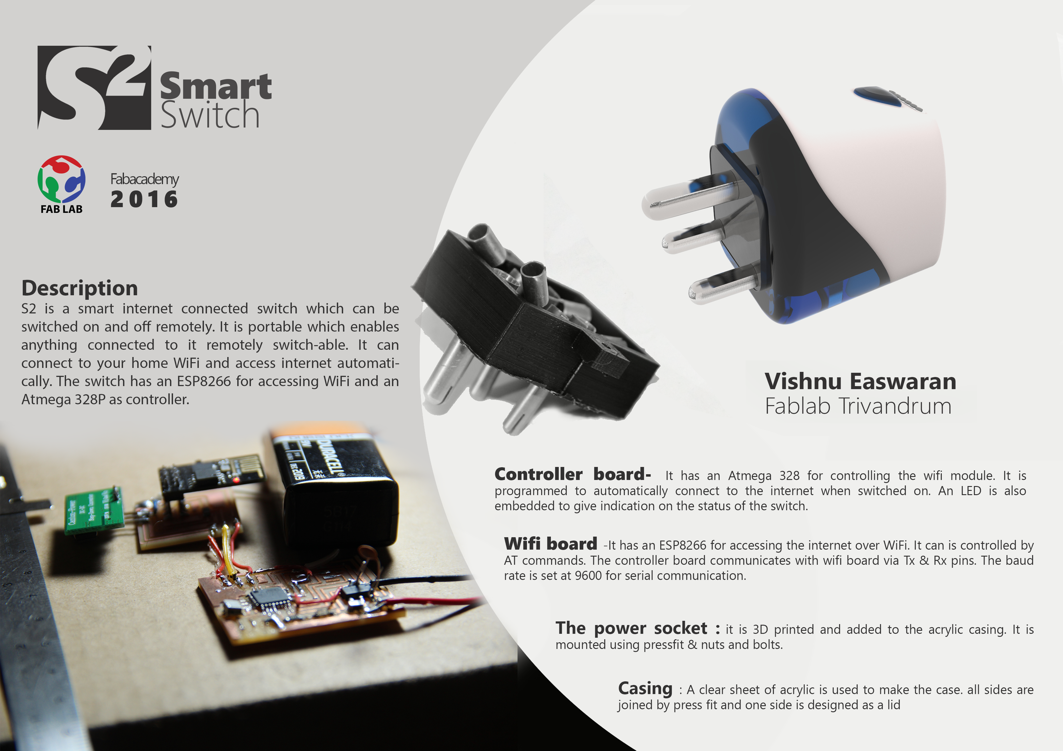
Smart Switch - S²
Since week 1, the week when we pen downed the idea, we have learned a lot. We gained knowledge of almost all aspects of product development, from planning, designing, electronic production, mechanical design etc to its ownership and legal matters. The coming two weeks we will be indulged in applying all these to develop our project. You can see the plans, expected timeline here.
I started off with outlining the work and dividing it into small chunks. These are what I came up with
- Learn about ESP8266.
- Look how to control the ESP externally using a microcontroller
- design the switch’s structure.

I will divide each of my development into different chapters for easy classification.
Chapter: ESP8266
I have heard from numerous people about he compact and affordable WiFi module but haven’t worked with it once. So i had to start from scratch. Their are a bunch of online forums discussing and developing on ESP but they all seemed to be ambiguous and incomplete. My idea is to
- have the ESP just for accessing a WiFi
- use an external mmicrocontroller to control the device
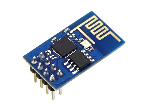
When you look into the details, you will see that in the short span after its first appearance itself it has iterated number of times to form new, better refined versions. The list begins with ESP 01 and goes on till ESP 14, totally 16 boards. You can also see a lit of other derivative development board based on ESP in the market. Please have look at the wiki page for finer details.
The general/minimal features of the board are
- 32-bit RISC CPU
- 64 KiB of instruction RAM, 96 KiB of data RAM
- External QSPI flash - 512 KiB to 4 MiB* (up to 16MiB is supported)
- IEEE 802.11 b/g/n Wi-Fi: most have integrated antenna
- minimum 2 and max 20 GPIO pins
- UART on dedicated pins, plus a transmit-only UART can be enabled on GPIO2
Yeah, thats right it packs a punch !!
As we don’t have any ESP in our lab, i ordered one ESP8266-01 and 12E for playing with. But you can see the problem here is it has a good processor within itself, and most of the online info is for making use of that to program and control the board. But that is not what I need. I need a separate controller to control the ESP.
To start with accessing the modules, we can use AT commands serially transmitted to the ESP. You can get the list of AT commands here. Neil have also listed them with some good examples in here too.
After I got the ESP I started to test it by trying to communicate with it. ESP works in 3.3v and draws huge amount of current, even up to 300mA. So first I have to make a stable power supply for ESP. If you are going to ignore this, you will find your ESP restarting randomly. I had a 3.3v,1A buck with me and I used it to power the ESP. The buck was given the power from a FTDI(5V) cable. The pin diagram of an ESP-01 is 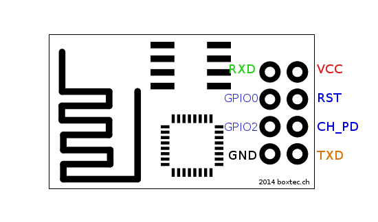
Here the you have to connect the VCC and GND to that of the buck and Rx and Tx to that of FTDI cable. Make sure both the FTDI and ESP have common ground. For enabling the ESP connect the chip power down (CH_PD) to 3.3v.
Now connect the FTDI cable to your PC and open a serial monitor for communicating directly with the module. The default baudrate was 115200 in my case. Check different values till you are connected. when initialised or switched own you will notice a few strings shows up in your serial monitor and finally declares initialized. If you see anything else chances for wrong baudrate and/or powers upply is not stable. Also make sure that CR,LF line ending are enabled while sending the commands.
Some of the handy AT commands are
ATwhich replysREADYAT+RSTwhich restarts the moduleAT+GMRwhich will return the firmware versionAT+CIFSRwhich gives the current IP address of the ESPAT+CIOBAUD=<baud rate>which can set the baudrate. make it accurate enough for the interfacing board. I changed mine to 9600.AT+RESTOREthis will restore the factory settings. This could be very useful if you somehow end up not knowing what all changes you made and is messed up.
There are more commands which you can try out. Try to connect to your Wifi, try to setup TCP/UDP clients and server. After juggling with the commands you will become familiarized. Once all the errors where sorted out and the communication stabilized I moved to the next step. NOte that completing this chapter alone took me 4 days, so don’t take it lightly.
Chapter: Communication
I decided to use Atmega 328P as the controller. It has dedicated USART pins for serial communication. I will make use of it talk with ESP. After fixing on that I began searching a protocol to communicate over the internet. Since my project works over internet, i have to follow certain protocols for communication and it is not easy as transmitting and receiving serially. The protocol is called Internet protocol or simply IP. 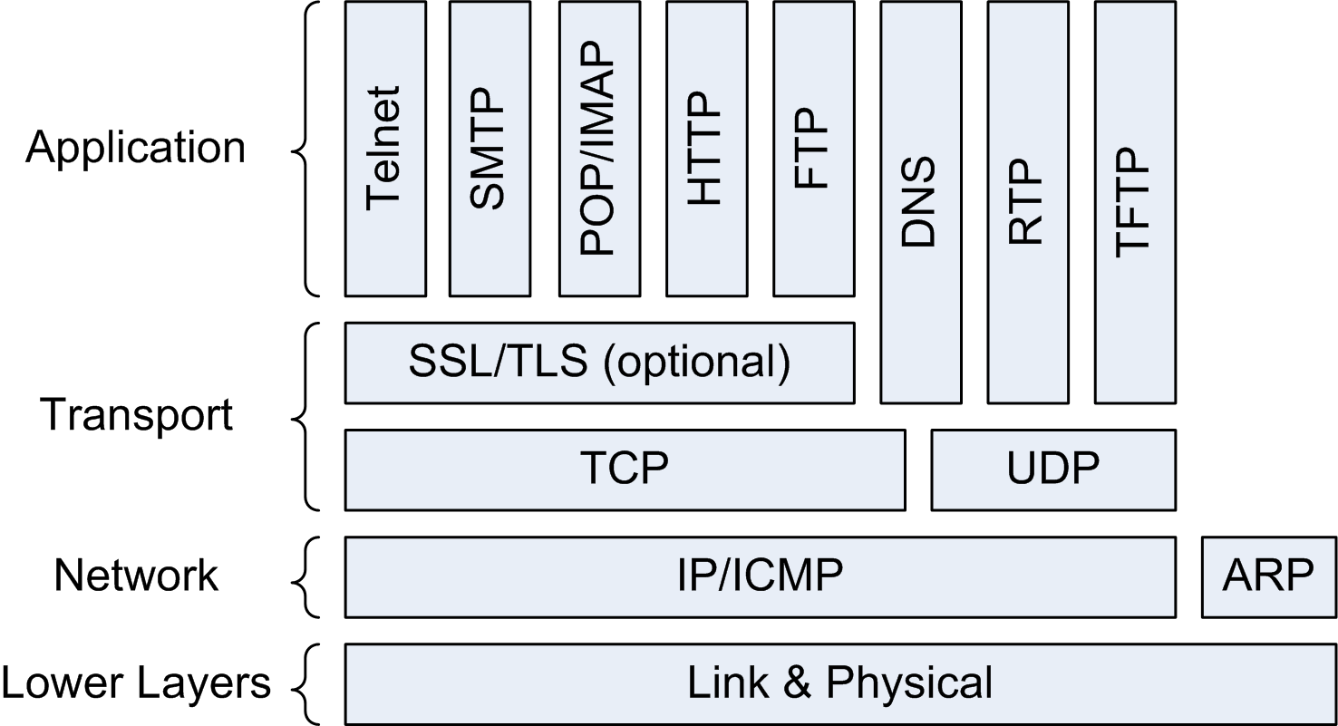
You can look here for explanation on basics of networking. This could be of help if you are unfamiliar to the domain.
Thinking in the line of an IoT device i thought why not try out a IoT protocol for communication? If I am aiming to have the project in the IoT category I should aply its protocols too right? So I decided to delve into that topic.
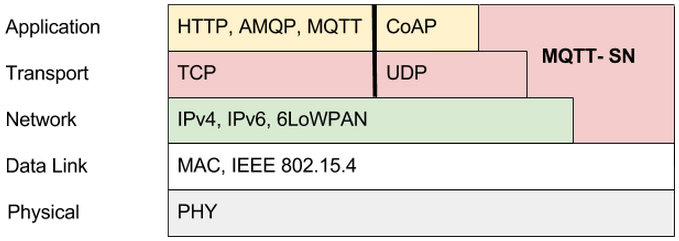
When I started to look around and I almost ended up with MQTT every time. It is can be described as
“MQTT stands for MQ Telemetry Transport. It is a publish/subscribe, extremely simple and lightweight messaging protocol, designed for constrained devices and low-bandwidth, high-latency or unreliable networks. The design principles are to minimize network bandwidth and device resource requirements whilst also attempting to ensure reliability and some degree of assurance of delivery. These principles also turn out to make the protocol ideal of the emerging “machine-to-machine” (M2M) or “Internet of Things” world of connected devices, and for mobile applications where bandwidth and battery power are at a premium.”
Sounds great right ? I also chose o try out the same for the project. For MQTT the work flow is described with Methods. MQTT defines methods (sometimes referred to as verbs) to indicate the desired action to be performed on the identified resource. What this resource represents, whether pre-existing data or data that is generated dynamically, depends on the implementation of the server. Often, the resource corresponds to a file or the output of an executable residing on the server.
- Connect:
Waits for a connection to be established with the server. - Disconnect:
Waits for the MQTT client to finish any work it must do, and for the TCP/IP session to disconnect. - Subscribe:
Waits for completion of the Subscribe or UnSubscribe method. - UnSubscribe:
Requests the server unsubscribe the client from one or more topics. - Publish:
Returns immediately to the application thread after passing the request to the MQTT client.
My plan is to run a MQTT client in a local server setup in Raspberry pi and then access it through the Static IP of our internet connection. The microcontroller will listen (subscribe) to a topic run in the Rpi server. For this first i have to have the following Things
- ESP as wifi access device: For this, after hours of research came across the Wifiesp. It is an arduino library fo having ESP connection similar to connecting to a WiFi shield. This wss a crucial part in communication as I was left in the dark as most of the already existing help was for directly programming the ESP, but my need was different. Installing the library is quite simple, pen the
manage librariesundersketch->include library.Search for Wifiesp and install what shows up first. - MQTT library for programming the controller: I have to have my controller to follow the
methodsof MQTT for proper communication. For that I chose to have PubSubClient. Which says to have support for the ethernet shield and all. WiFiesp is similar to the ethernet shield, so it is a leap in the dark hoping that both are cross compatible. Download the library from the - A message broker for MQTT protocol: I chose to have Mosquitto as my broker. For trying out it in m system, which is Arch based, i installer the AUR package. In Rpi i have raspbian running with LAMP server configured. Since it is based on debian add the repository and install using
apt-get. - Have 328P added to boards in arduino for programming: After trying many failed attmpts i came across this. This worked for me and i was able to program with the external 20mhz oscillator. For having these boards in your list simply copy
https://raw.githubusercontent.com/sleemanj/optiboot/master/dists/package_gogo_diy_atmega8_series_index.jsonand paste it in the additional boards manager URL’s box in preferences of the arduino IDE. Restart the IDE to have the boards listed.
Chapter: The mock up
I connected the ESP my arduino mega board and programmed the mega to send and receive serially. This setup will help in debugging the connection and also mimic my final setup. I tried the AT commands directly and made sure the communication is happening properly. Serial communication code used was1
2
3
4
5
6
7
8
9
10
11
12
13
14
15
16
17
18
19
20
21
22
23
24
25
26
27#ifndef HAVE_HWSERIAL1
#include "SoftwareSerial.h"
SoftwareSerial Serial1(5, 6); // RX, TX
#endif
void setup() {
// initialise serial ports
Serial.begin(115200);
Serial1.begin(9600);
}
void loop() {
// send data from wifi to board:
if (Serial.available())
{
int inByte = Serial.read();
Serial.write(inByte);
}
// send data vice-versa
if (Serial1.available())
{
int inByte = Serial1.read();
Serial.write(inByte);
}
}
After checking this I tried to write code for MQTT communication with the Rpi server. Started writing code combiing fuctions from Wifiesp and PubSubClient libraries. Here is what i came up with
1 | #include "WiFiEsp.h" |
Successfully uploaded the code and opened the serial port to see the progress. But there were two errors firstly the connections terminates and reconnects periodically and secondly it is not able to listen to topics !. I tried to debug the problem but all were in vain. So I paused development of this chapter for the time being.
Chapter: UDP server
This is my next option for communicating over internet. We can setup a UDP server in the esp using AT commands. When the IP and Port is given it can receive and send data seamlessly.
After many tries I wrote the following code for setting up the UDP server and to take actions according to the received data.
1 | #include <WiFiEsp.h> |
The above code will start a UDP server with the IP of the ESP listening to port 5000 and switch ON the LED connected to pin 13 when the string ON is received and turns it OFF when the string OFF is received. Now we can discuss how to connect to the ESP and send ON & OFF. We have to start a UDP client for establishing communication. I used python to have a UPD client which can do these tasks. Here is the code
1 | import socket |
Compile and run this code. It will ask for entering ON or OFF, enter the necessary command. Vola! and that’s it. I was successful in making the LED on and off.
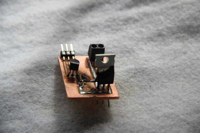
Chapter: Electronics production
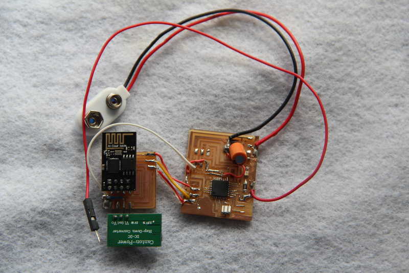
I started off by having the controller + esp in one board and the AC load switching as another board.
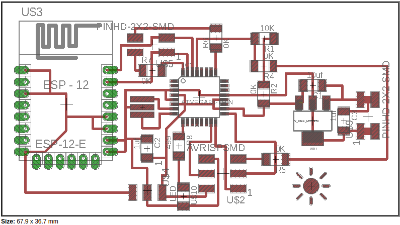
Controller + ESP8266
Even though I tried out with ESP8266-01 i designed for model 12E. the board comprises of
- Atmega 328P
- ESP8266-12E
- Control lines to AC switching circuit.
- some pinouts for debugging
- the 3.3v buck
- Vreg for converting 9V from battery to 5V for Controller and Buck
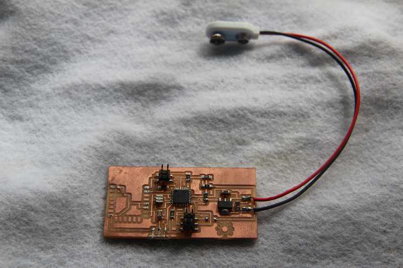
After soldering on the components and i was not able to get proper output. While trying to desolder the ESP8266 it got damaged and I had to keep aside this board. Instead i decided to have the controller, esp and the AC switching circuit separately.
Controller alone
It has just the 328p and output lines to ESP board and control lines to AC switching circuit.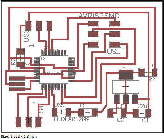
I plan to remove the ISP programming header after its use.
ESP8266 alone
After i damaged the first ESP 12E ESP 01 is what is left. Do i designed a board to accomodate the buck and ESP.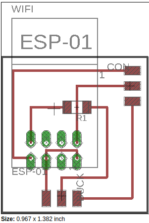
This will be connected to the controller board.
 .
.
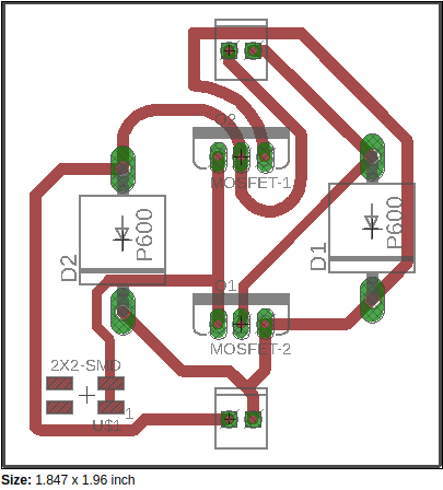
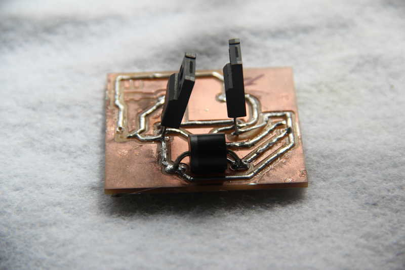
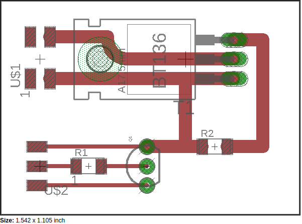
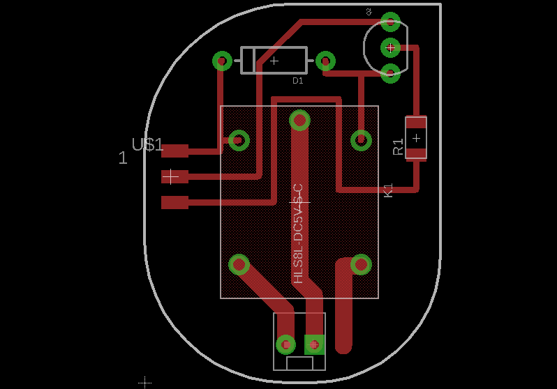
AC switching
The design of this itself took great time than anticipated. First i thought about using MOSFET for controlling the AC which failed miserably, then i tried TRIAC which also failed. The failure of MOSFET I believe is because i had P-MOSFET and I designed for N-MOSFET. While with triac I believe it is due to the lack of load between input and output connections. Finally I decided to have the mechanical relay for switching the circuit. The design process of the same and details are in week 13 . The MOSFET and TRIAC boards where actually blown up causing the CB’s to trip !! :D
Chapter: Programming
After getting the board ready for programming, modify the written code for the new controller upload it. Here is the final arduino code of the controller1
2
3
4
5
6
7
8
9
10
11
12
13
14
15
16
17
18
19
20
21
22
23
24
25
26
27
28
29
30
31
32
33
34
35
36
37
38
39
40
41
42
43
44
45
46
47
48
49
50
51
52
53
54
55#include <WiFiEsp.h>
#include <WiFiEspUdp.h>
char ssid[] = "abcd"; // your network SSID (name)
char pass[] = "*****"; // your network password
int status = WL_IDLE_STATUS; // the Wifi radio's statu
unsigned int localPort = 5000; // local port to listen on
char packetBuffer[255]; // buffer to hold incoming packet
char ReplyBuffer[] = "yuppee"; // a string to send back
WiFiEspUDP Udp;
void setup() {
Serial.begin(9600);
WiFi.init(&Serial);
while ( status != WL_CONNECTED) {
Serial.write("AT+CWMODE=1");
delay(500);
status = WiFi.begin(ssid, pass);
}
Udp.begin(localPort);
pinMode (7, OUTPUT); //relay
pinMode (8, OUTPUT); //LED
}
void loop() {
// if there's data available, read a packet
int packetSize = Udp.parsePacket();
if (packetSize) {
// read the packet into packetBufffer
int len = Udp.read(packetBuffer, 255);
if (len > 0) {
packetBuffer[len] = 0;
}
if (strcmp (packetBuffer, "ON") == 0){
digitalWrite(7, HIGH); //to relay
digitalWrite(8, HIGH); //to LED
}
else if (strcmp (packetBuffer, "OFF") == 0){
digitalWrite(7, LOW); //to relay
digitalWrite(8, LOW); //to LED
}
// send a reply, to the IP address and port that sent us the packet we received
Udp.beginPacket(Udp.remoteIP(), Udp.remotePort());
Udp.write(ReplyBuffer);
Udp.endPacket();
}
}

Chapter: Switch design
I am almost exhausted of time before final presentation. I hastily designed an enclosure which was laser cut and press fitted. It has a lid which can be opened. Also design the adapter which holds the leads for plugging into the plug point.
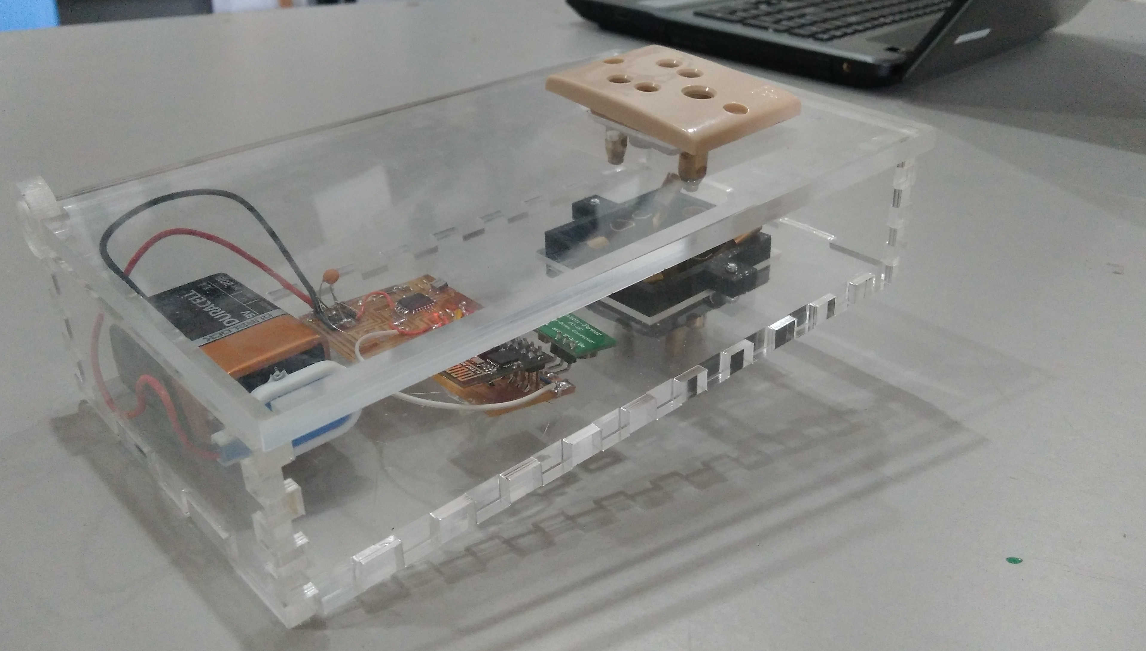
The work in pipe line
Since the presentation, I have been working on a new socket design. It is a work in progress and not yet finished. I hope to complete it in the near future so as to have a visually appealing compact design.
Learning outcome
The two week I spend on the project taught me many valuable leas sons, not just technical but managerial too. Had to manage the time and resources so as to finish the project. The only board I did before these weeks is the relay board which I made for output device week. Everything else had been made in the last and present week. The time calculated by me for interfacing ESP and making the AC switch was very inaccurate. Debugging took up most of my time. This further resulted in the shortcomings of the physical design of the socket. For planning the Academy i have been using Trello which is a great tool for keeping track of your activities. I am a person who procastinates very much but it helped me to reach here.
License
The MIT License (MIT)
Copyright (c) 2016 Vishnu Easwaran E
Permission is hereby granted, free of charge, to any person obtaining a copy of this software and associated documentation files (the “Software”), to deal in the Software without restriction, including without limitation the rights to use, copy, modify, merge, publish, distribute, sublicense, and/or sell copies of the Software, and to permit persons to whom the Software is furnished to do so, subject to the following conditions:
The above copyright notice and this permission notice shall be included in all copies or substantial portions of the Software.
THE SOFTWARE IS PROVIDED “AS IS”, WITHOUT WARRANTY OF ANY KIND, EXPRESS OR IMPLIED, INCLUDING BUT NOT LIMITED TO THE WARRANTIES OF MERCHANTABILITY, FITNESS FOR A PARTICULAR PURPOSE AND NONINFRINGEMENT. IN NO EVENT SHALL THE AUTHORS OR COPYRIGHT HOLDERS BE LIABLE FOR ANY CLAIM, DAMAGES OR OTHER LIABILITY, WHETHER IN AN ACTION OF CONTRACT, TORT OR OTHERWISE, ARISING FROM, OUT OF OR IN CONNECTION WITH THE SOFTWARE OR THE USE OR OTHER DEALINGS IN THE SOFTWARE.