Electronic Design
This week is dedicated for learning primarily electronic designing and electronic components and usage. As i have a background of learning and working with electronics, I am used to the subject. Neil explained briefly about the Passive and active components. You can get a good idea about the basic electronic components here.
I have experience in designing PCB’s using Eagle. But as Neil said, we have to try out different design softwares to have a better understanding. So i went through the following ones
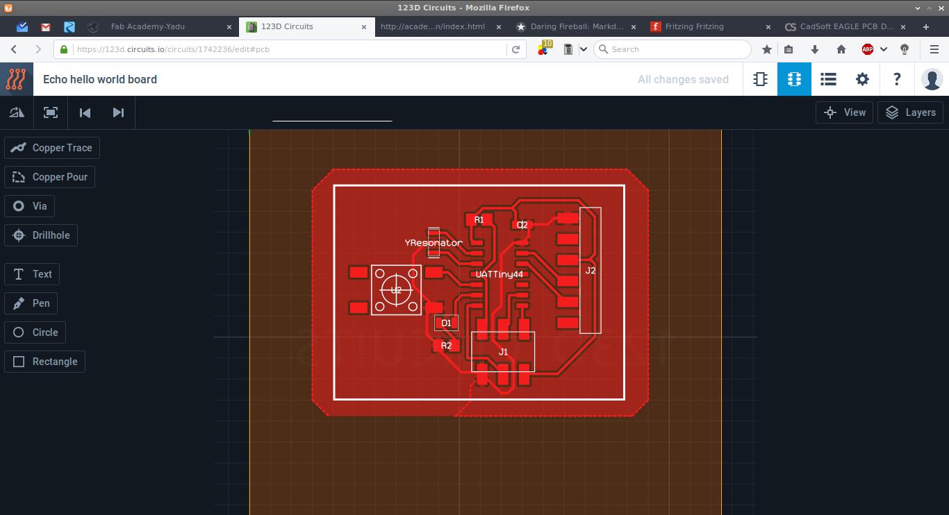
1.123D Circuits - which is pretty straight forward and is for beginners. This follows the standard design steps of drawing the schematics and then routing the board. Their component library is ‘OK’ and should improve. The search option is not helpful if we don’t know what exactly we are looking for.

2.Kokopelli - I started using Kokopelli to design circuits. For understanding easily Franc told to download and look into the .cad file of “hello ftdi” , which I got from the Fab Academy archives. Instead of starting from scratch, we can use the library set made my Neil, we just have to create the board alone. The programming is done in Python and is quite easy to understand and self explanatory. Franc walked us through all the steps from defining the size of the board, trace width, adding components etc till we export as .png files for milling.
After all that I decide to modify a board and make our own version so that we can get hands on experience on designing a board. I choose to modify the “Hello FTDI” board and add an LED and a switch. We opened the .cad file in kokopelli and added three components, a resistor,LED and a switch, using the libraries made by Neil. Franc taught us how to find the needed components from the libraries formed and how to place them on the board relating to the position of other components. This step is very similar to that in Antimony were we form shapes with respect to some basic figure. After the necessary changes were made we exported the traces and exterior files for milling. We milled them, soldered the components and formed the board. 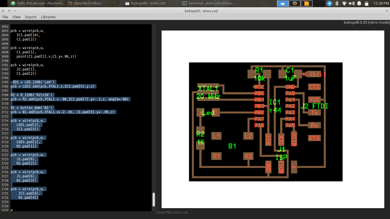 The designed board - Design Files
The code which i have added is as below. In the included files you can find it from line 3705 to 3733
1
2
3
4
5
6
7
8
9
10
11
12
13
14
15
16
17
18
19
20
21
22
23
24
25
26
27
28
LED1 = LED_1206('Led')
pcb = LED1.add(pcb,XTAL1.x,IC1.pad[5].y,z)
R2 = R_1206('R2\n1K')
pcb = R2.add(pcb,XTAL1.x-.06,IC1.pad[7].y+-.1,z, angle=-90)
B1 = button_6mm('B1')
pcb = B1.add(pcb,XTAL1.x+.2-.01, J1.pad[5].y+-.05,z)
pcb = wire(pcb,w,
LED1.pad[2],
IC1.pad[5])
pcb = wire(pcb,w,
LED1.pad[1],
R2.pad[1])
pcb = wire(pcb,w,
J1.pad[6],
R2.pad[2])
pcb = wire(pcb,w,
J1.pad[6],
B1.pad[3])
pcb = wire(pcb,w,
IC1.pad[6],
B1.pad[4])
5.Eagle - Eagle is a design software which is firstly very good and secondly a freeware. They give option to use it as a freeware as well as a paid premium version. The difference is that in the free version we can only design up-to 2 layer PCB’s while the paid one you have more layers. The software is also available for multiple platforms.
The workflow is as schematic –> Board. Essentially a design will have a file which holds the data of the schematic(.sch extension) and a file which has the board(.brd extension) layout. 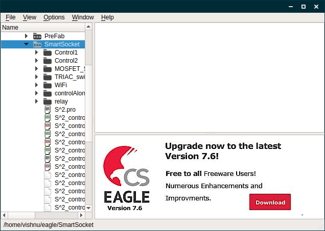
- Schematic - first we have to open a new schematic and add all the components needed for the board. Eagle accepts a command instead of clicking on the required tools, which i think is fantastic. The commands you need to know for starting are
add: This will open up the library window from which you can select the required component. There is a search option which is terrible, I consider it as the worst thing in eagle. most of the time it don’t return any result and is case sensitive. The workaround is to use wild cards before and after your keyword.move: this command helps you move around the parts you have added in the schematic.net: this is the command for making connections between components. It is analogous to making wire connections between components.delete: it is used for deleting components or net connections.copy: it is used for making copy of existing components.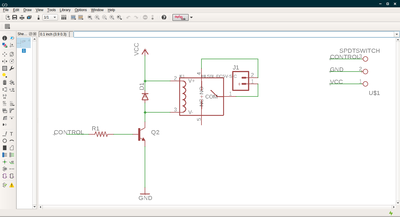
- Board - when you open this for the first time you will see a white box and the foot prints of the components you added in the schematic lying outside it. The first step is to pick them all and place it inside the box, which is the area where you can design the connections. Place all the components according to your wish and sense. After this you have to route, which makes the actual traces in the final PCB, according to the connections you made in the schematic. Their are two options for doing it, route automatically using
Autoroutetool or manually route using theroutetool.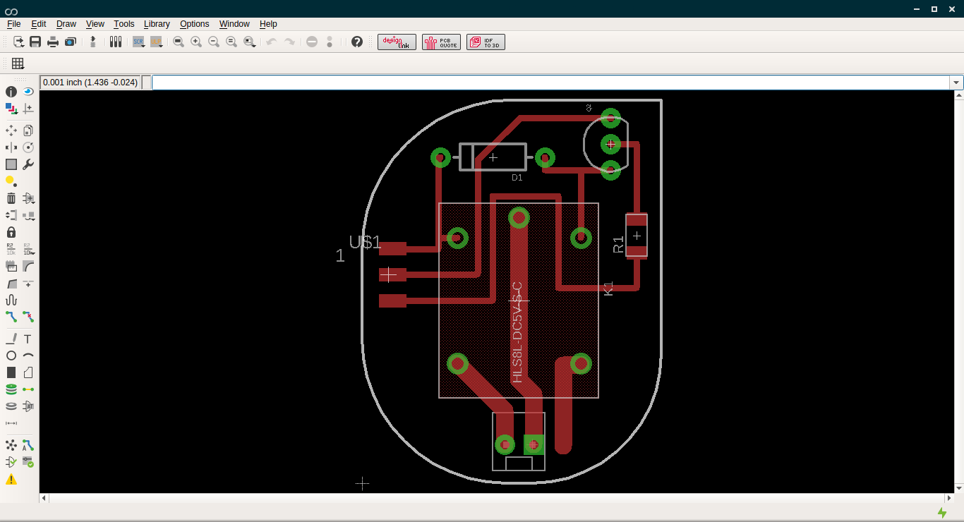
Eagle design files
Fabrication of the Echo hello world.
The circuit designed in kokopelli was used to fabricate. I used the Fabmodules along with modella to mill it and later on soldered the components. You can refer the week-4 for knowing how to mill the board and solder.

