Week Six: Electronic Design
What we are going to do this week is to design our own PCB board through using the Roland milling machine. The whole process can be broken down into two parts. One is to design the board, including the traces, interior and exterior lines. Another is to actually solder all my parts onto the board. I use Kokopelli to design my PCB board, which is in my great convenience. The design by code is clear and systematic. One can find the software on the website "http://kokompe.cba.mit.edu/". We complete the installation through typing the following three commands in Terminal
-make clean
-make fab
sudo make install # recommended and needed for kokopelli retro
Kokopelli has many lines. In order to fully access its utility, one has to understand what does each line represent. There are several lines that are particularly important:
LINE 18 - 24:For exporting, uncoment the line depending on what output image you want. to render out.
LINE 3555 -3590: Graphics
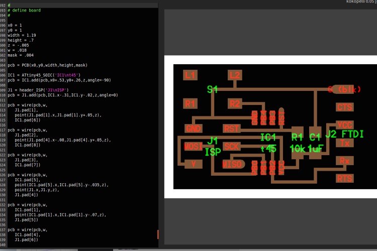
LINE 3593 - 3690: Define Board
LINE 3697 - 3714: Code for defining exporting options.
LINE 3716 - 3726: Set limits and parameters.
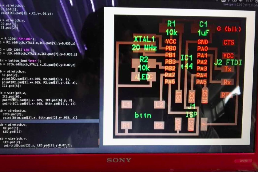
After Using the command "kokopelli -r" in the terminal to open the software. I start to design and modify my design. I took away the "#" from the "output = 'traces, labels, and exterior'" in order to see the full board. Then I added all the components I need, including Crystal, Resistor, Attiny44, Button and other plugs. Then I added wires I need. The definition of each component follows a similer pattern as shown in the picture. The wire isdefined in the following fashion: pcb = wire(pcb,w, point1, point2, point3...)
-
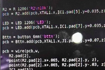
Step1: How to define a component in Kokopelli
-
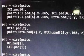
Step 2: How to define a wire
-
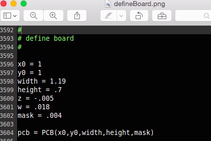
Step 3: How to define a board
-
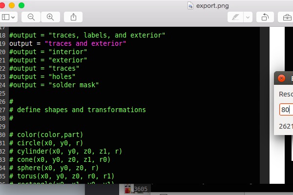
Step 4: Export
-
Step 5: The interface of Kokopelli
-
Step 6: Another angle of Kokopelli Retro
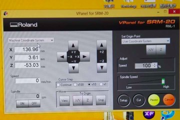
The next part is to create my actual board through the milling machine. This is similar to the process I did in the past. All the parameters and procedures I need can be found in the materials documented from the last week. The milling process is divided into the milling of exterior part and traces, which are also old stuff.
-
Step 7: Repetition of old procedures from last week
-
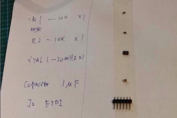
Step 8: Collection of Components needed
-
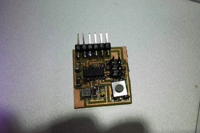
Step 9: Final Outcome