SoundFlower
The Academy is almost finished and I've been thinking about the new project all academy long. So it's time to choose one oof the ideas and go for it, starting now! (I know I'm already late). I'm going to list different ideas I've got for projects and then choose one.
The original idea is a vest with electronics for cyclists. That would involve some laser cutting the vest. Design the straps maybe with some 3D printed clips. And design the electronics, involving an IMU and a switch system to indicate turn direction.
From week 7: make something big, I thought I could expand that part of the project to continue designing around the arcade machine. I could design a board to act as a joystick taking the inputs from the end switches. But still counting on an RPi for the emulator processor. I can also design a button and probably a joystick. Another idea was to have it accept some kind of "virtual" coins or tokens like you can go to a Fab Lab and when you're able to design a fabricate those tokens you will be able to play some video games.
I've been teaching Scratch among other tools to get kids into programming for the last 3 years. And I've been using from time to time, extensions and derivatives to use Arduino with Scratch. Well I always started the courses without the computer, by making algorithm games that involved concepts of programming but not involving computers. I'm thinking about making a physical interface for Scratch, what I visualize now would be like big wood blocks with tiny processors communicating to a master processor that communicates with the PC. I think that is important to feel that writing code is done with a computer because is a convenient tool, but the problem can be solved with a physical interface. I think this may be the most interesting project and I'll pursue it, but I think it's too much for just this month.
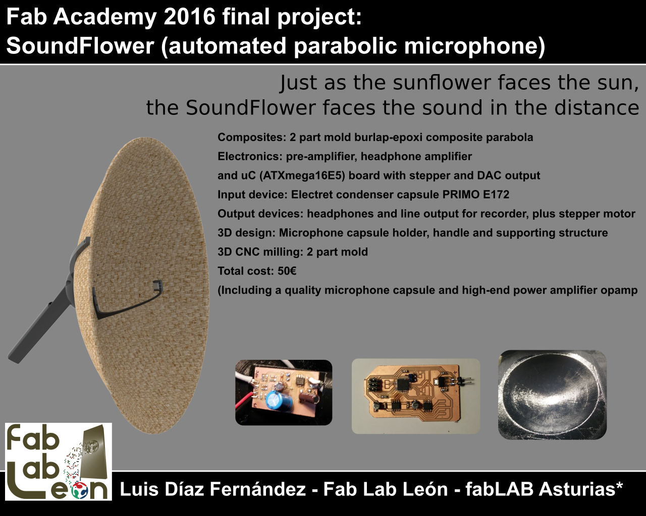
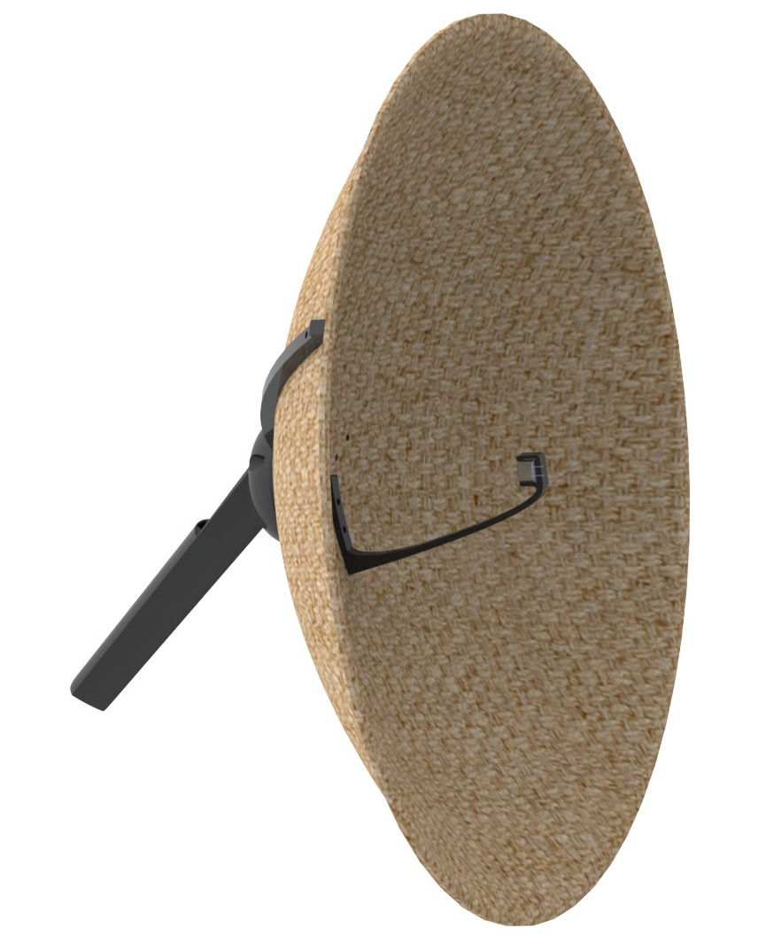
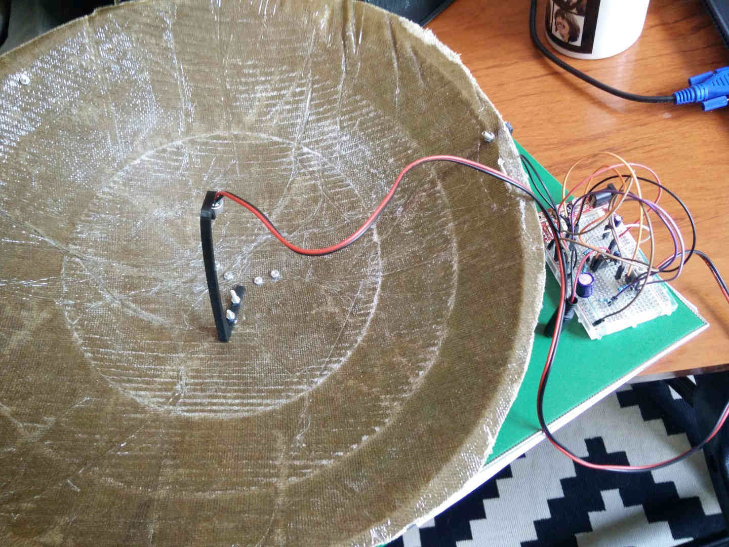
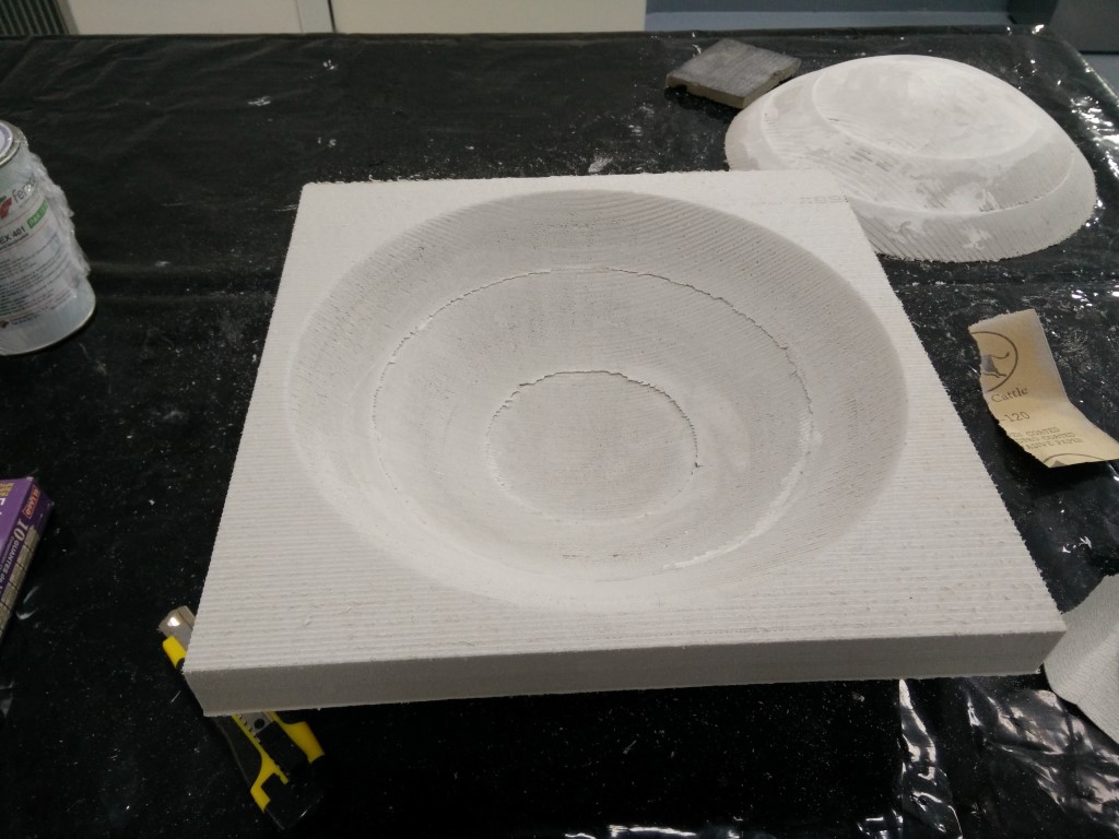
From week 14: composites, and after the first fail, I've also seen some final project potential on the parabolic surface I've made. I could maybe try to design some parts for holding a microphone at the focus of the parabola and have a "spy microphone". I will also design the electronics for the mic preamplifier, maybe have a controlled output depending on the threshold of sound recorded. And Nuria pointed out the possibility to add a motor base to have it moving. At first, I was thinking about taking it out on hikes and try to listen to animals, but with a motor, you can make it static and looking for audio sources, the louder the better, like an audio sunflower, a Soundflower. Obviously, you don't need a parabola to make a SoundFlower, but with a parabola makes it more directive and can perceive quieter sounds.
And the winner is... (soon)
The Soundflower! I picked this because it combines enough of the units covered during the Academy.
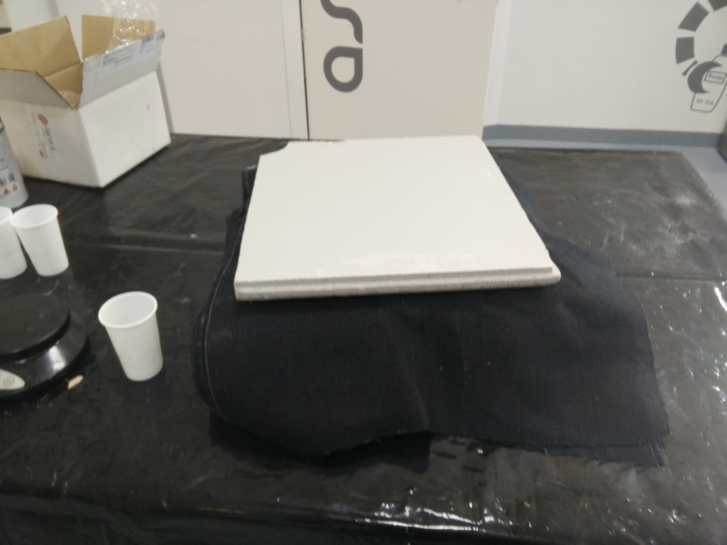
Composites: main parabolic reflector
3D modeling: Mold for reflector and other parts for 3D printing
3D CNC: parabolic mold for reflector
3D printing: structure to hold the reflector in place and attach it to the motor structure
Input devices: microphone
Output devices: stepper motor
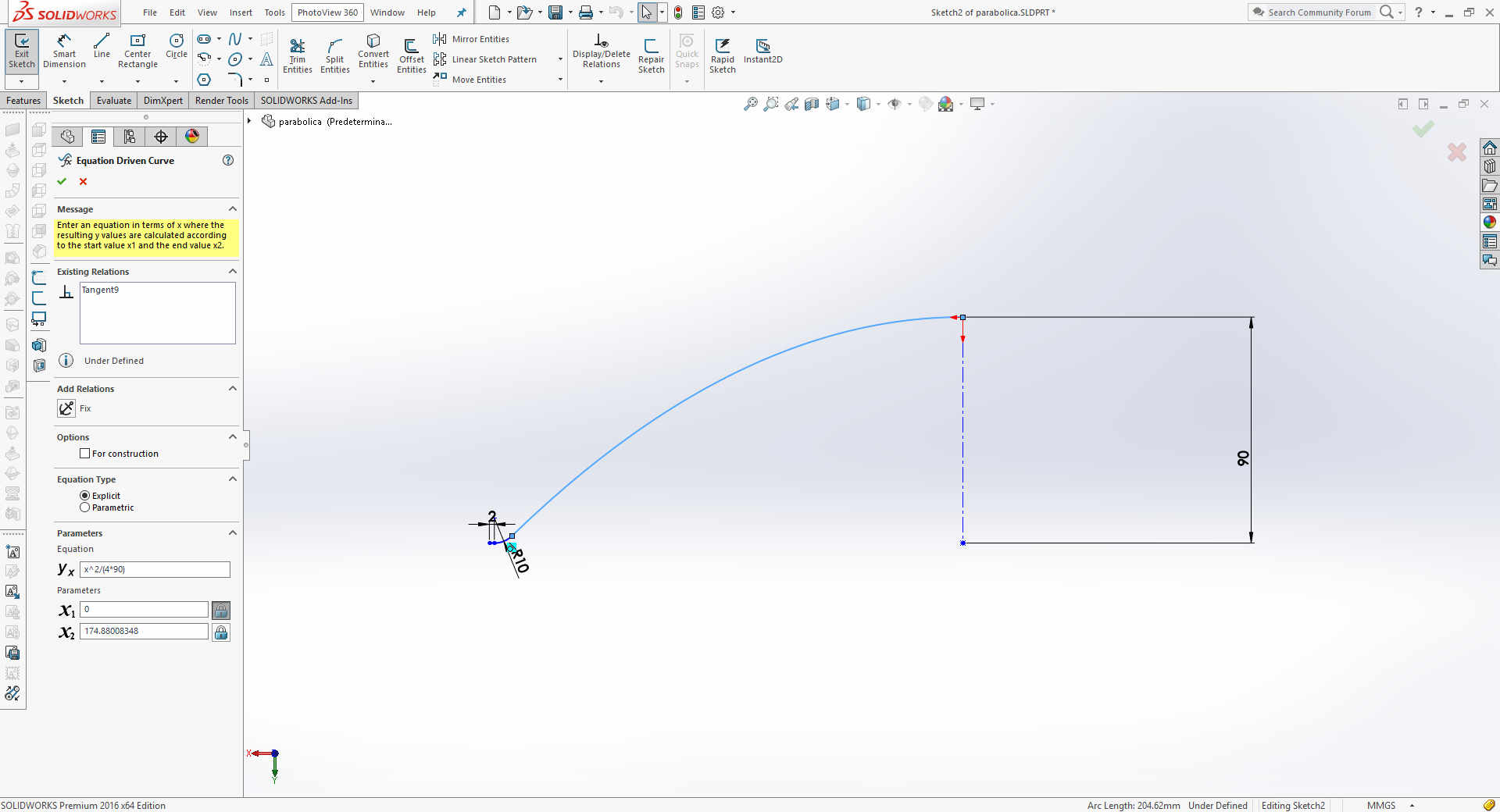
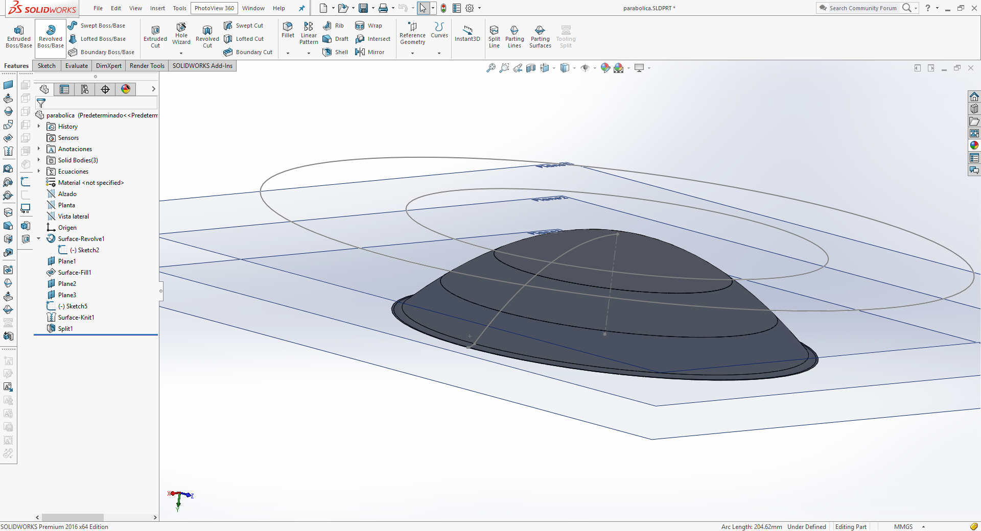
-Design a parabolic reflector (Done!)
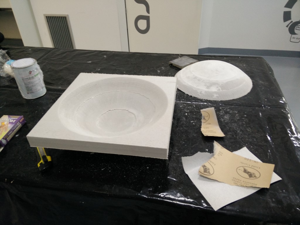
-Design a mold for compositex (Done!)
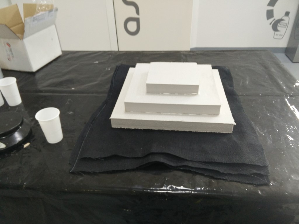
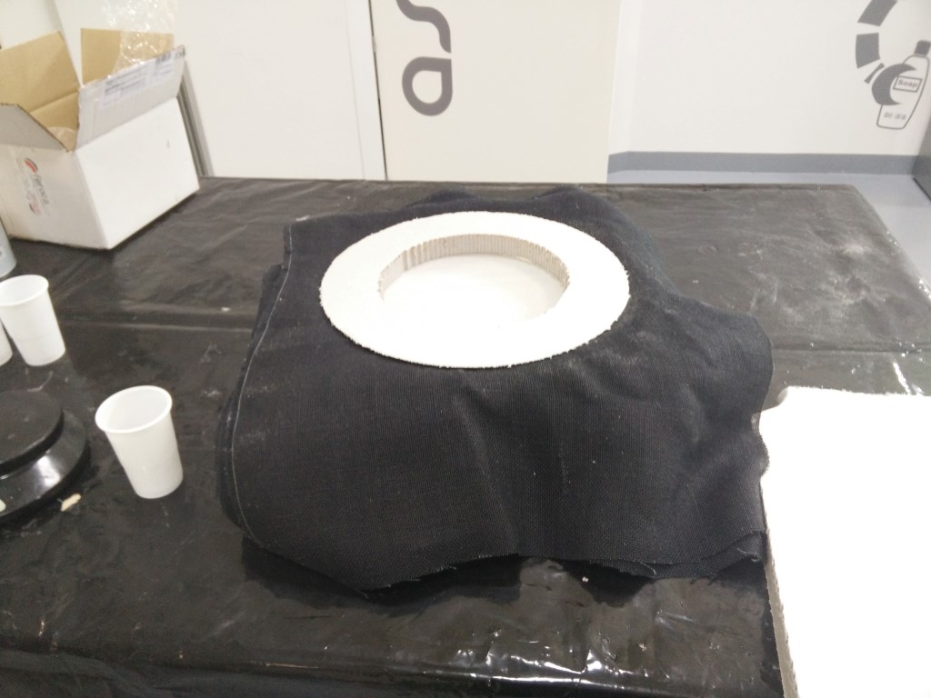
-Build a composite reflector (Done!)
-Design the electronics (Done!)
-Fabricate the PCBs (Done!)
-Assemble the PCBs (Done!)
-Design a structure to hold the parabola (Done!)
-Design a handle integrating at least the pre amplifier and a jack output (Done!)
Anyway what I really want to design now is an interface for HAB tracking. I'm participating in a hobbyist HAB group and we are launching our first HAB this June, probably a few days before the project presentation. You can check our progress at ashab.space but for now, it's only in Spanish. I thought of a device with GPS and magnetometer, that inputs coordinates (of the balloon) trough serial port, compares with your coordinates and heading and points through a 16 led circular array, the position vector direction relative to you own position. It would be great for car tracking! That's what comes next the academy and hopefully will be available for the second launch
UPDATE 06.06.16:
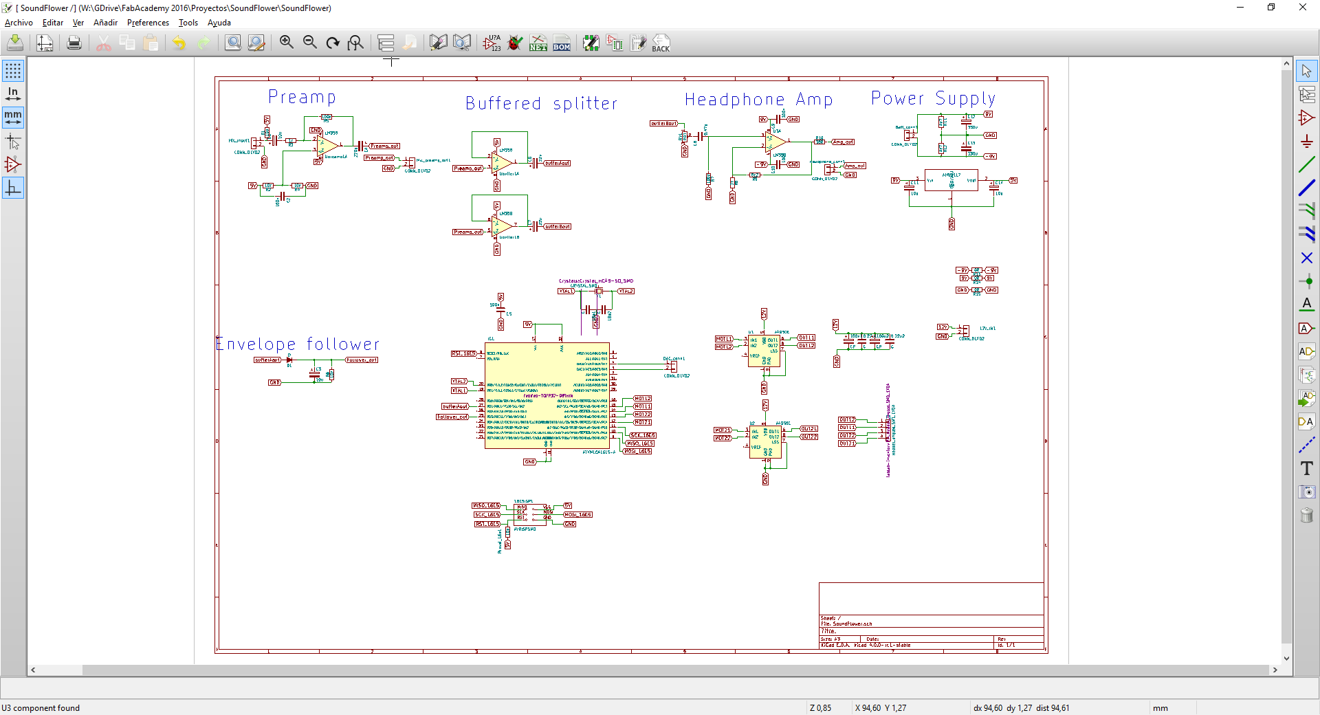
Two weeks left for the presentation and I'm with the electronics and initial testing. I'm designing a board with the following features
Microphone input
Microphone preamp
Voltage follower splitter
Envelope filter
Headphone amplifier
uC
Bipolar stepper driver
I started designing the electronics having multiple boards with different functions for the sake of modularity and quick debugging. So I'll have at least 3 boards, maybe 4. One to preamplify and output audio signals both for a headphone amplifier and to a microcontroller. The second one the headphone amplifier itself. And the third one the one with the microcontroller and the motor driver. I may split motor control and microcontroller, but I think is small enough to keep it together in the same board.
I started by protoboarding the circuit to test the microphone a little bit and see if the parabola it's working. After assembling a simple preamp with 0-5V supply using an LM358 opamp. I get some noises but most probably due to the components not having a good contact on the protoboard. I'll try to debug it a bit, but as the noise come and goes, when it goes away for a second I can hear clearly the microphone.
Update 07.06.16
Great day today, I've reassembled the preamp circuit on another protoboard and the sound is quite clearer now, it even works with headphones. I've finished the schematic including everything and made a board out of it. Now I'm thinking to have everything in the same board. But probably will trace independent board versions. I'm still unsure about the board power supply, I need 5V for the microcontroller, 12V for the motor and +-9V for the audio amplifier. Ideally, it would be great to have a single power supply but by now I would need two 9V batteries for the audio amplifier and microcontroller, and 12V for the motor.
Update 08.06.16
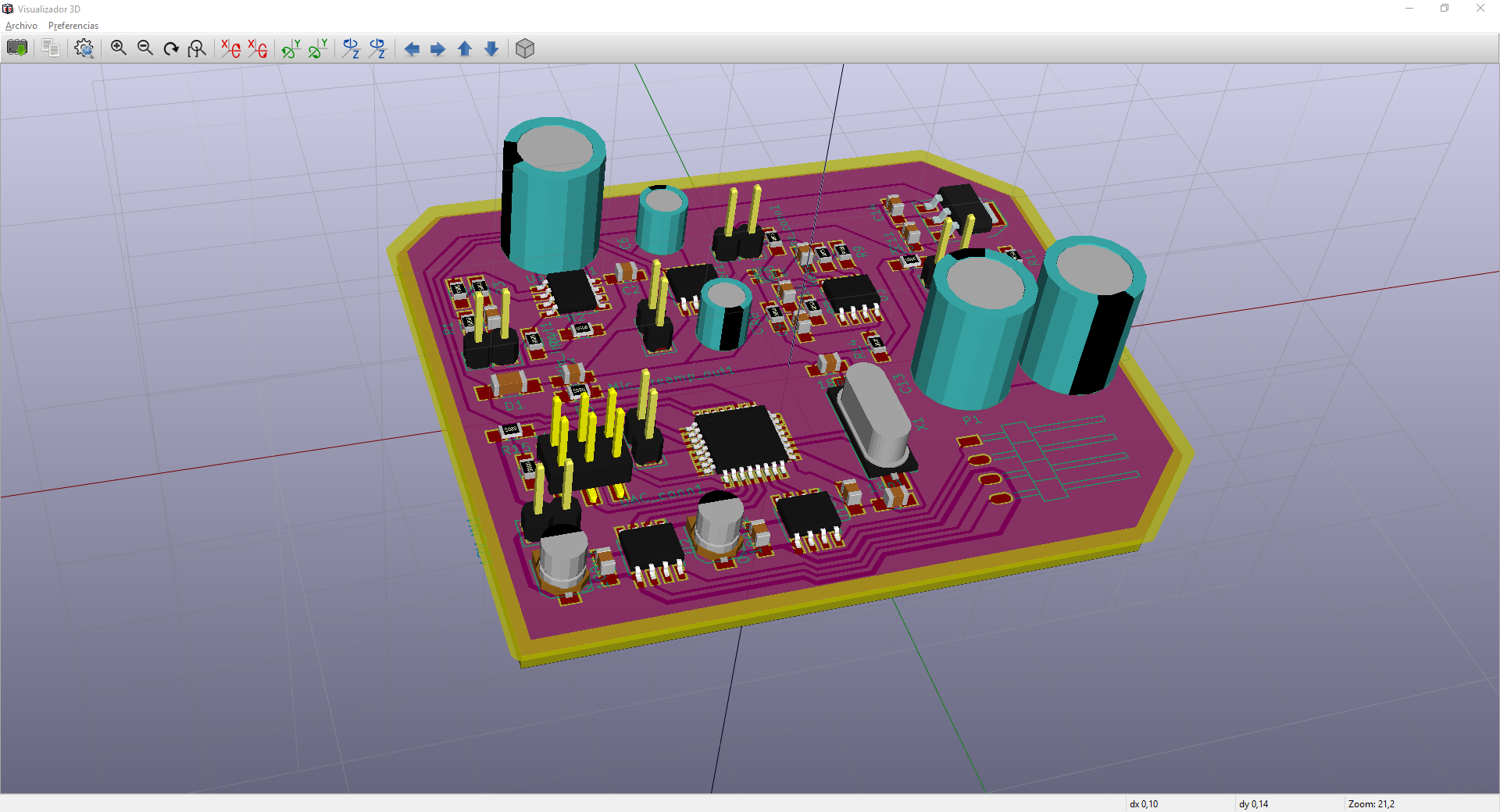
I'm going to start uploading some pictures of the design
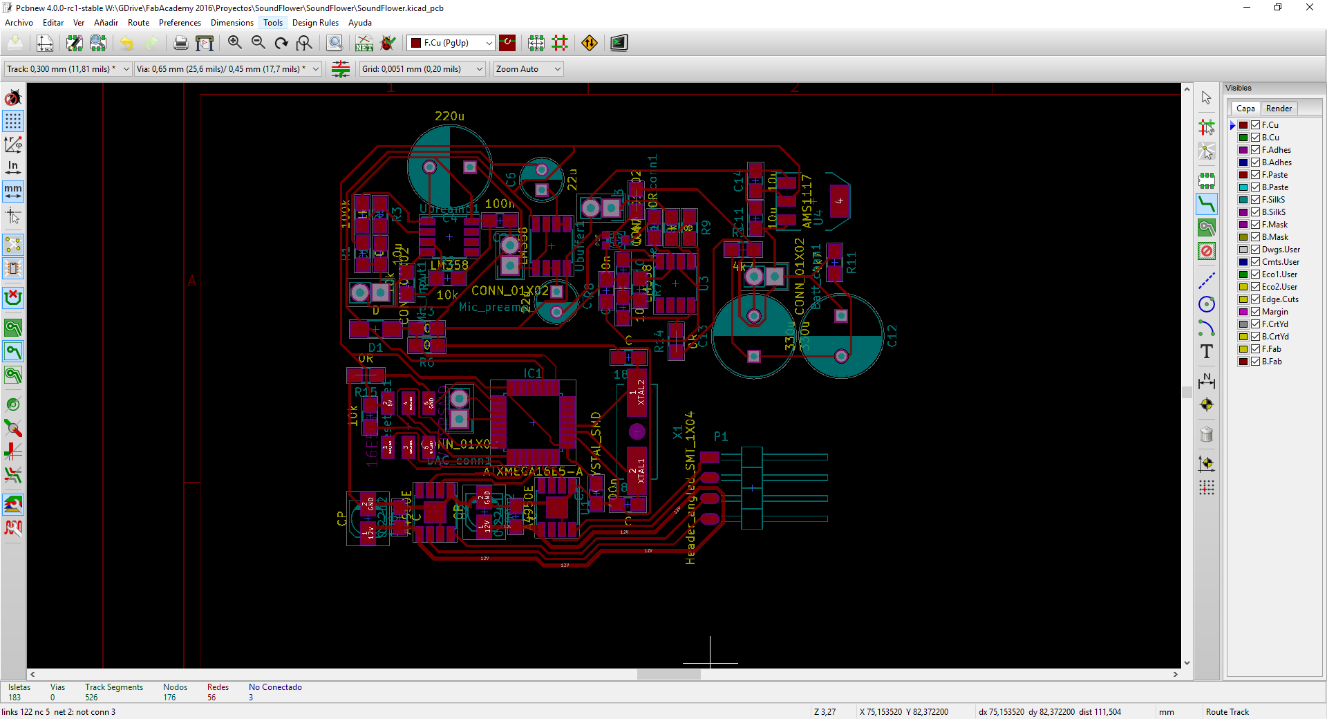
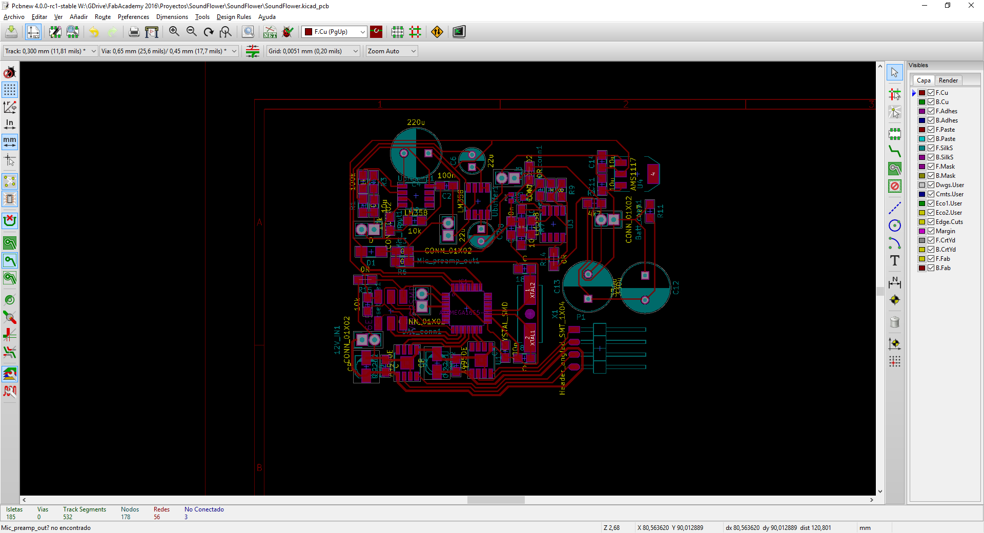
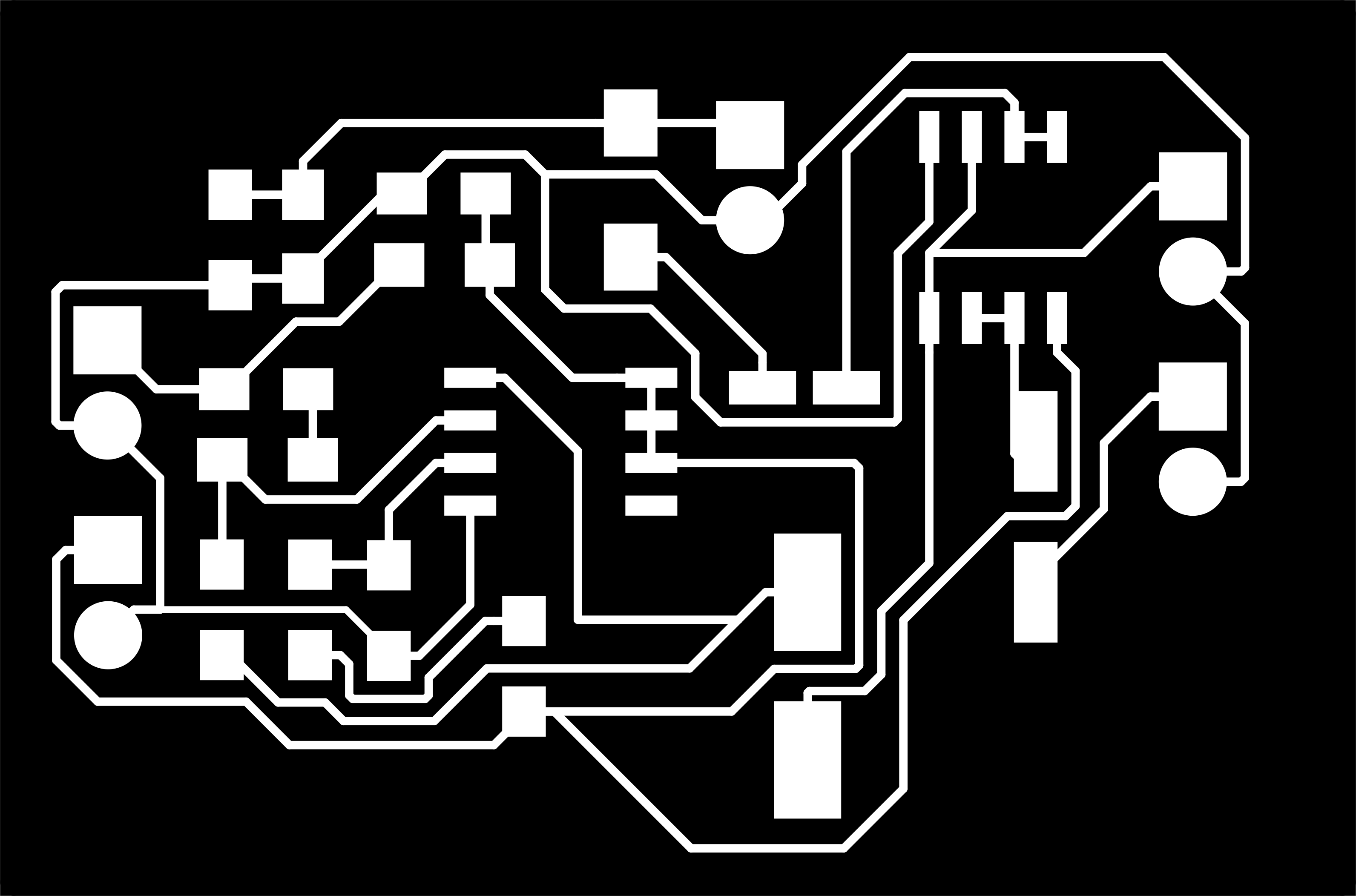
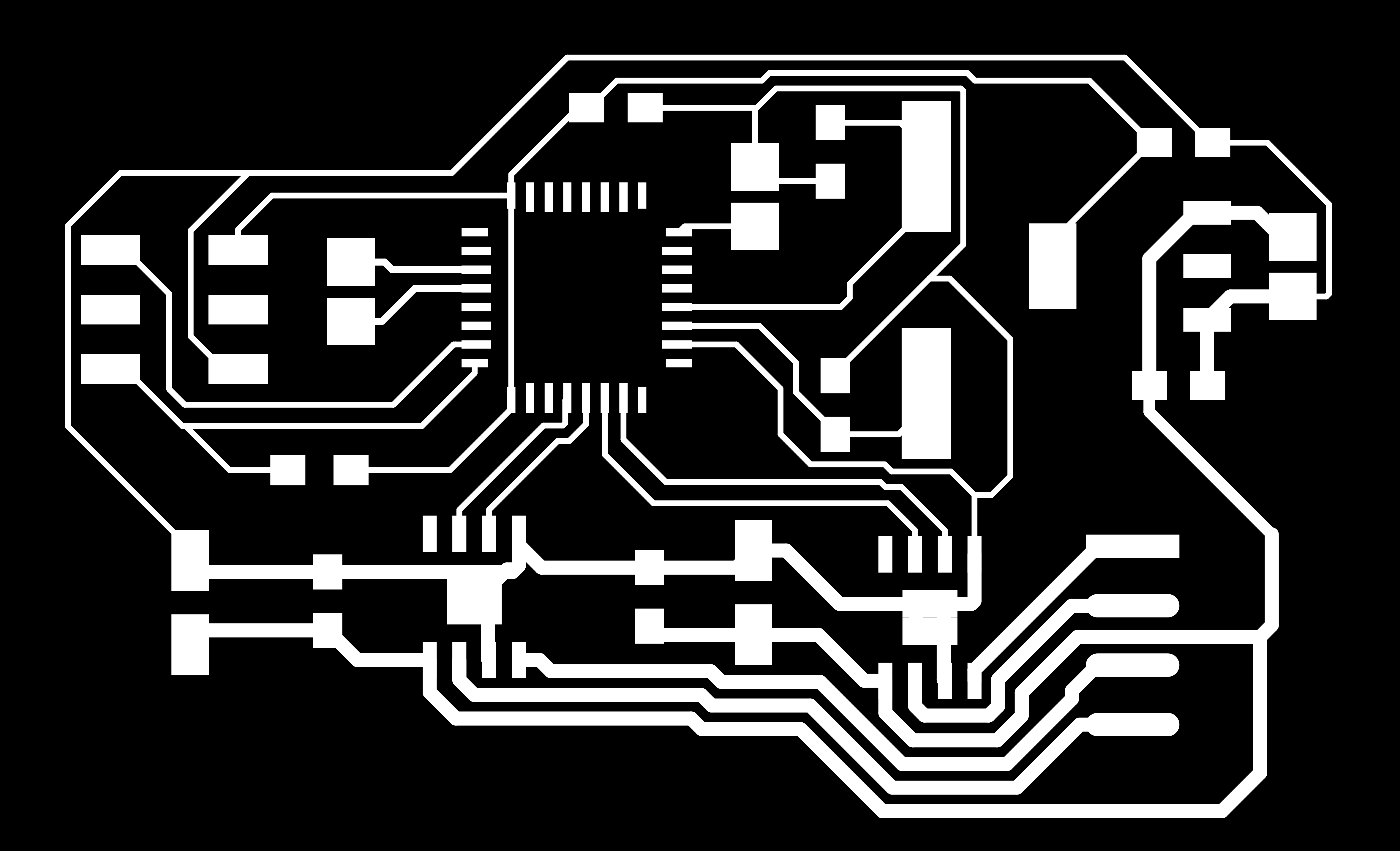
The first board design is the following one, I'll try to mill it tomorrow, but still need to do some work on it, check all the footprints and components available
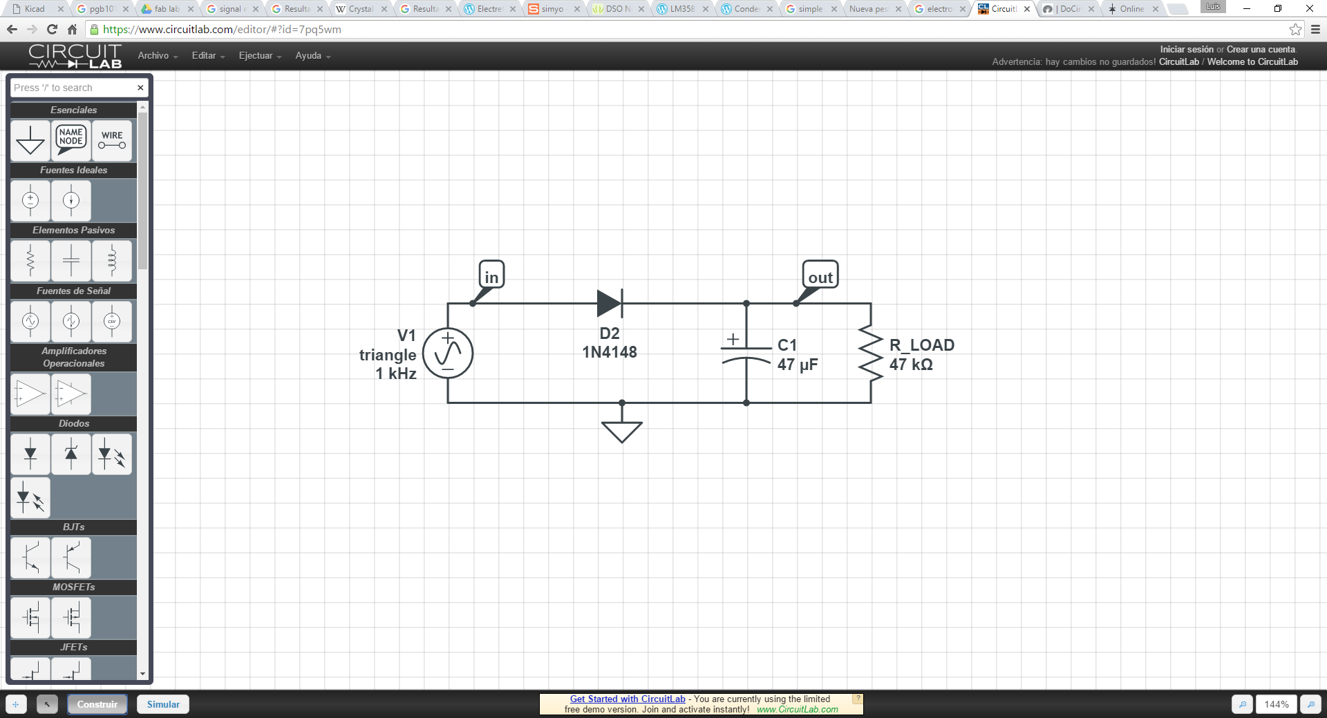
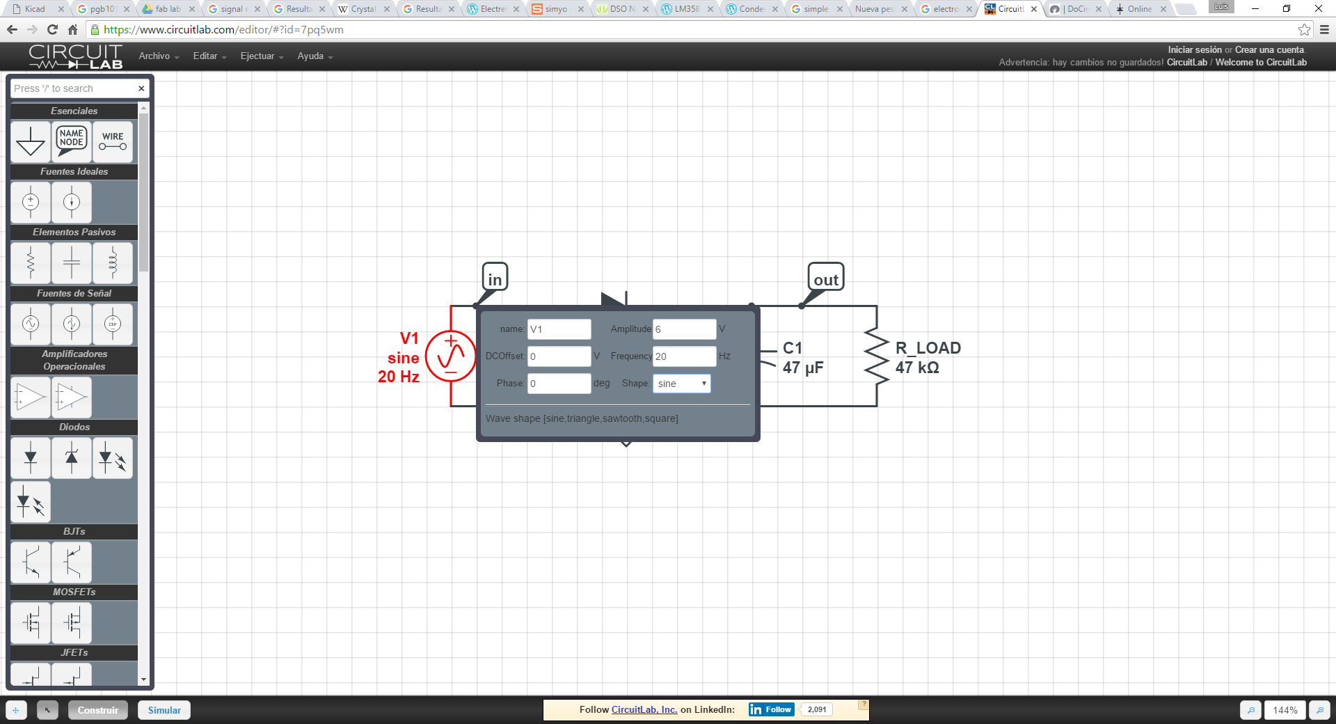
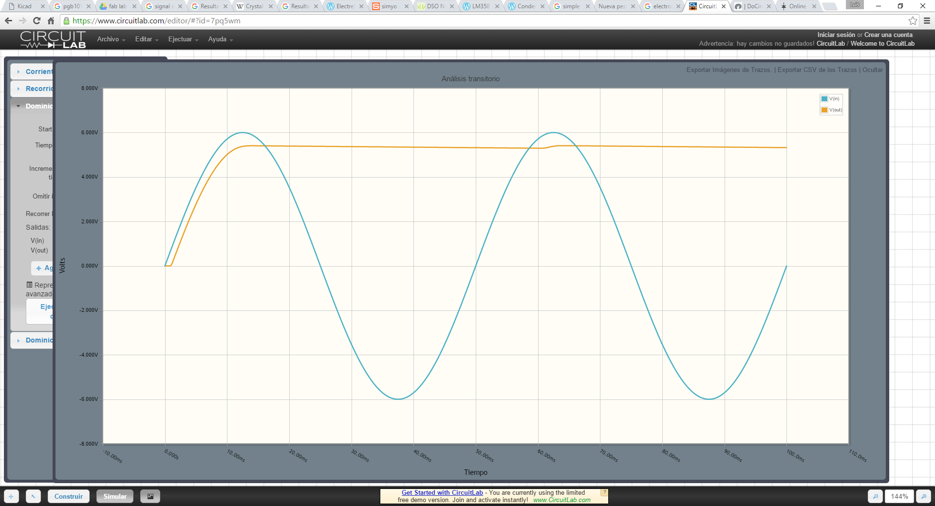
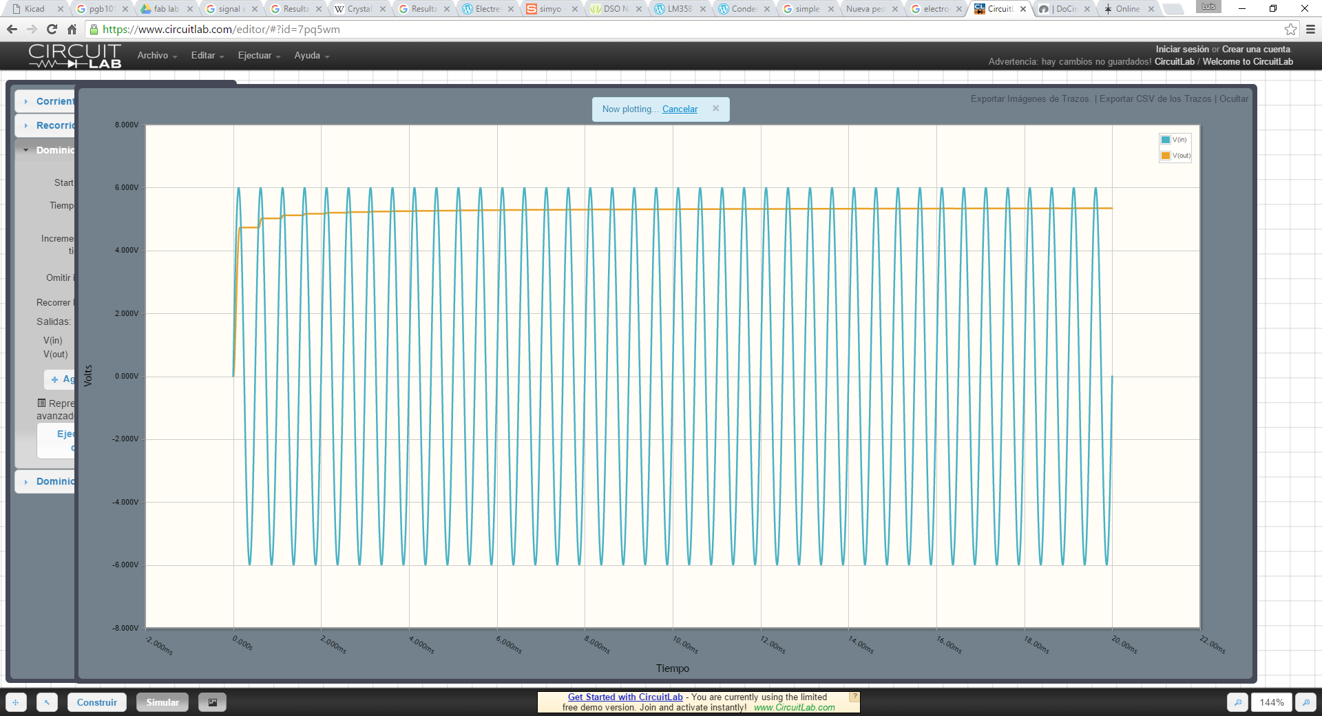
One of the parts of the circuit is an envelope filter to get a measure of the signal level, for that I've used a circuit simulator: www.circuitlab.com and simulated different input frecuencies to get a good combination of resistor and capacitor for the filter.
Update 9.6.16
Another day with KiCad and loving it more and more. Yesterday I had a version of the full board with every feature in it, but at night I realized that I've used an SMD footprint for the headphone amplifier and I just have a DIP OPA2132. So it was a good exercise to do a bit of footprint design. I started with a footprint for the DIP8 Socket and adapted the pads to be 5mm long and SMD type, starting from the center of the pad, not centered where the pad was. Moreover, I also started splitting the different features to different boards. I have to say that having it previously on a big schematic is pretty straightforward to do smaller schematics by importing a previous schematic and then deleting what wasn't needed, but it keeps all the footprint associations
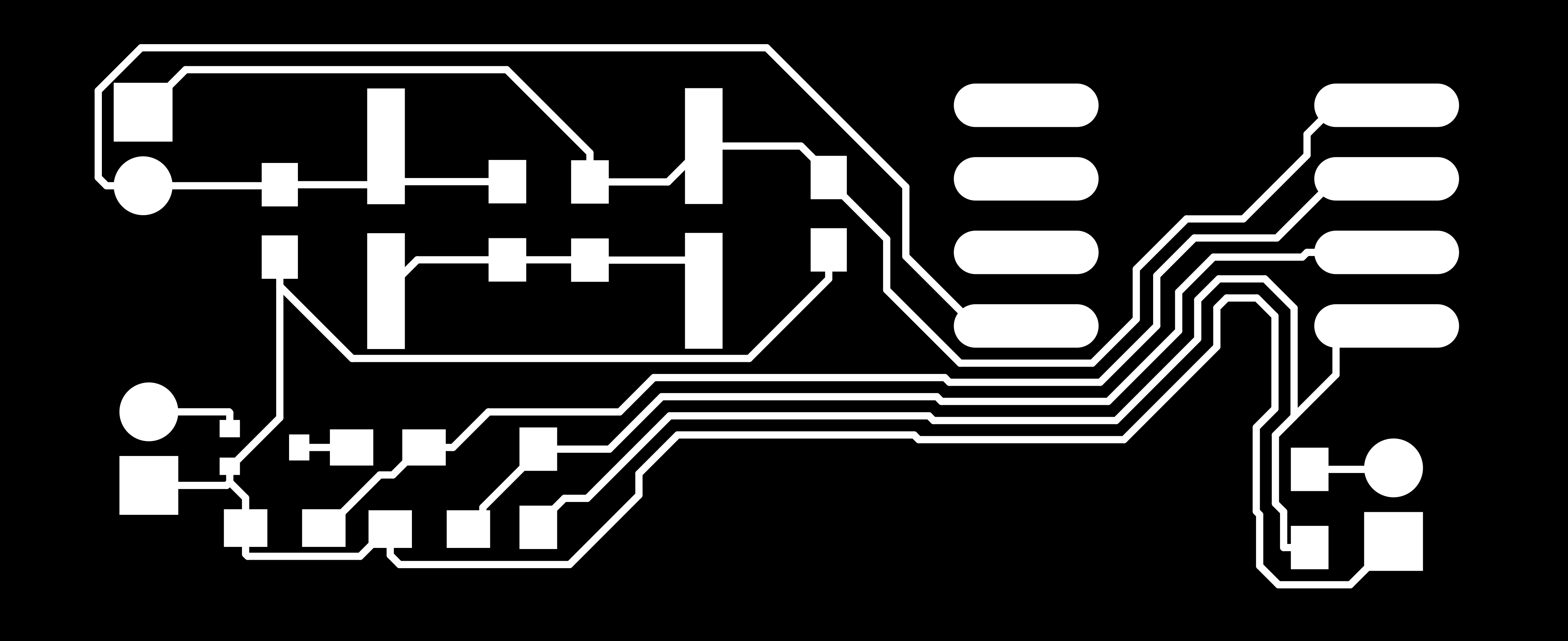
I've made three different boards, one with the microphone preamp, buffered splitter and voltage follower. Another board which is just the headphone amplifier. Another one with the microcontroller and the motor driver. And probably will make a power supply board. The preamp runs at 5V, the power amp at +9/-9V and the µC board with the drivers runs from a 12V source using a 3.3V AMS1117 voltage regulator for the microcontroller.
I still want to modify the board that includes everything because it doesn't have the SMD footprint for the power amp. The planning is being fulfilled more or less. And
Update 14.6.16
I'm back in León this week for four days working on the final tasks of the final project prior to the presentation on Monday. So first my planning for the next four days is:
-Tuesday: mill the 3 PCBs I'm using (preamp, power amp and µC unit) and start assembly of the boards
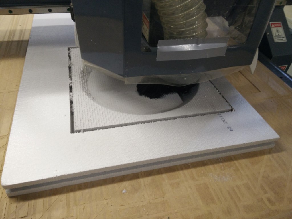
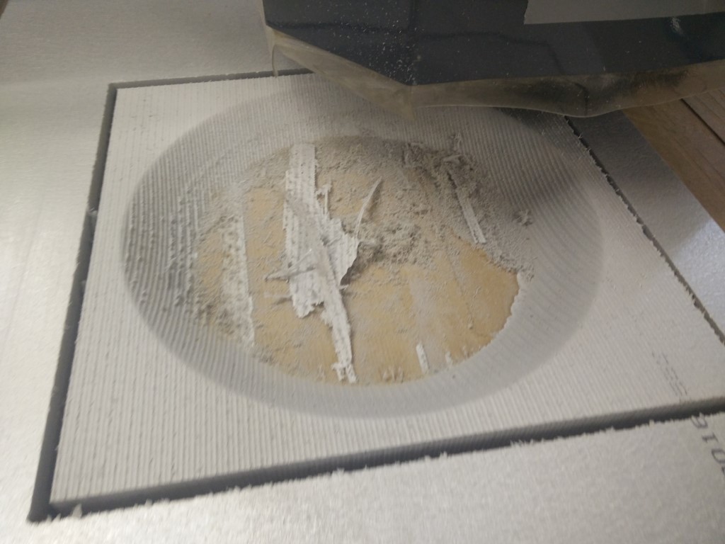
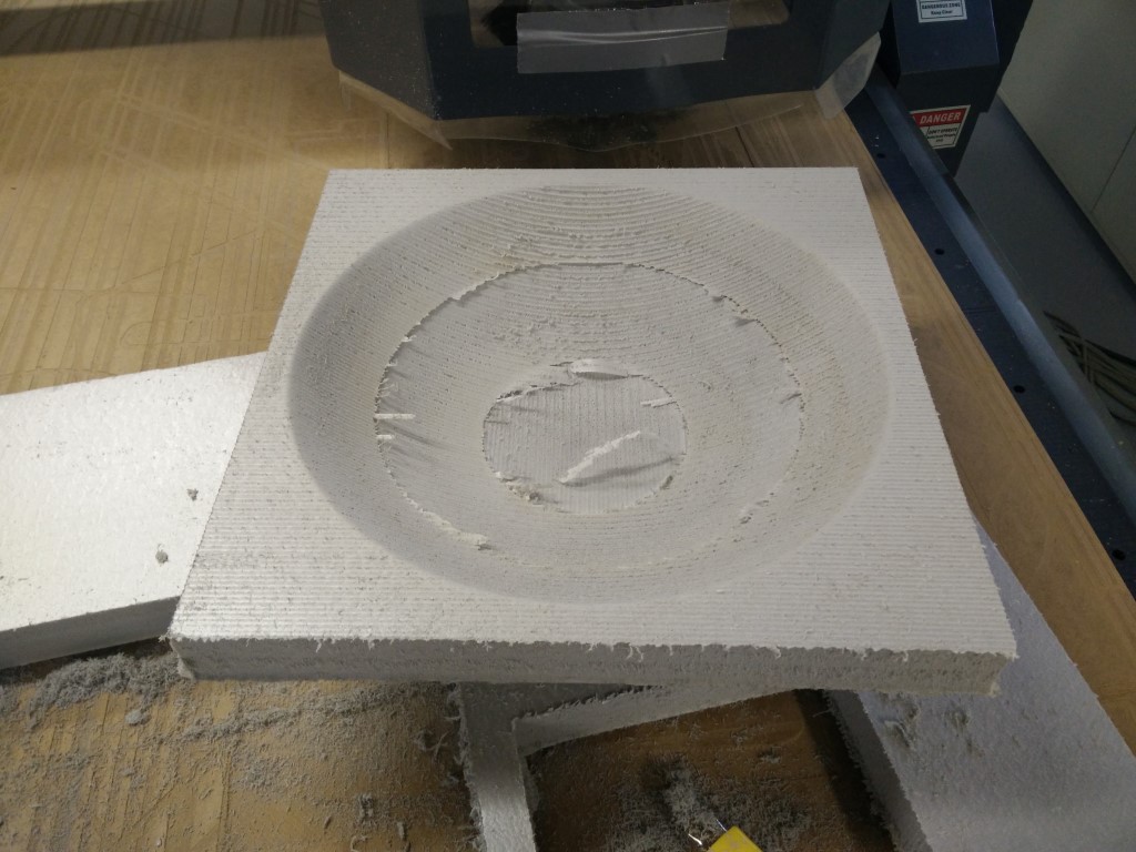
-Wednesday: As suggested by Neil, make another part of the parabola mold to have a 2 part composite mold
-Thursday: Finish the milling. Electronics testing and programming. Composite casting.
-Friday: Final assembly and testing and go back home to finish the video and the slide on the weekend.
I'm starting with the electronics because I'll probably need some debugging and the pre-amplifier is the minimum to have something functional for the presentation. On those three weeks between the presentation and the archive freezing, I still want to work on the µC control for a stepper to move the whole structure around looking for sounds. Because even though Neil suggested that a working directional microphone would be enough for the scope of the final project, we reviewed today the requisites for the final project and it should include an output device and some microcontroller programming. So even when this may not be fully tested, I want to reflect my intention to add this to the project that I'll keep updating in the future.
Today was pretty straightforward as the PCB manufacturing workflow is quite tested during the Academy. I'm still using 4€ mill bits for the PCB traces with great results, definitely great bang for the buck. I just ran into a problem today with fabmodules (offline) not calculating the path of a... transparent filling PNG file, of course, it wouldn't detect any borders to calculate the cutout.
Update 15.6.16
-Tested the preamp board, enough for headphones, a bit of distortion, better with 12V supply
-Buffered outputs not working, envelope filter not working
-Tested the power amp board,
-Tested both boards, very little gain
-different power supply 0 +12 on preamp -9 +9 on power amp
-Soldered the µC booard, lots of errors, bad header for xmega programming
-Prepared the files for milling the second part of the mold for 2 part composite mold
For tomorrow:
-redesign and make a proper µC board
-redesign preamp board
Update 16.6.16
This happens a lot to me, yesterday I was trying to debug an error in the new preamp board with the correct power supply to the LM358 I'm using for buffering the signal. It was late, I was a bit tired and none of the things I've tried seemed to work. So I called it a day and went back to the room but didn't push trough the night with the documentation. Just decided to rest a bit, read something and get early to bed. So today was a matter of 10 minutes to find the solder blob that was connecting the microphone signal to ground. I remember when I worked as a programmer having this same issue, a problem I couldn't solve in the last hours of a day being solved in the very first minutes of the next day. So the preamp works now, it still has some distortion, though.
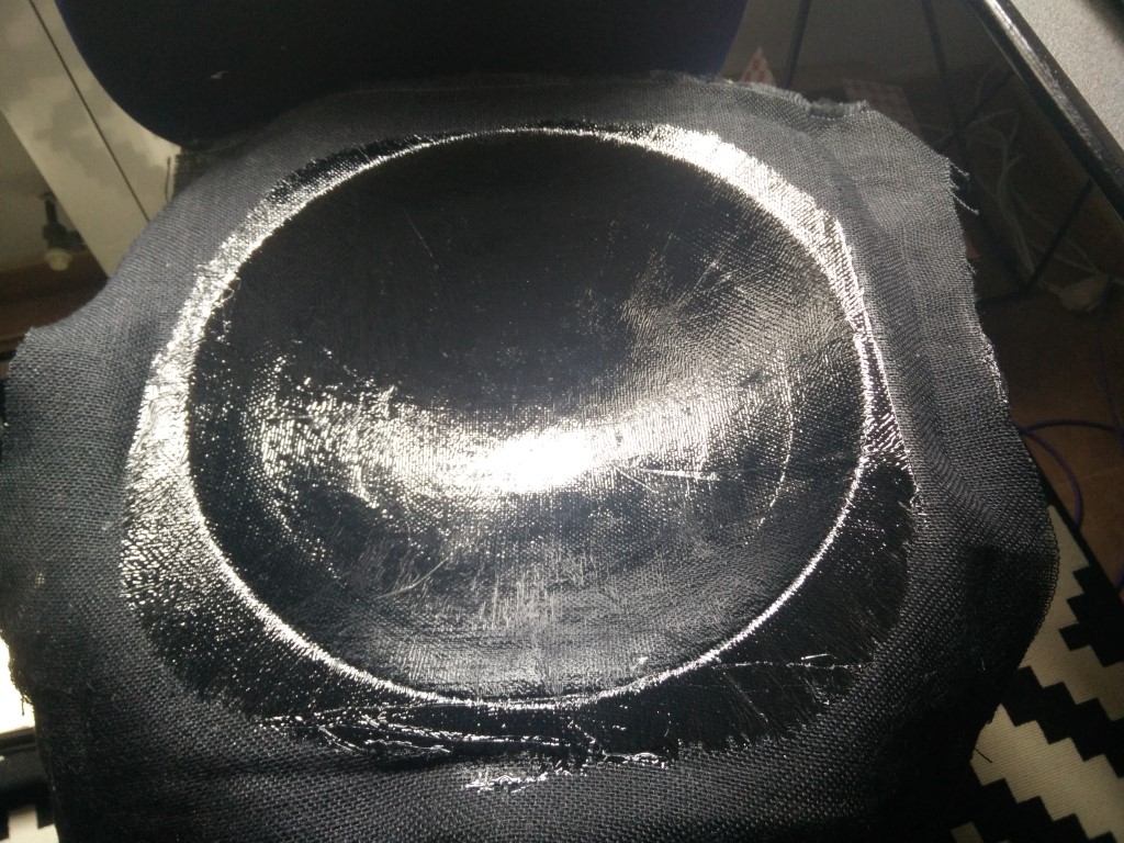
Hice el composite sin darts
Update 17.6.16
Today when I was driving back, I noticed that the vacuum was being lost, so I stopped and put the vacuum bag in the trunk with some weight on it, but it was just maybe 3-4 Kg from a soldering station. As soon as I got home, I placed the mold on the ground, re-applied vacuum and put about 25Kg of weight on it. Let's see how it goes when I get it out of the mold tomorrow.
Update 18.6.16
After coming back from León, it is time to finish the version for Monday's presentation. Still need to finish the design of the handle and print it, as well as modifying the mic capsule holder arm a little bit, adding a couple of holes to pass and fix the cable and a bit dimension modification for the grommet to fill better (it is a bit tight now).
Also time to get the parabola out of the mold. I'm a bit worried about the vacuum loss yesterday, fingers crossed...
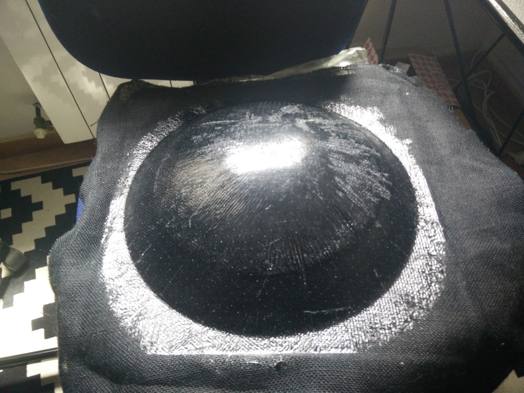
The result is promising, still a bit sticky so it will get stiffer. It is not super-stiff, but way better than the first version.
Electronics


Microcontroller
The SoundFlower is intended in the future to be able to autonomously face the loudest sound. Even when is a little bit out of the scope of the first prototype, that is more focused on getting a good parabolic reflector, it is advised for the final project to include some logic. What I need to do is to have a microcontroller board with some audio input and a motor output. That way I will be able to measure the sound while moving the Soundflower. So I started prototyping that part even when it's not going to be integrated with the microphone for evaluation.
In week 13 I've used an ATtiny44 for the output devices assignment using also a couple of A4953 for driving a bipolar stepper motor. But I wouldn't just want to repeat the assignment for the final project so I went and pick a slightly different microcontroller, it's still an AVR but from the Xmega family, a ATXmega16E5 that I've to choose first because I wanted to try it, but also because it has 12bit ADC and DAC, which is interesting when using audio. So for the scope of this prototype, I will read the input value from the microphone and get a value for the loudness for then compare different values from different positions. And the ability to drive the motor, independently of the sound level registered.
Another new thing in this final project programming is the use of Atmel Studio Atmel's IDE built on top of Microsoft Visual Studio. I'm using the latest version Atmel Studio 7 on Windows 10 using an avrispmkii programmer using PDI. I had some trouble getting the right drivers to work until I found Zadig a tool for installing USB drivers that includes the libusb 1.2.6.0 which worked nicely for the avrispmkii. Once the programmer was recognised I created a new project and started the main.c file with the code from the full stepper example from the archive. I started by following a good tutorial that covers ATXmega programming here, and also checking Atmel's documents on C code for Xmega and IO pins and interrupts. So I started by making a blink test program that allowed me to check the complete workflow from coding to programming. When you start a project you have to indicate your processor, so every setting is configured according to the target controller you are working with.
During the programming process, I had some trouble and error codes when I tried to write the Flash memory. When programming you can check if you want to erase flash before programming and if you want to verify after programming. I tried checking and unchecking, but finally the workflow was to manually erase the flash memory then program with just the verify check activated.
Another great thing about using Atmel Studio is how easy is to use the ASF (Atmel Software Framework) which consist of a huge collection of libraries for accessing different peripherals and functions. It comes with an ASF wizard that lets you choose what you need and add it or remove it from your project. Furthermore, these libraries are tailored for each processor, so no surprises about compatibility. The current version of the ASF API can be found here and most modules have a quick start with examples.
For this project I'm using several ASF modules, the "Generic board support" is mandatory for using ASF.
System clock control (service) for configuring system clock, check src/config/conf_clock.h
Delay routines (service) similar to avr/utils/delay.h
GPIO (service) For basic IO
ADC (driver) For analog to digital conversion
DAC (driver) For digital to analog conversion
IOPORT (driver) For basic IO
TC4/5 (driver) Timer counter needed for DAC
When the workflow was good I created a new project "SoundFlower" and started with the motor moving, using the same code from the bipolar stepper from the archive, but adapting it for the use with ASF and my board's pins. Once the motor was working I just needed to get an input using the ADC converter, but not having a serial output makes it very difficult to debug. So I'm considering it finished for the scope of the first prototype and will begin to design improved boards for the second version soon.
Sound samples
This is the first indoor test recording of the SoundFlower. Just with some speakers across the room. Yesterday when I was able to listen but not to record sounds in the exterior, with no rebounds, the effect was way much dramatic, but I couldn't show for a presentation of a microphone without some sound samples.
BOM
Materials
Burlap 1.08m^2 2.85€PLA 200g 4€
Foam for the molds 2 1200x800 boards 7€
Epoxi 400g 8€
Electronics
Microphone capsule Primo EM172-Z1 13€ATXmega16E5 2.32€
LM358 (2) 0.39€ each
A4953 (2) 1.85€ each
OPA2132PA 6.58€ each
SMD resistors (13) 0.05€ each
SMD capacitors (9) 0.05€ each
Electrolytic capacitors (7) 0.20€ each
Total cost: 53.38€
Project Files
CAD files
SolidWorks modelSolidWorks parabola mold
KiCAD files
PreampPower amp SMD version
Microcontroller board
Atmel Studio projects
ATXmega blink test
SoundFlower project