Week 13: Output devices
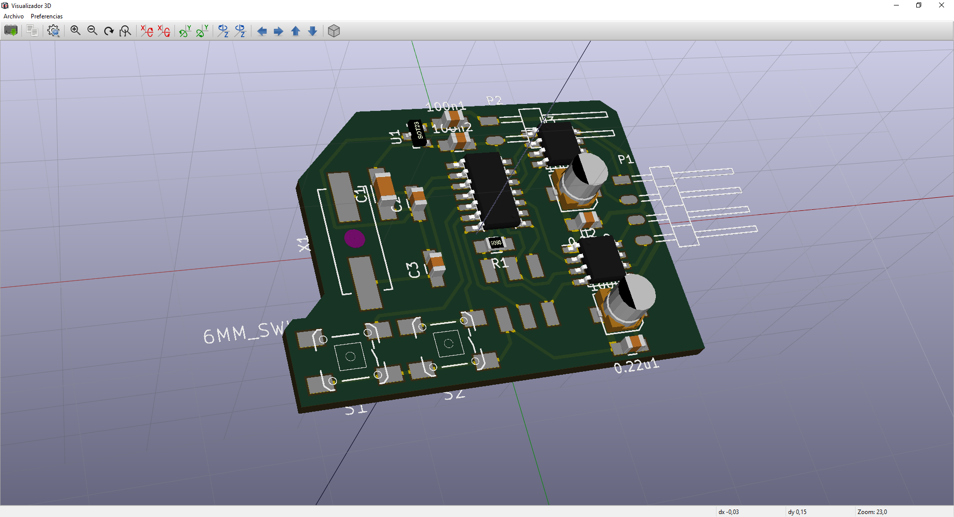
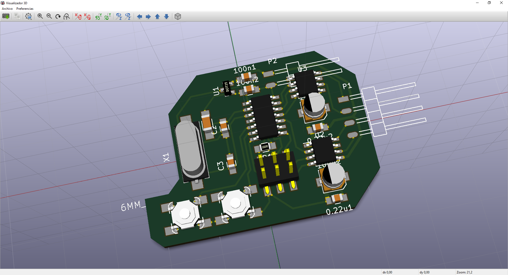
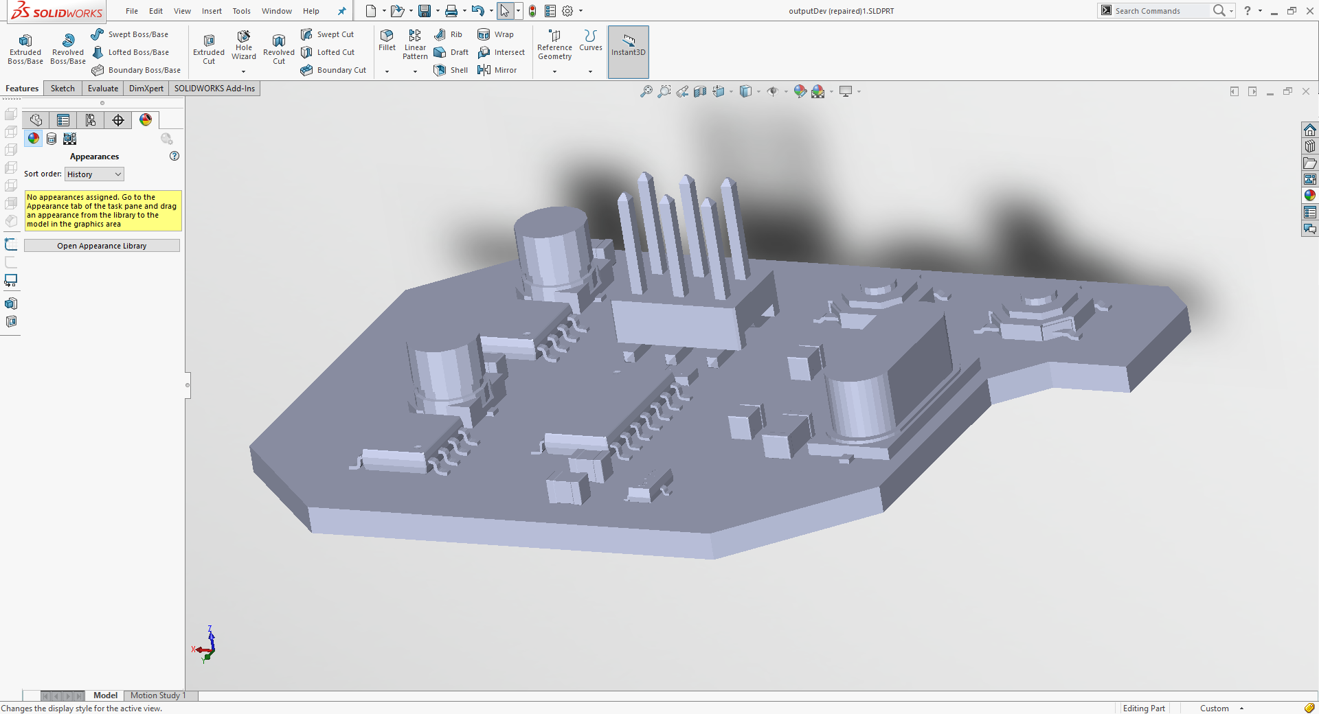
For this weeks board I want to control a bipolar stepper motor using a couple of A4953 available. Also, I keep testing features of KiCad like the 3D model output. For this week I want my board to be available as a solid on SolidWorks and make a case for it.
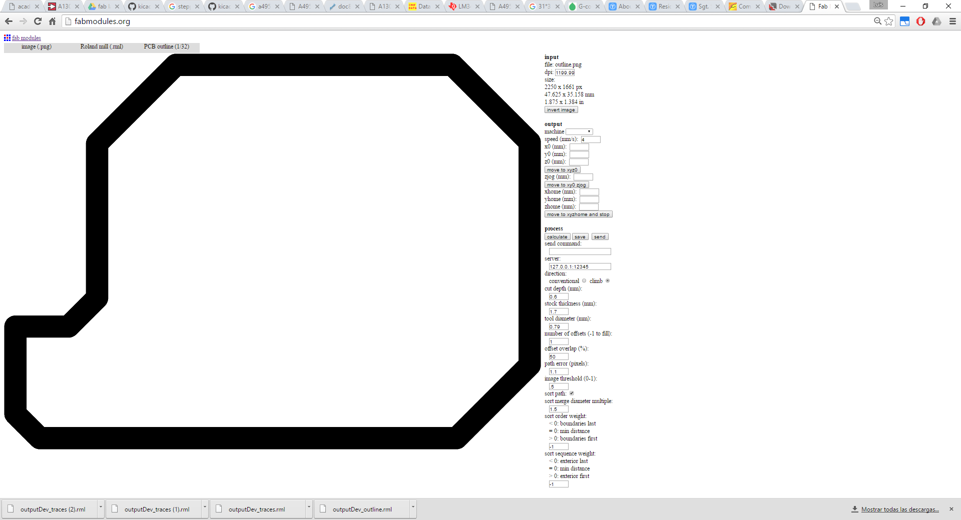
Also as something new for this week I want to make a non-rectangular shape to the board, just for testing a little bit more those issues with cutout in previous weeks. I'm going to generate both a square outline and shaped outline just in case.
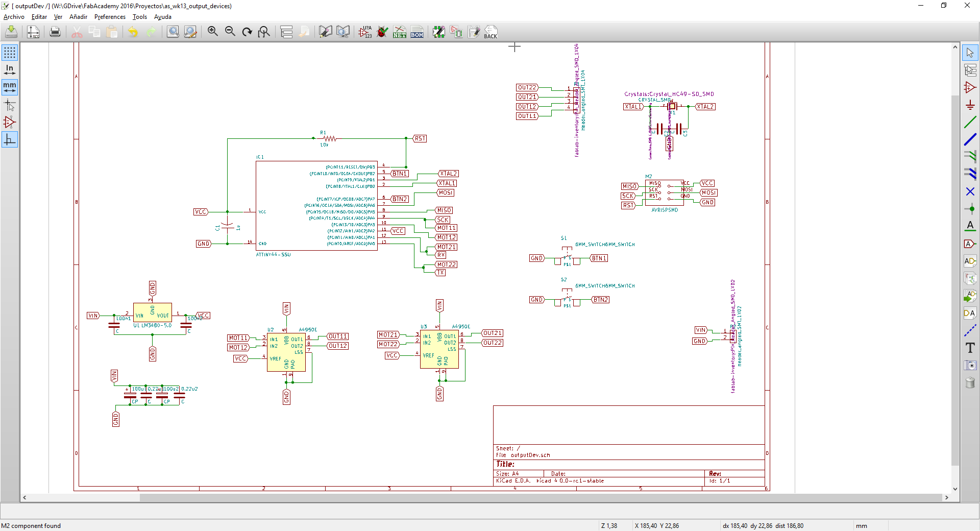
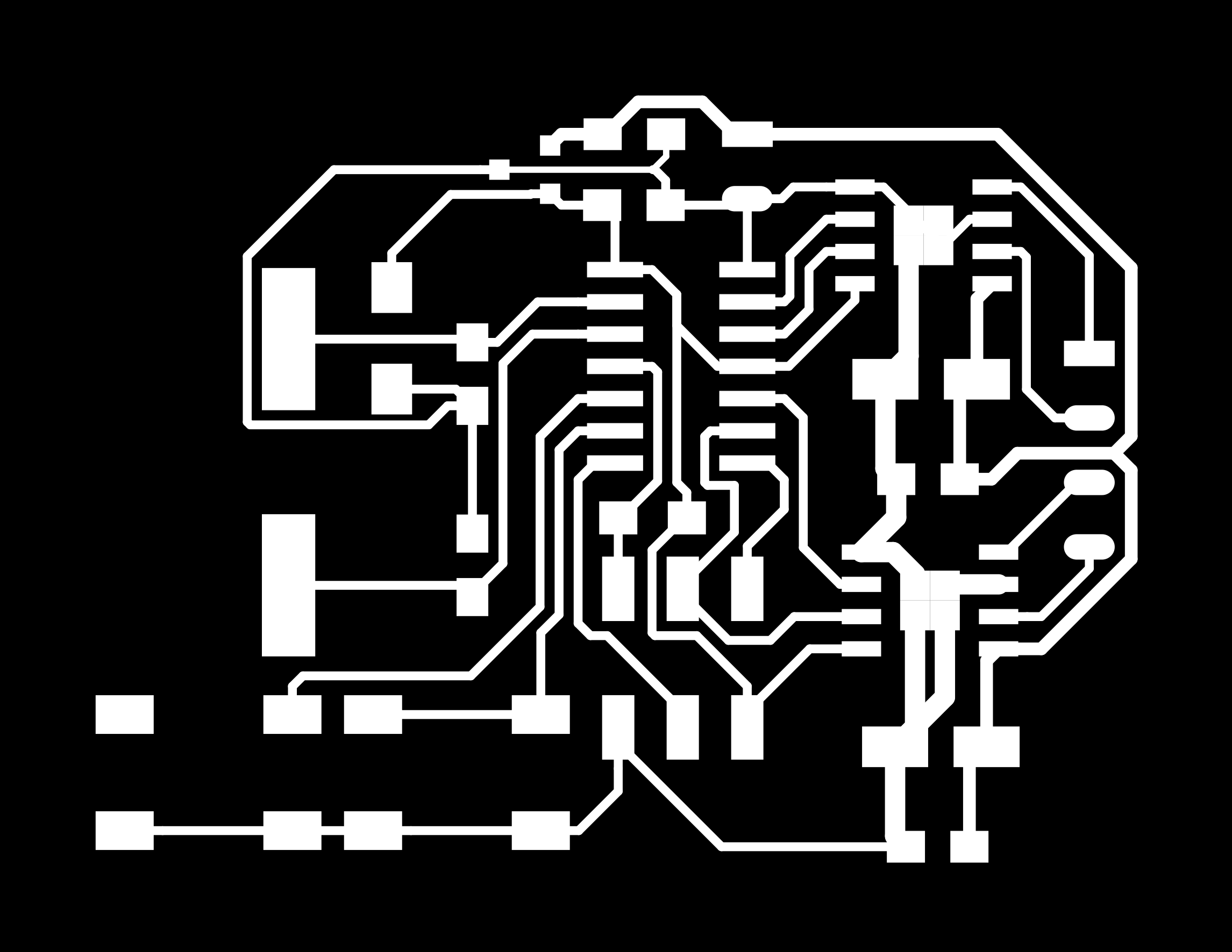
So first thing is to draw the schematic, I'm importing schematics from previous weeks and deleting and adding components, so for this week I added a couple of single coil drivers A4953 and a voltage regulator to get 5V from the 12V input that is also used for the motor. I kept the crystal and replaced the LED from week 6 for another button may be to program a movement switch operation. I've used SMD pads for the power supply and motor connection and maybe will hard-solder the motor or have a cable with a connector for that.
So from there I generated the netlist, chose the footprints using CvPcb and had to solve a couple of issues as I wanted to install the GitHub libraries and there was some trouble with paths. Library management is a bit painful but I'm getting to it.
For the PCB routing I took a look at Neil's board on how to place the drivers and noticed how he uses a µC pin that is not used to route another signal. Every board I'm routing, I'm loving KiCad more, I've found some cases where the interactive routing is great, I'm getting used to the OpenGL render and I'm now looking forward to test differential routing of data track (encouraged by David Pello) and start customizing keyboard shortcuts.
Some components have 3D models on KiCad core libraries, like IC packages, resistor, and capacitor packages, but others like the pushbutton are missing. Looking for models I've found this page http://smisioto.no-ip.org/ which has lots of footprint libraries with their 3D models.
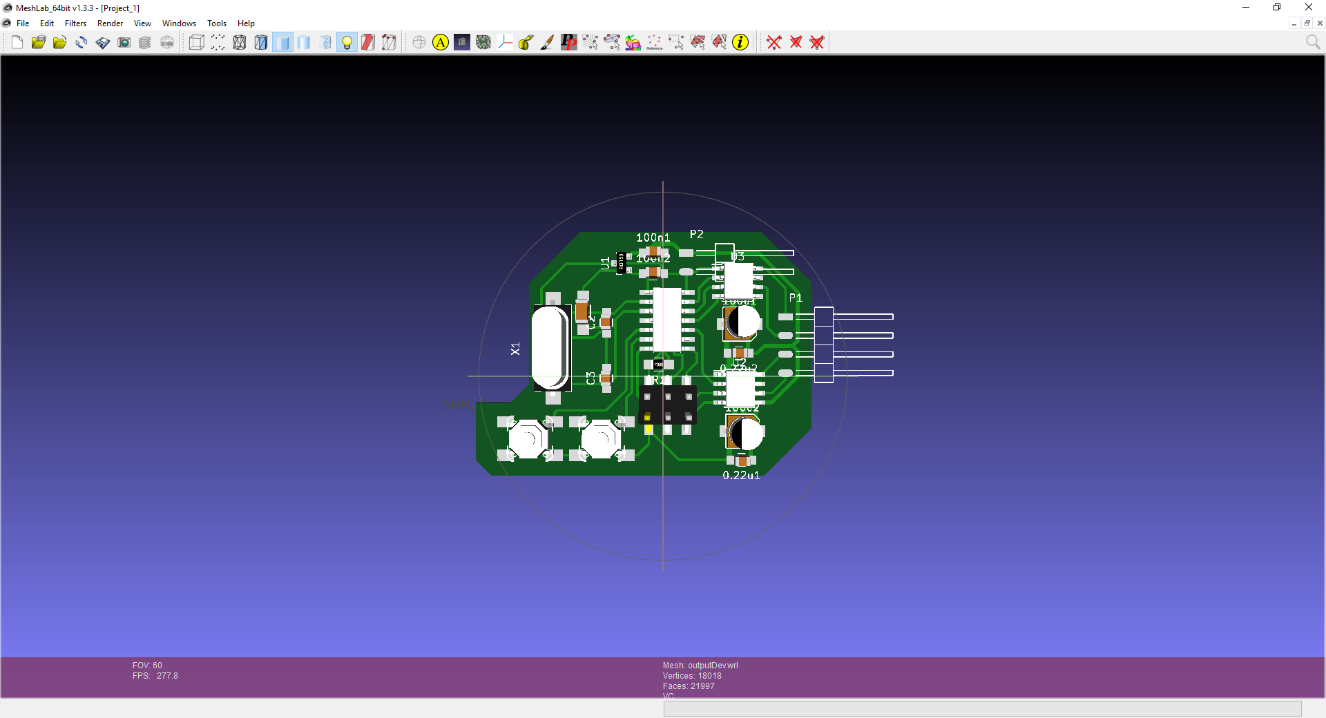
Once I got the model on KiCad I had to export it to use it with SolidWorks. Don't look for any export menu on the 3D view tool. Just got to Pcbnew, File->Export->VRML. I didn't read the whole VRML specification but it seems to export it as the board solid and some other geometries like the pads and silkscreen, plus a link to all the component models. Thing is that SolidWorks VRML processor does not follow those links and you end up with your unpopulated board as a solid. So, workaround, I got it to Meshlab, which loads the VRML property with all the links and the export it as .STL to get it on SolidWorks, it takes longer to write it than to do it.
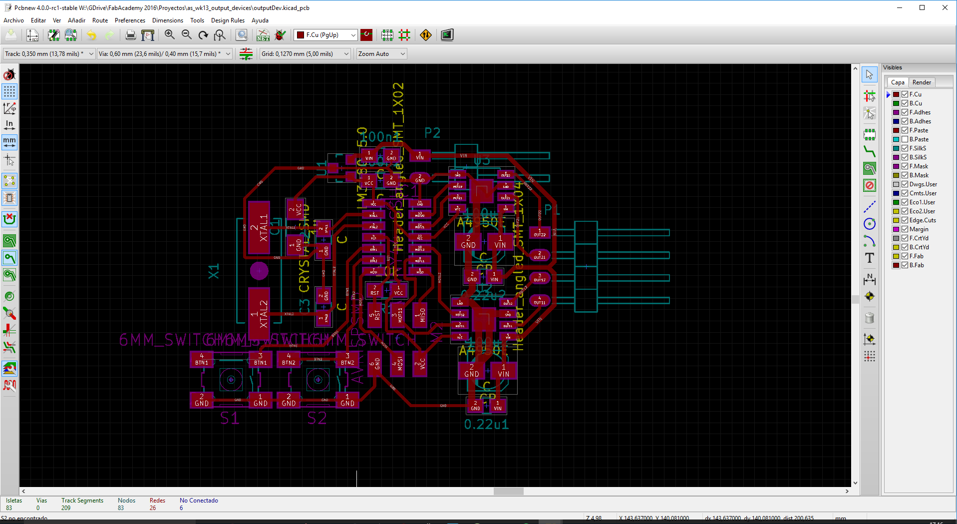
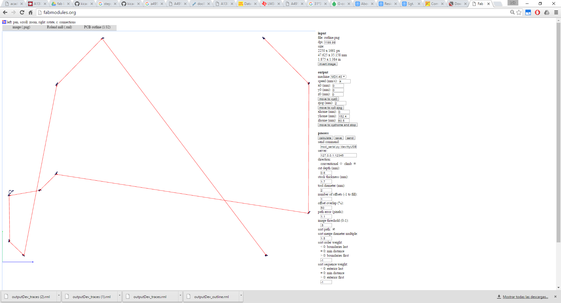
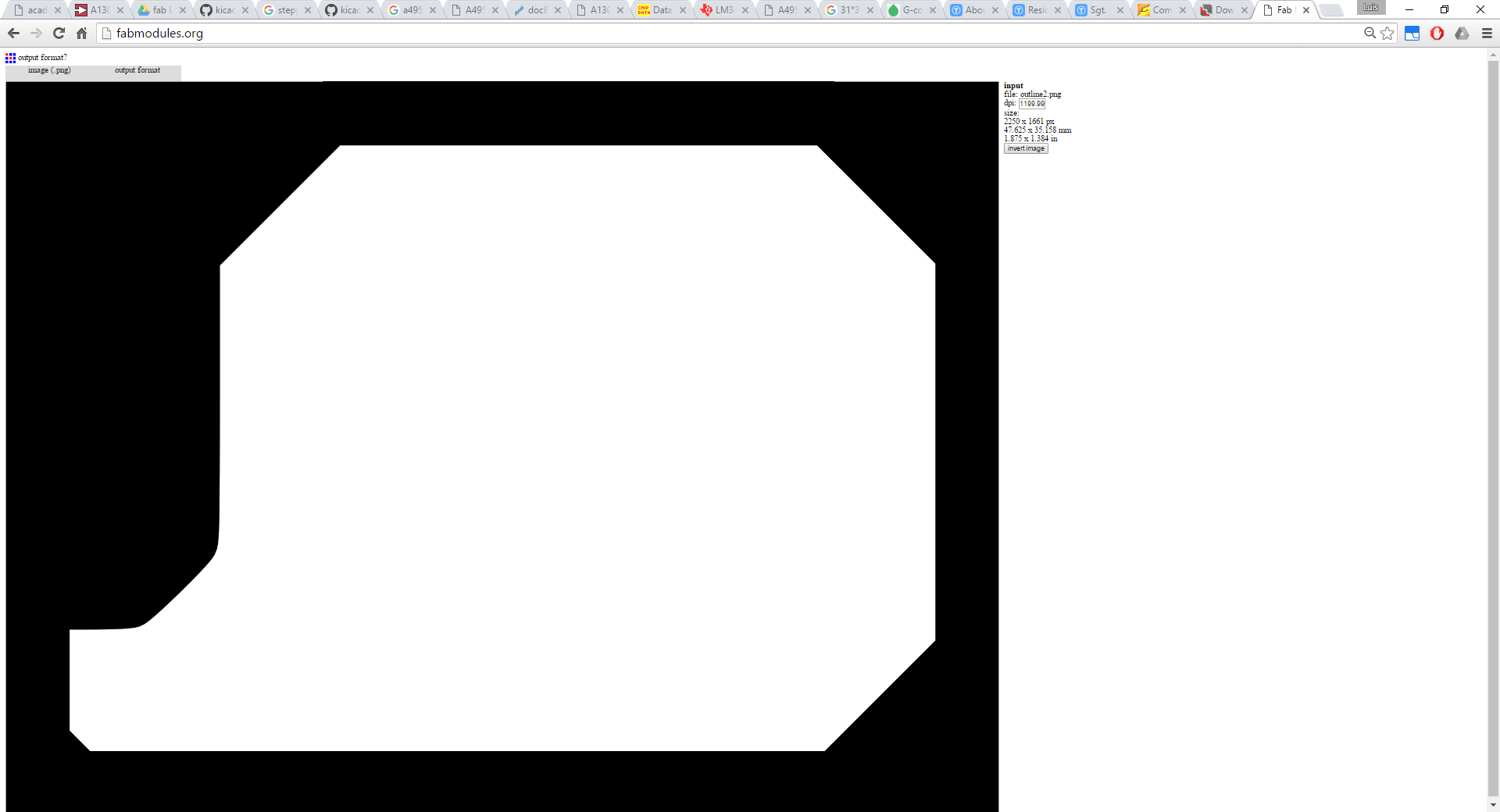
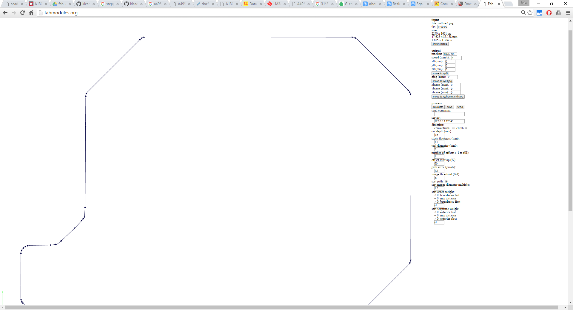
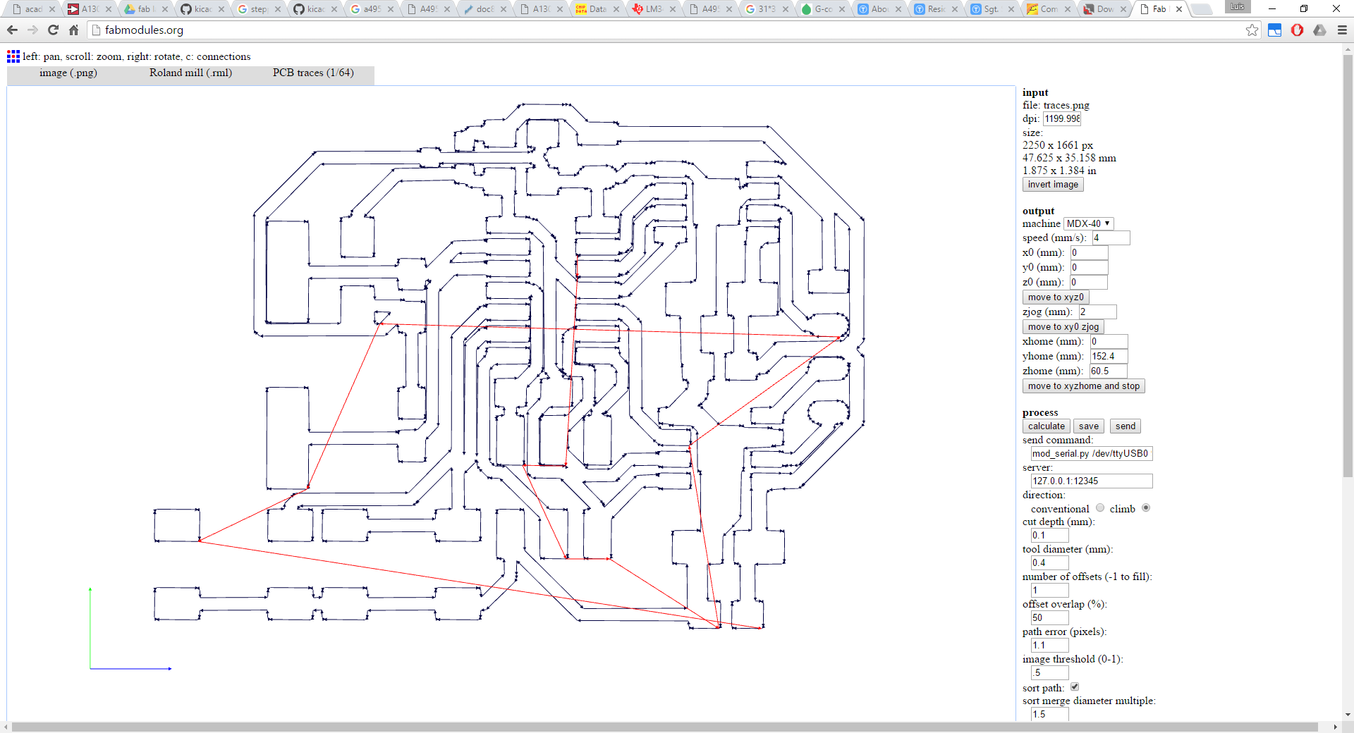
As for the board shape, for now, I just got the .rml files to get them milled on Tuesday afternoon. So this still needs to be validated by the MDX40. But basically, everything goes smoother everytime. For this week I wanted to try non-rectangular shapes and the shape of this board serves no concrete purpose other than just doing it. So I drew the outline on KiCad, 2mm thick and following the shape of the board. From there I exported the .svg and prepared everything with Inkscape
To be able to fill with black to the borders, I needed first to get a single object from the outline which is as you get them from KiCad, an object for each stroke. So select everything, select node editing tool, select all nodes, and then unite nodes. That way you get a closed single path that you can fill properly and combine with a bigger black rectangle the size of the total dimensions of the outline (max width and max height).
Still need to mill it and work on the code, hope it will be updated later this week.
Update: It's taking me too long to get this board right, first I had some trouble with a bad outline cut design I had, with some extra black filling on the inside that ruined the traces. Then after getting that right I realize that there are some joined traces that shouldn't be. Design rules in KiCad are just right, so has to be a bit of re-scaling in some part of the process. I got another "fresh" SVG out of KiCad and I plan to mill it on Monday that I'm also visiting Fab Lab León for the composites assignment.
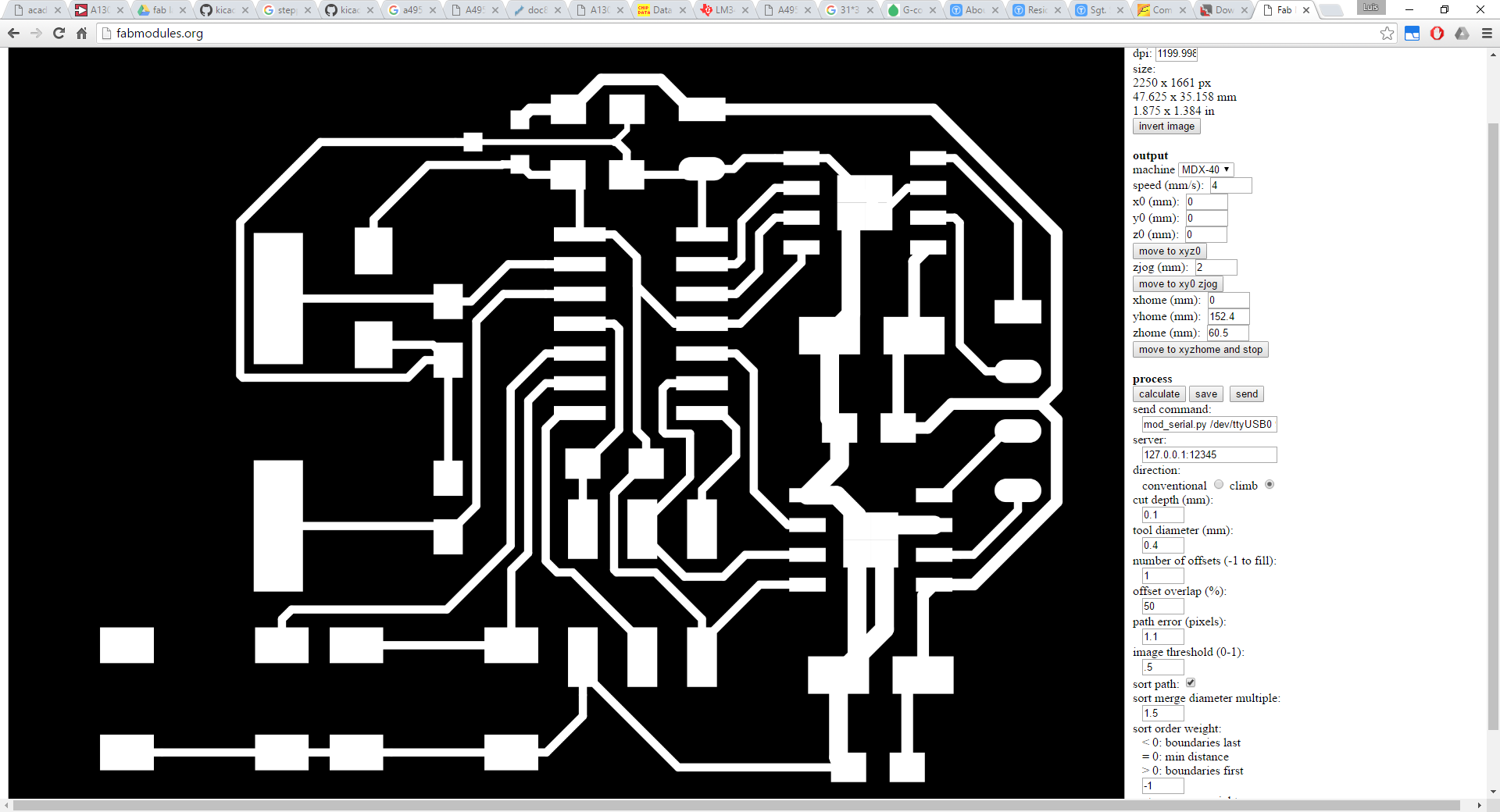
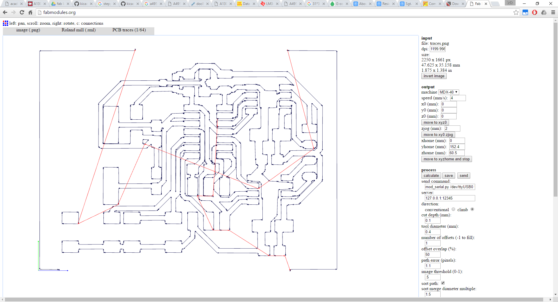
Update: after coming from Fab Lab León and milling the board again. I realized with this board, that my design rule of 0.4mm between traces was bad, as 16mil are 0.4064mm!!! I'm still surprised that this issue didn't come up with the previous boards. But this happened after another thing, I was checking the scaling of the board to manufacture a new one at León when I realized that there were no scaling problems. What I've noticed is that if I exported just the traces, black over white and inverted it with fabmodules.org, even though there were still some traces together, it was just a couple, not all those I had on my first board. But if I took the whole process and put white over black out of Inkscape, I had more non-traced lines that joined different traces. Then Nuria suggested about the mil to mm conversion and just updated my KiCad design rules to increase the distance between tracks. So after a couple of minutes of re-routing I got my new board ready and in the process I learned the workflow for using the MDX20 with fabmodules offline. Truth is that this Monday at León was great despite the fail with the composites.
.jpg)
.jpg)
.jpg)
.jpg)
.jpg)
.jpg)
.jpg)
.jpg)
.jpg)
.jpg)
.jpg)
.jpg)
.jpg)
.jpg)
.jpg)
One thing pending from week 8 was to use Atmel Studio for programming. So programming the board this week is going to be done trough Atmel Studio using an AVRISP mkII. So after a while getting the right drivers to work for the AVRISP to get recognized properly on windows I had the environment ready for testing. I started with an executable program for AVR but one option was to go as an Arduino sketch. I don't know yet if this is for Arduino only or it would allow to use Arduino library for programming other uCs. Anyway, I'll test the Arduino programming with Atmel Studio as the Arduino IDE is great so newbies don't freak out in the presence of a real IDE, but there are so many features that I miss in Arduino's IDE, starting with a simple auto-complete. And I think that even code-folding is a recent feature of the 1.5 or 1.6 versions. You can get other IDEs for Arduino.
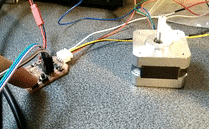
For testing the board I've used Neil's hello.stepper code and modified it to drive the motor forward and backwards using the push switches.
Machines and software used
SO: Windows 10KiCad
Roland Modela vPanel
Roland Modela MDX40
0.4mm PCB routing mill (traces)
2mm PCB routing mill (outline)
Files
Kicad
outputDev.pro
outputDev.sch
outputDev.kicad_pcb
Board
outputDev_outline.png
outputDev_traces.png
Code
outputDev.c
makefile