I'm going to try to make documentation a bit more of a diary this week. We currently have six FDM printers at LABoral, 3 RepRaps, and 3 Ultimakers 2+. Two of the RepRaps are based on BCN3D RepRapBCN, one of the first models if not the first from this company based in Barcelona, and have little modifications as original SolidWorks files were available for this model. The other one is a P3Steel, which is a Prusa i3 with zinc steel frame.
The Ultimakers are the most recent ones and they are not yet at the fabLAB but in the main exhibition room as part of the exhibition Materia Prima. This exhibition commissioned by Gehrfried Stocker is part of the EDASN project and as a way to take new artistic processes to the public, a series of labs are part of the exhibition area, one being the Fab Lab. This mini Fab Lab is equipped with a 400x300 mm laser cutter, an Ultimaker 2, an Ultimaker Go! and a BQ Ciclops scanner. The other Ultimaker 2 is used by the educational program or for other activities and I can take it this week
So for the printing adjustment assignment I'm planning on using one of the Ultimakers which I didn't really full-tested because they arrived the same week of the inauguration. But what I've printed with them is awesome, we just had a bit of a problem with the extruder pressure on the filament. And I'm really looking forward to print with them as fast as possible.
Now for what I've done with 3D printers even though I've never fully assembled one:
I've leveled beds, and that's on of the worst things on some printers, a bad leveling mechanism could be a bit frustrating. I've found this design to be very useful to check on a bed, even for live adjusting. Also other usual maintenance and some nozzle/extruder change.
I've printed PLA most of the time, but also ABS. PLA is so easy to print, ABS is so tough...
I've explained 3D printing at the fabLAB sooo many times, and I subscribe what is said that people come to the Fab Lab for the 3D printer, but the stay and come back for the laser cutter. I had even written a post about it, when we thought that two people would be able to handle our level of activity AND write a weekly post, both in Spanish and English for the blog, sorry, we had to drop it.
I've printed some lithophanes most of them of Tesla. I had them around the fabLAB and it was very funny how people would approach to them, take a look and think "what an horrible print" and then when we see them we tell them to look at it with some light in the background and their faces change drastically.
I've printed an RC plane's tail stabilizer both horizontal and vertical sections, with independent control surfaces, trying with 4% to 7% infill. But these are not tested in flight. I've tried different fill patterns being linear the one that made the best inner structure.
I've used Cura and Slic3r most of the time. Cura for when you just need to print something, and Slic3r when you want to be in control of everything and run tests or print more complicated designs. One of the main uses of Slic3r for me is the ability to define a modifier volume with different parameters here there is a great tutorial., I'll try to make a tutorial about this using SolidWorks. But basically, what you need is to put the part you want to make an assembly and save each part as an independent STL file from that assembly. That way it will keep the relative coordinates and you'll have the modifier where you wanted.
On 3D scanning I've also fulfilled the assignment, but of course, I'll try to make something different this week. When we were preparing the Fab Lab for the exhibition Materia Prima, we had for a couple of weeks a MakerBot Digitizer and I've was very interested in having this on the exhibition because it filled the whole ABC/BAC process (Atom to Bit Converter, Bit to Atom Converter) and we could be able to interact with other labs in other exhibitions trough file exchange of hand modeled models. So I started testing the scanner, and it was bad, bad but enough for what we wanted. We didn't have the money to get the MakerBot Digitizer, but the BQ Ciclops is quite affordable and we decided to get it. I had one week to test it before the exhibition. And the conclusion was that the Digitizer didn't let you have many options and the scans were not always good, but you could get some scans ready to print. With the Ciclops you'll have to acquire the mesh on one software and then you can use another couple applications to close the mesh, and it takes a lot of trial and error to get a printable file out of that. This remember was just after a week of testing and not full time at all.
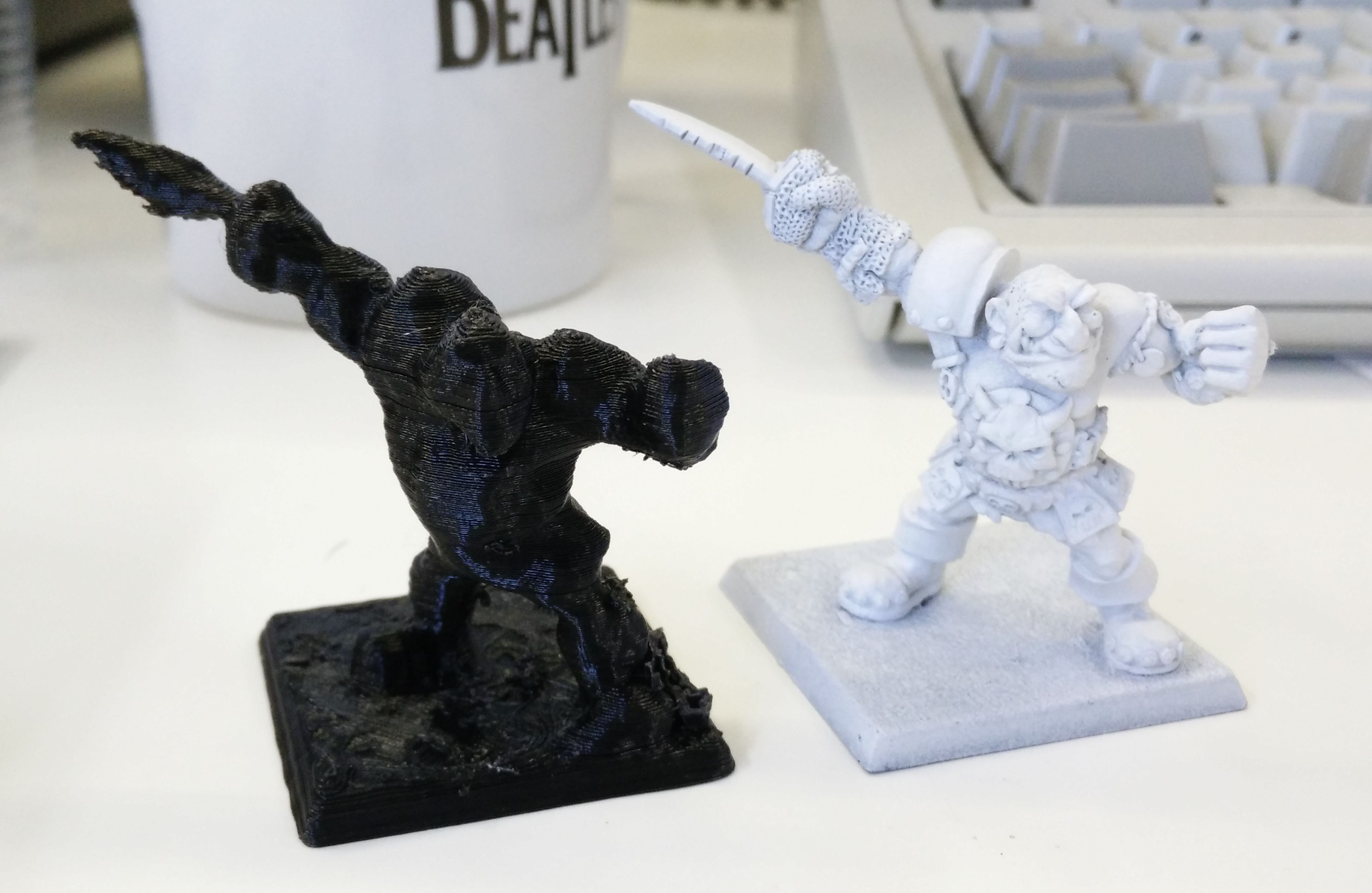
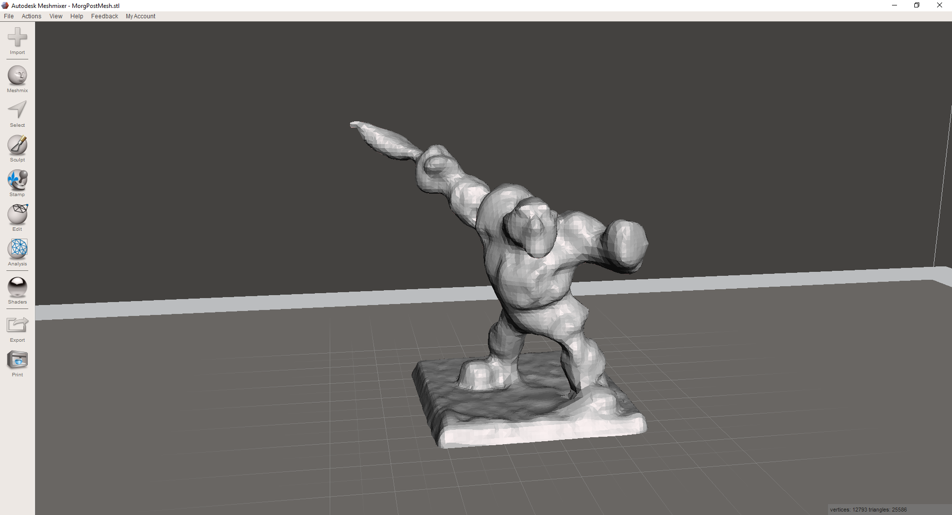
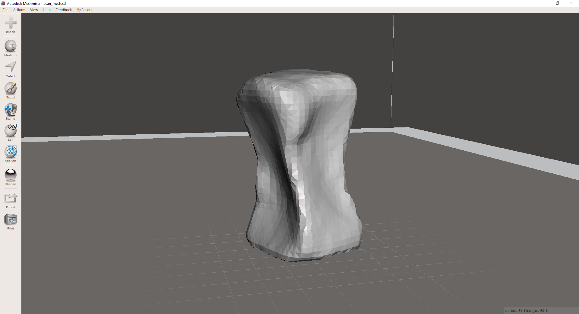
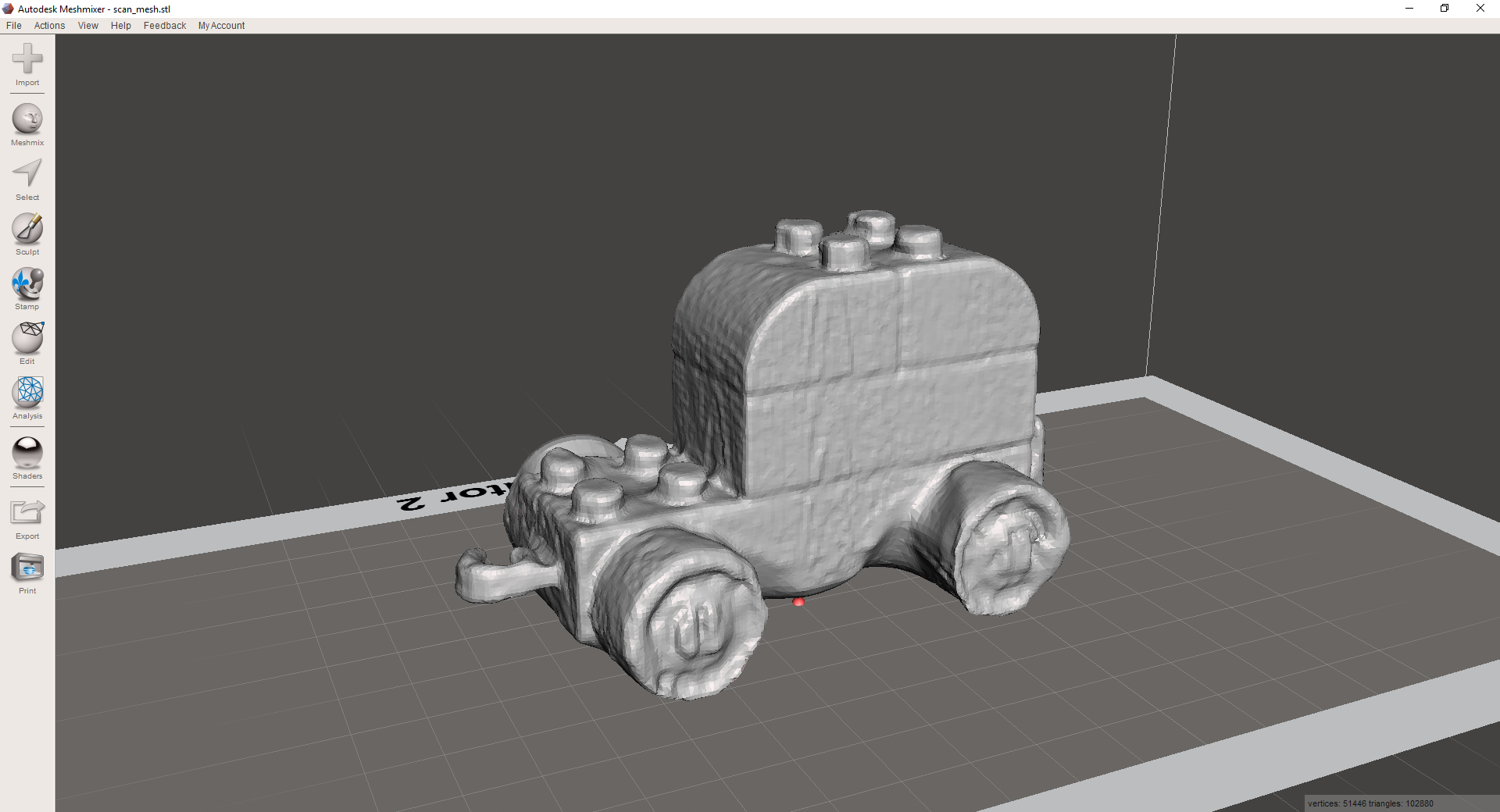
I've scanned several things and I have to look for files, but what I once scanned and printed miniature of Morgh'n'Thorgh, from a miniature-based boardgame called Blood Bowl. It was white primed, and that always worked the best obviously, as black and dark colours would absorb too much from the laser and can leave empty holes (the camera, sees just black, no line). I've also printed it, and the result was way better than I expected, you could at least identify the miniature. I've also tried with smaller miniatures from the same game and they were just ugly blobs. I can show pictures of the scans but not the scan files as this was made with educational and testing purpose and would be violating copyright if I publish them. Well after reading that, let's just say that I don't have it on my desk and that I've destroyed it as soon as I took the picture.
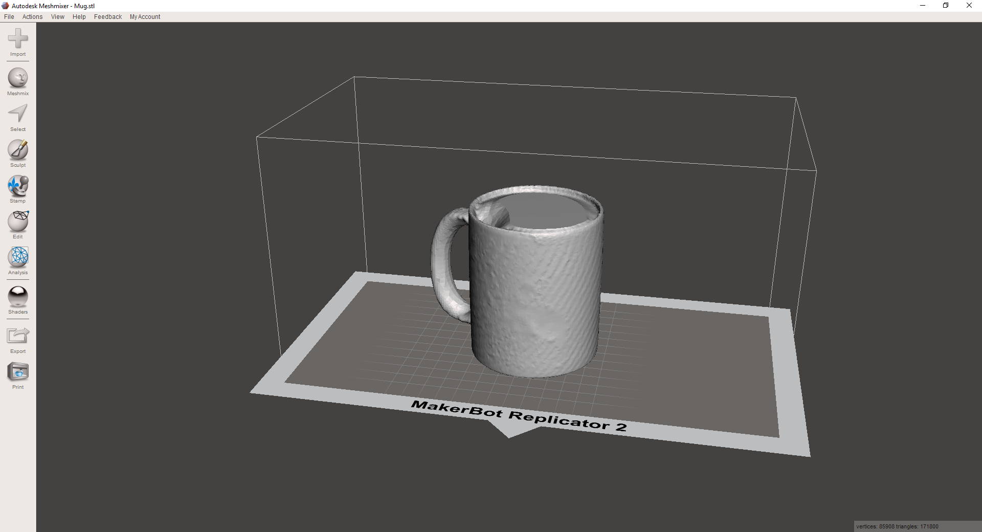
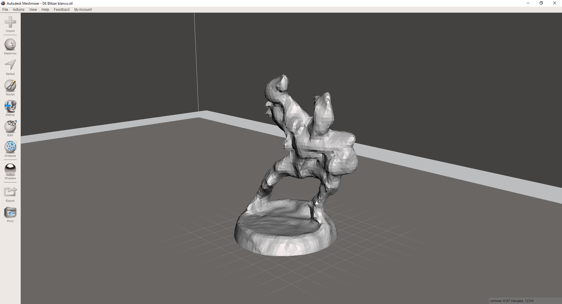
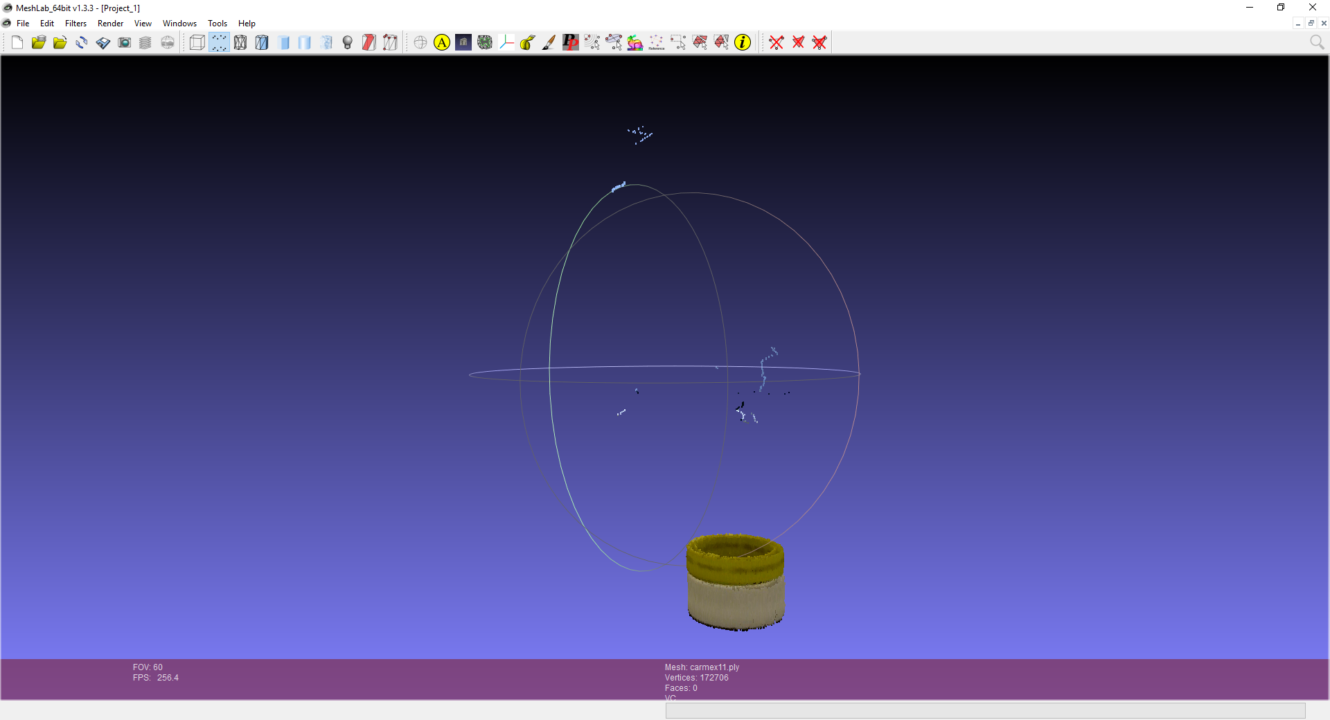
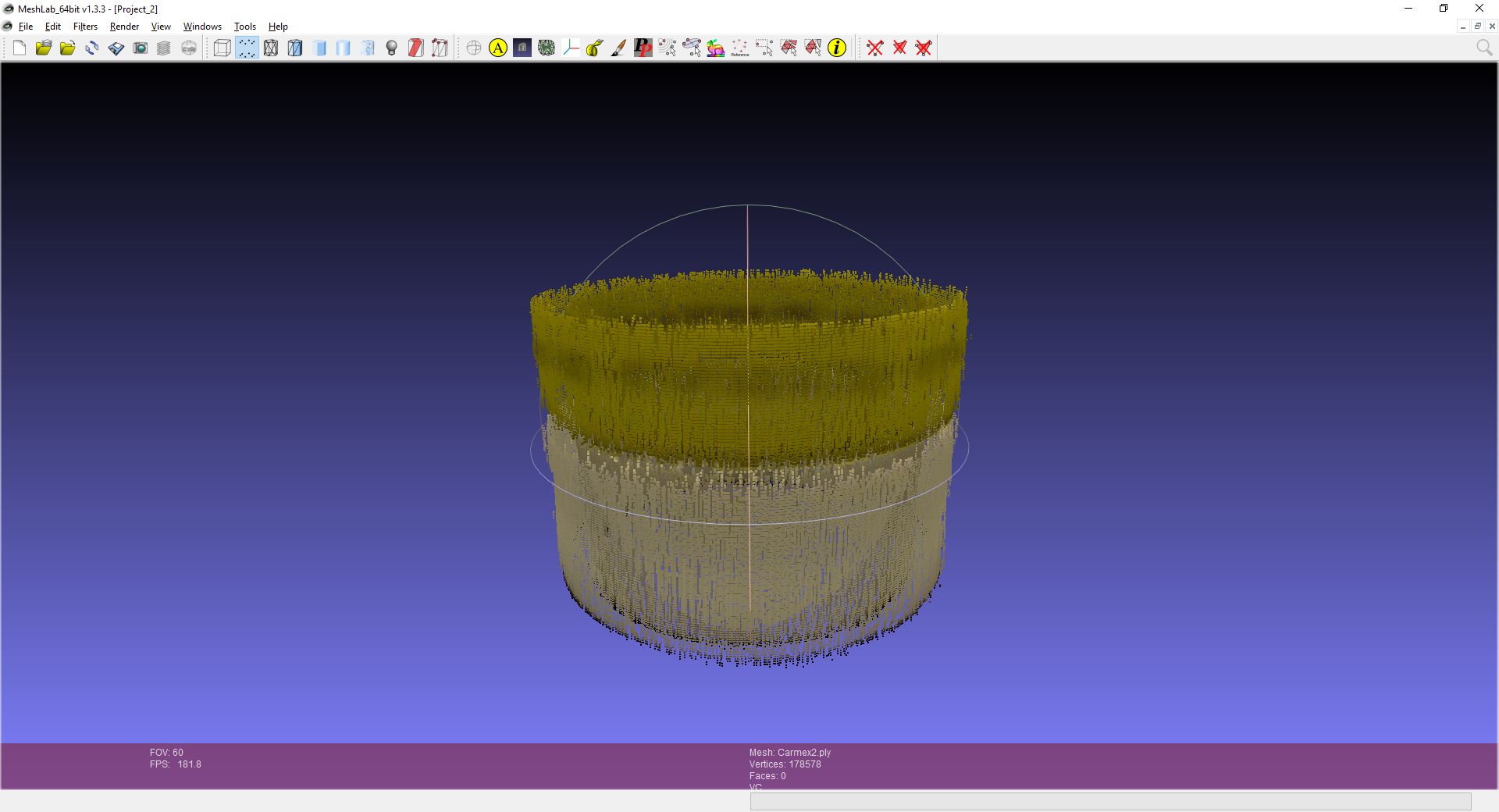
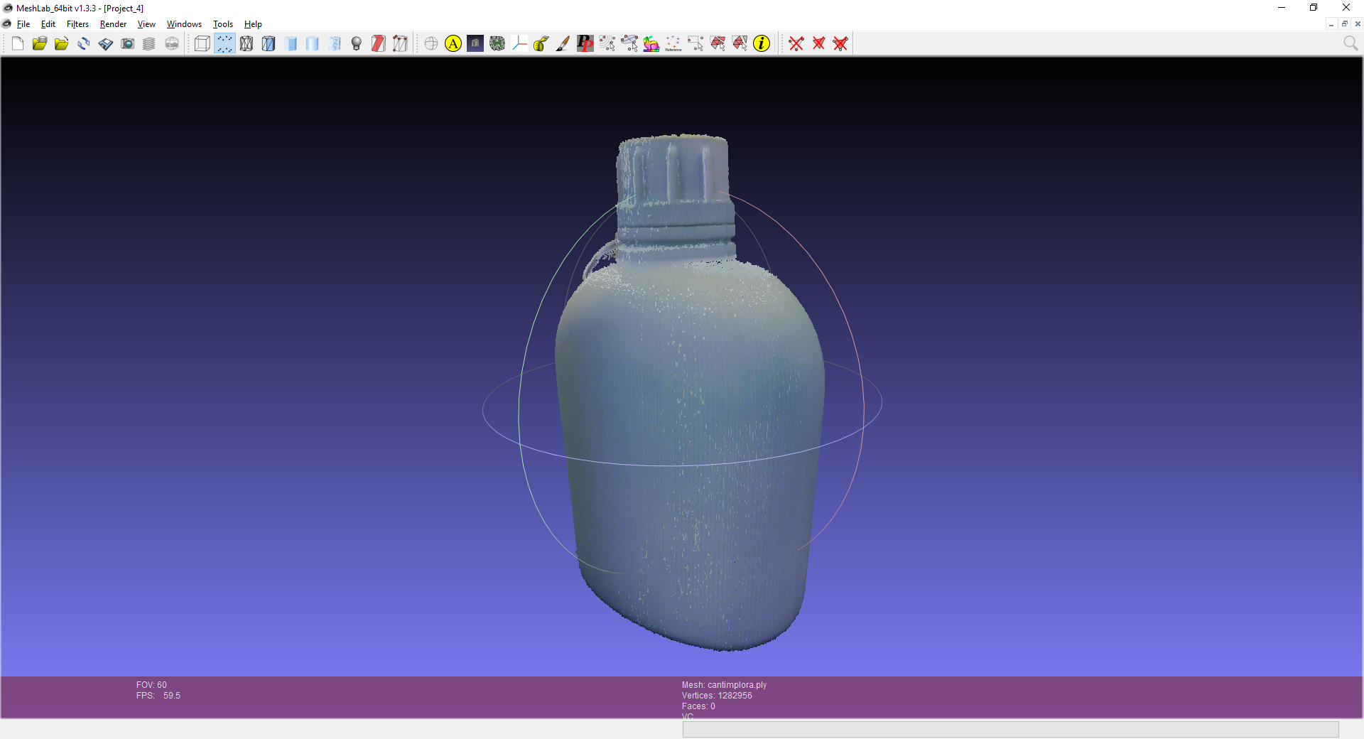
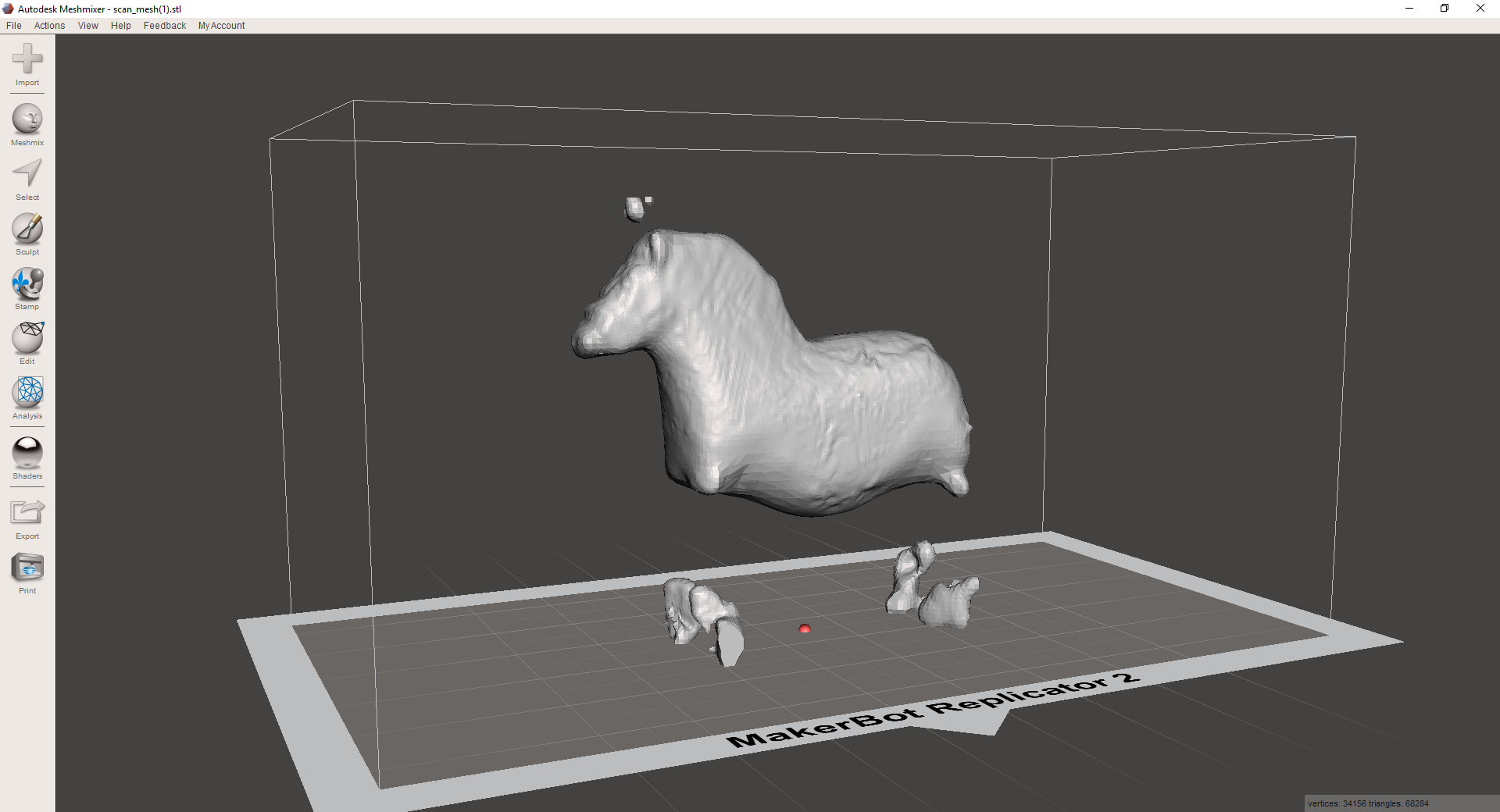
Update, here are the scans, the ones visualized with Meshmixer are .STL from Makerbot digitizer, the ones viewed with Mesh are point clouds (.ply) from BQ Ciclop
As for modeling, I usually model mechanical parts, and I think most of the parts I've modeled for printing were feasible with other non-additive techniques. So this is really the only non-completed assignment of the week.
So thinking about an additive-only geometry I came with two basic ideas, a Delaunay-Voronoi-like volume that I know can be made with Meshmixer, or an already assembled mechanism like the typical hinge or gears.
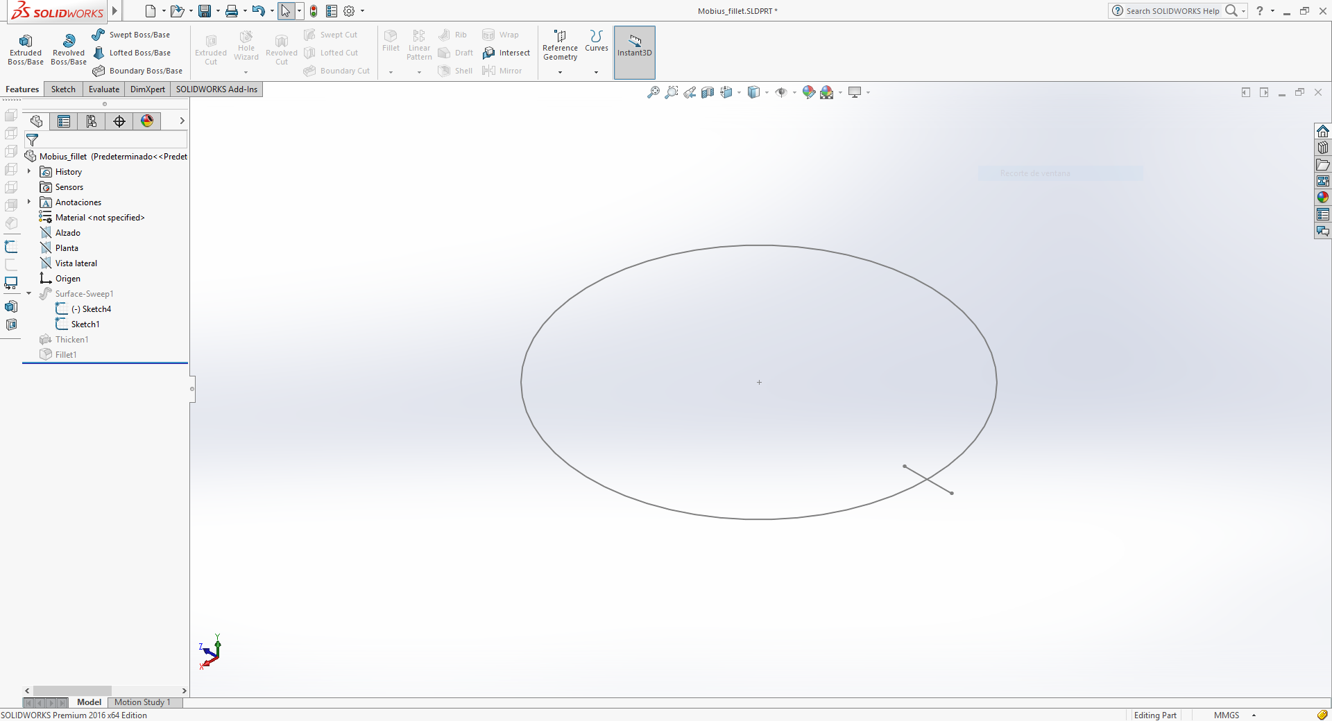
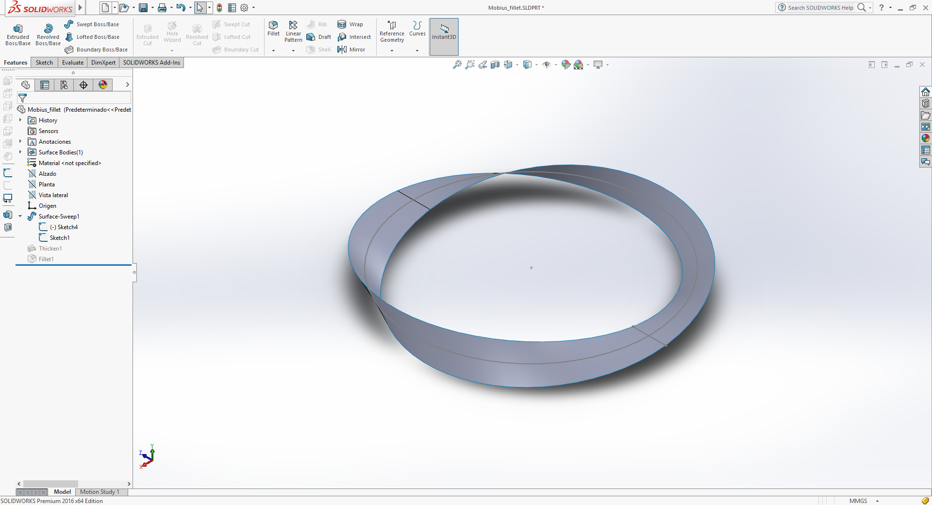
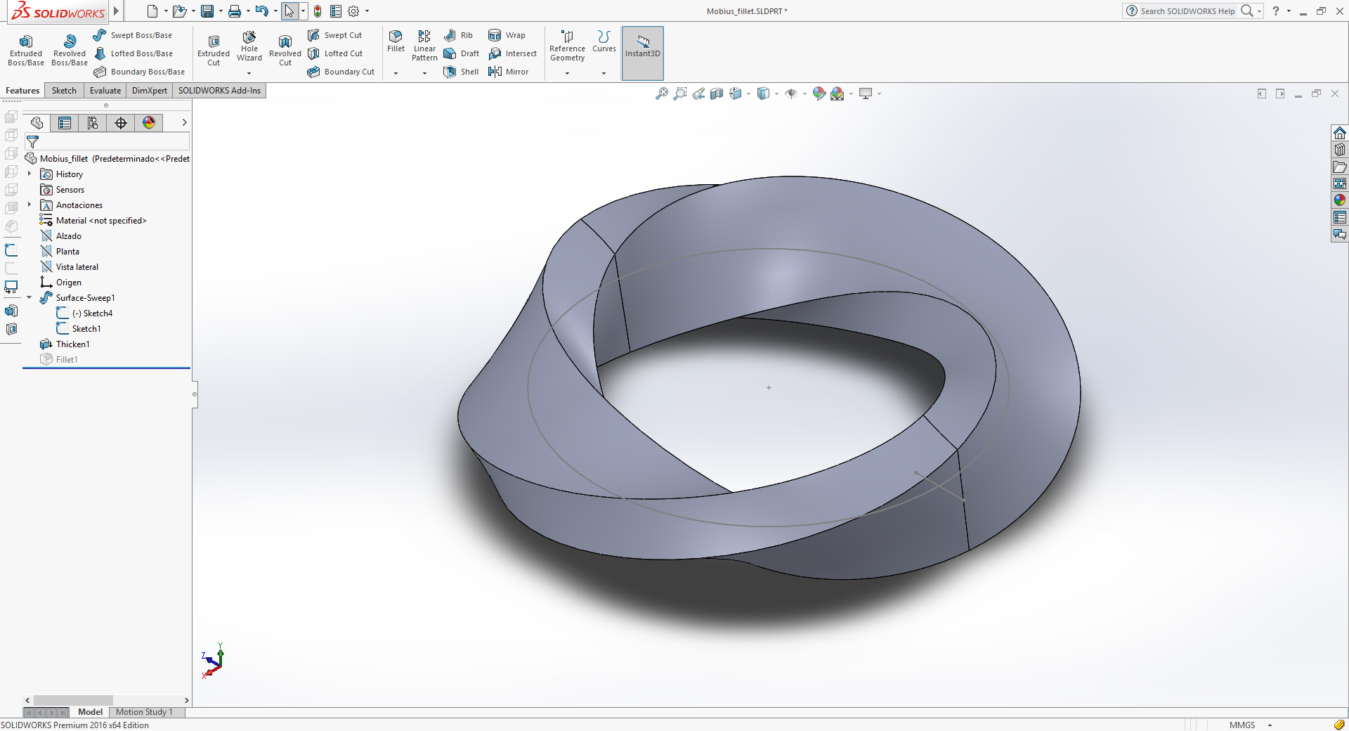
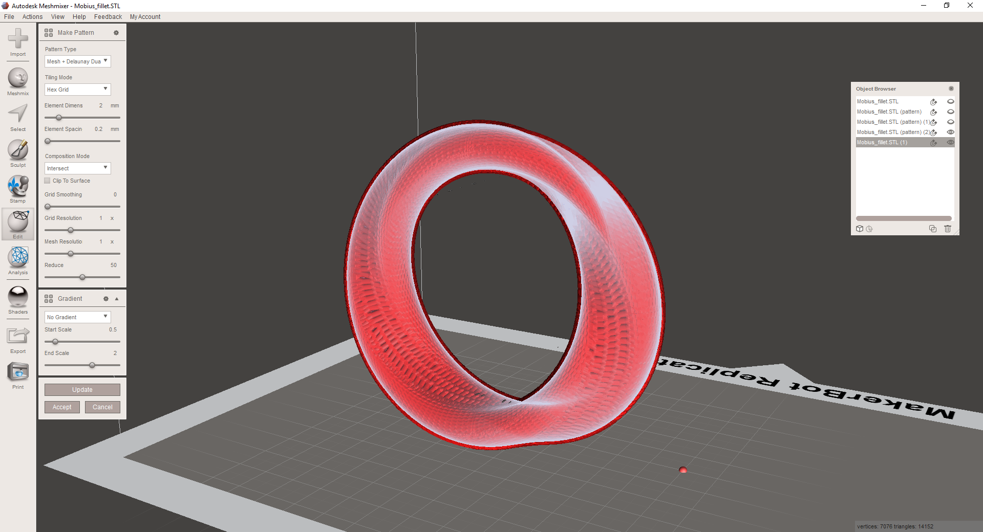
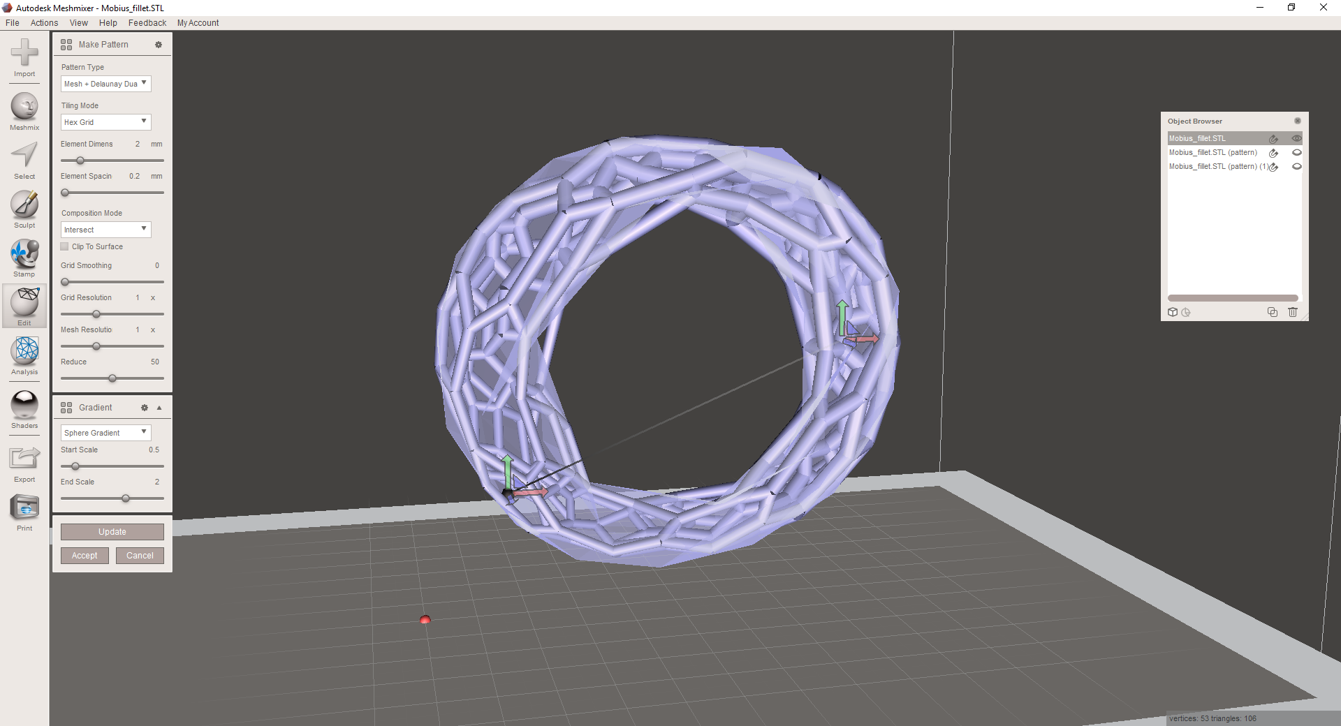
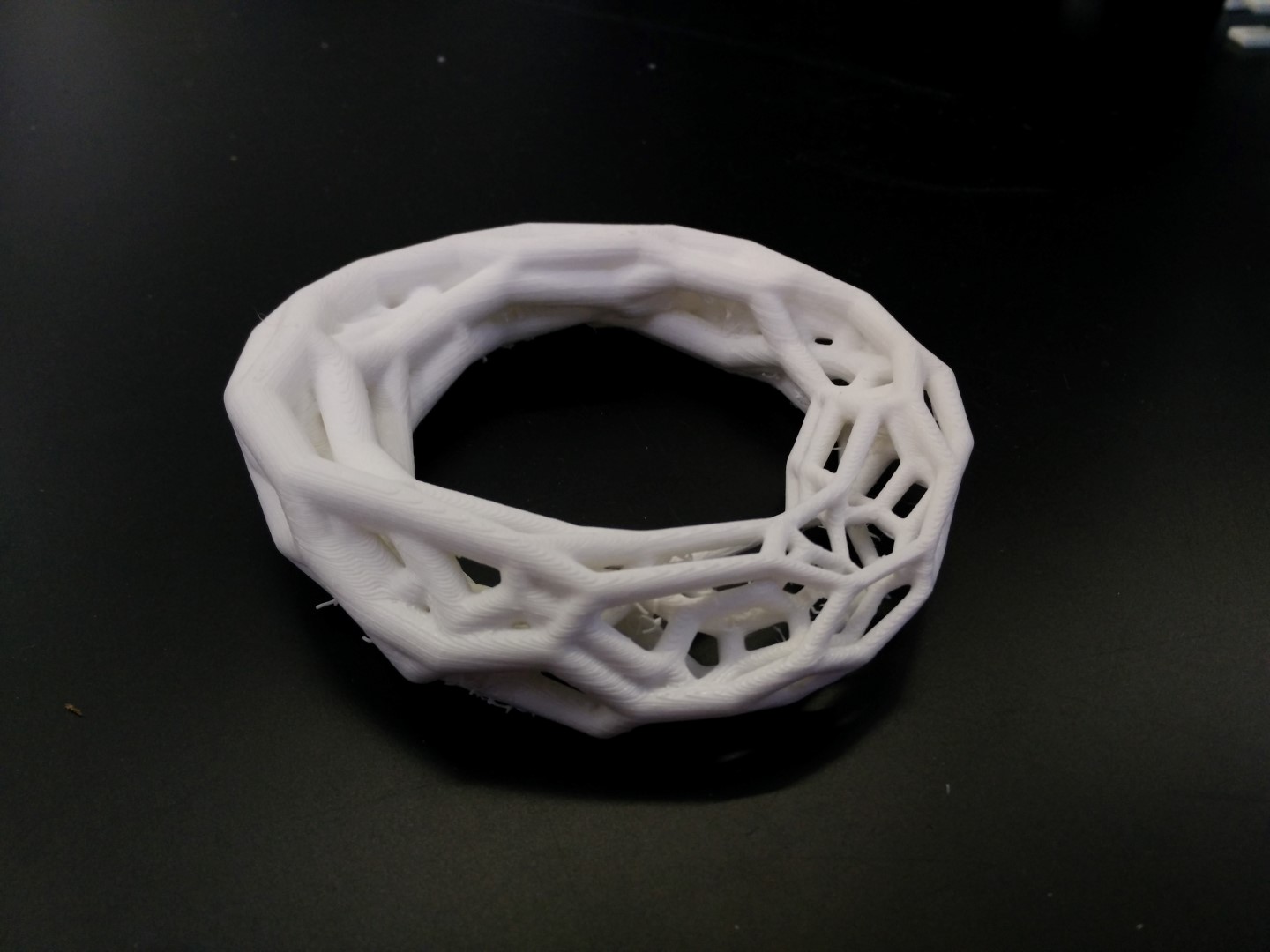
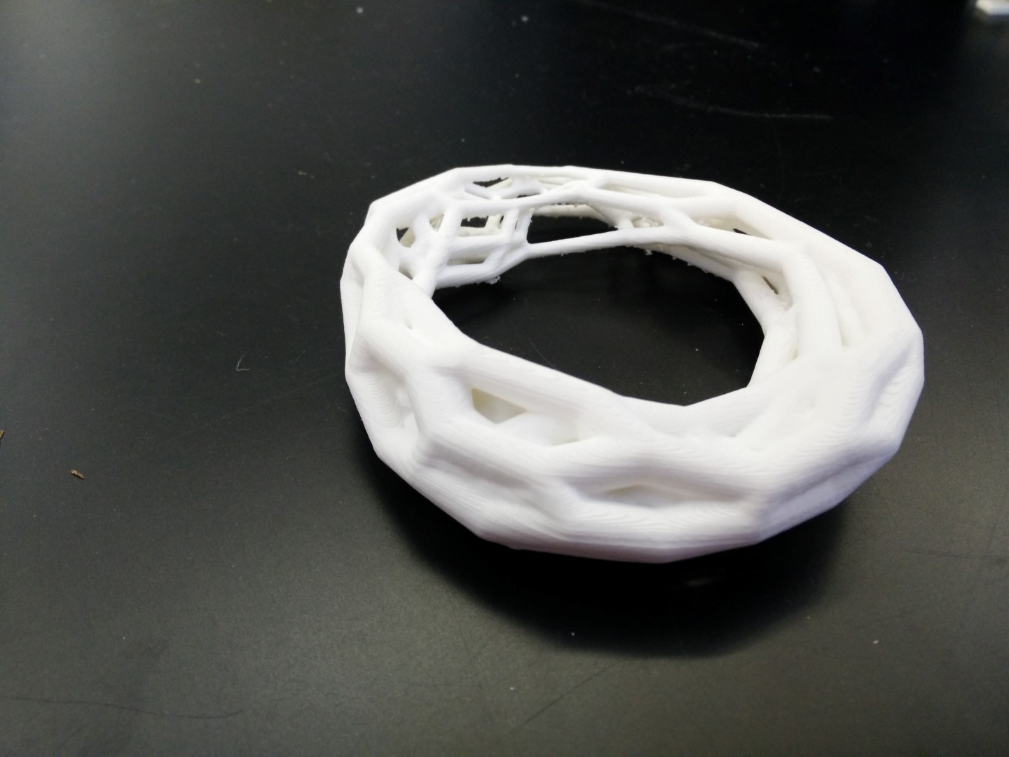
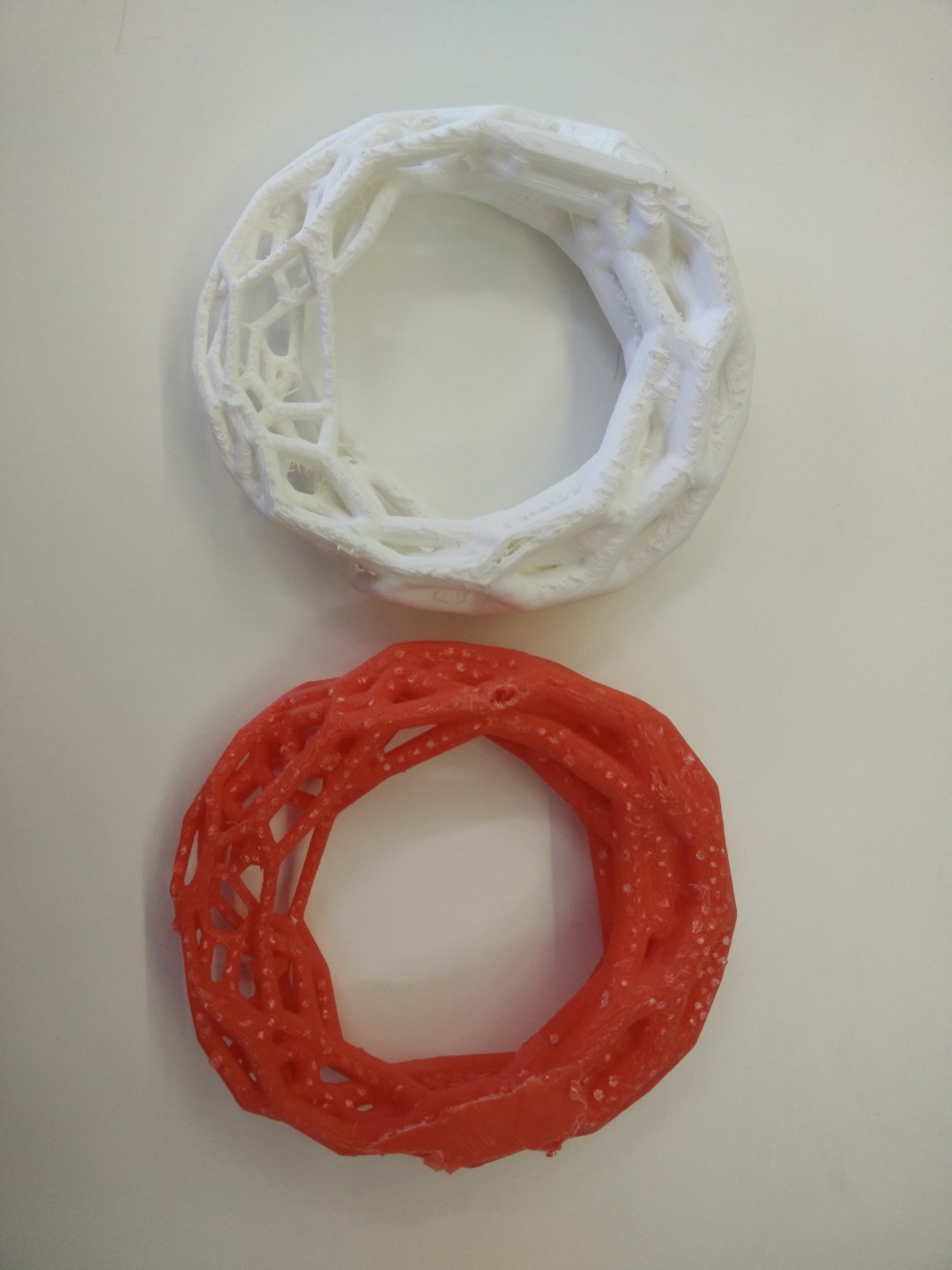
I've started modeling the solid for the Voronoi operation because I didn't get the design rules for how close walls can be without sticking to each other. I have a 3D printed Klein's bottle with a Voronoi pattern on my desk, which I printed to test Eumakers filament when they sent a free spool to our Fab Lab. So thinking of completing the collection of non-orientable surfaces printed with Voronoi patterns, I went to SolidWorks to model a Möbius strip. The process of thickening this non-orientable surfaces makes them in fact orientable surfaces, but the shapes are beautiful.
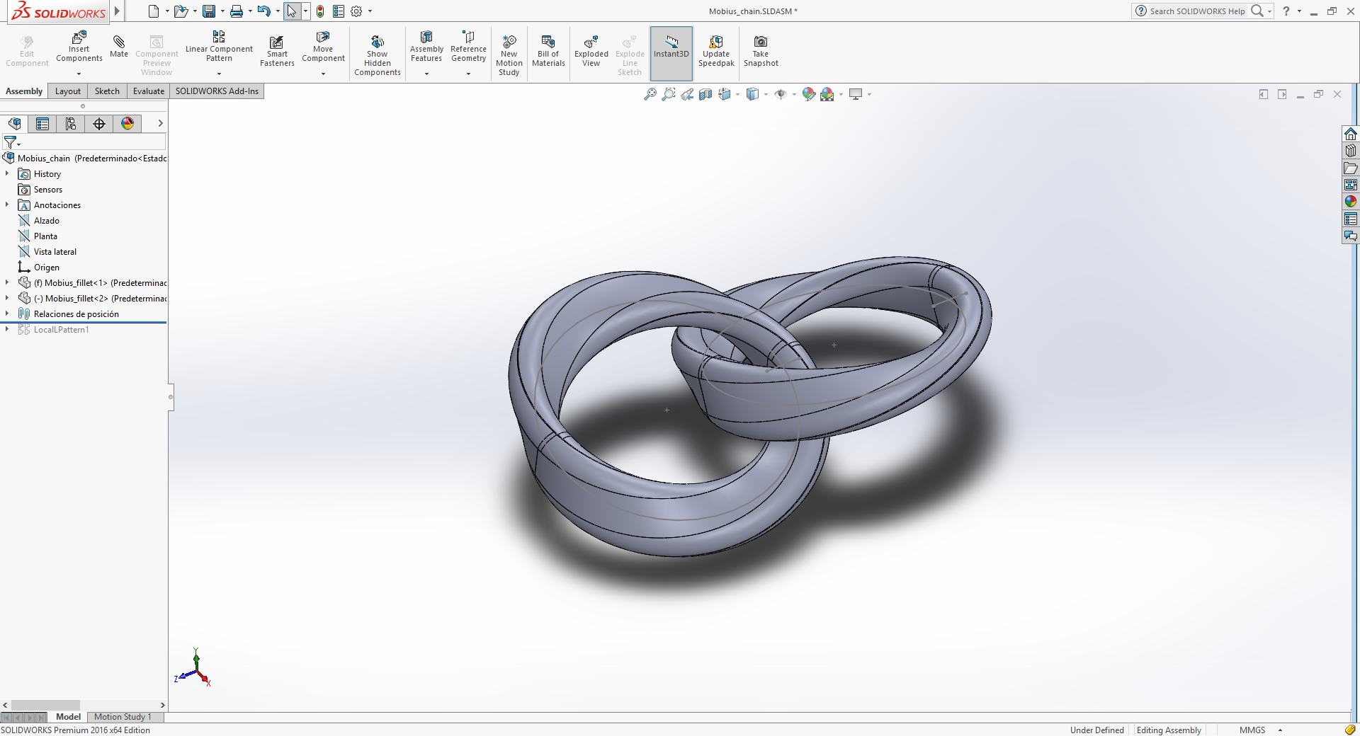
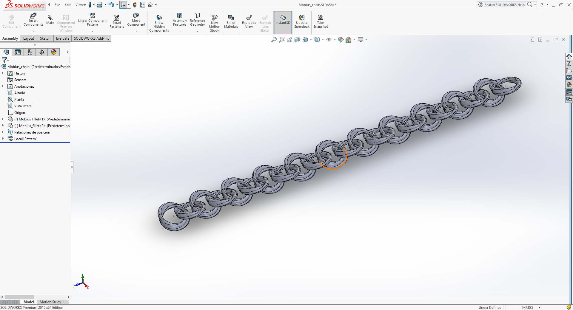
This is the modeling on SolidWorks:

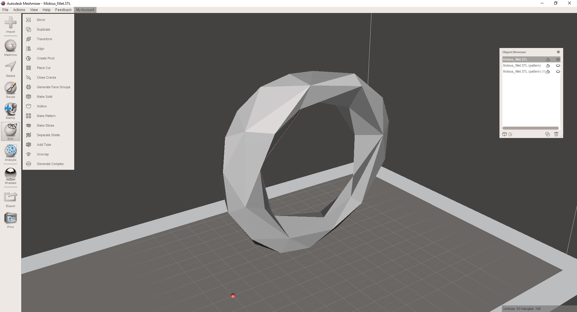
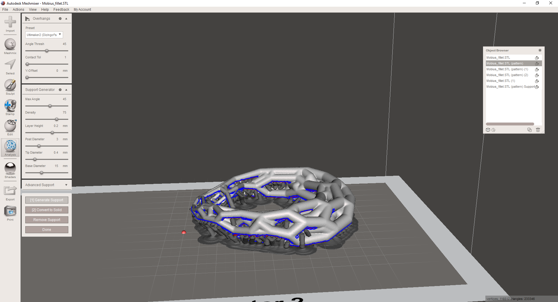
Meshmixer
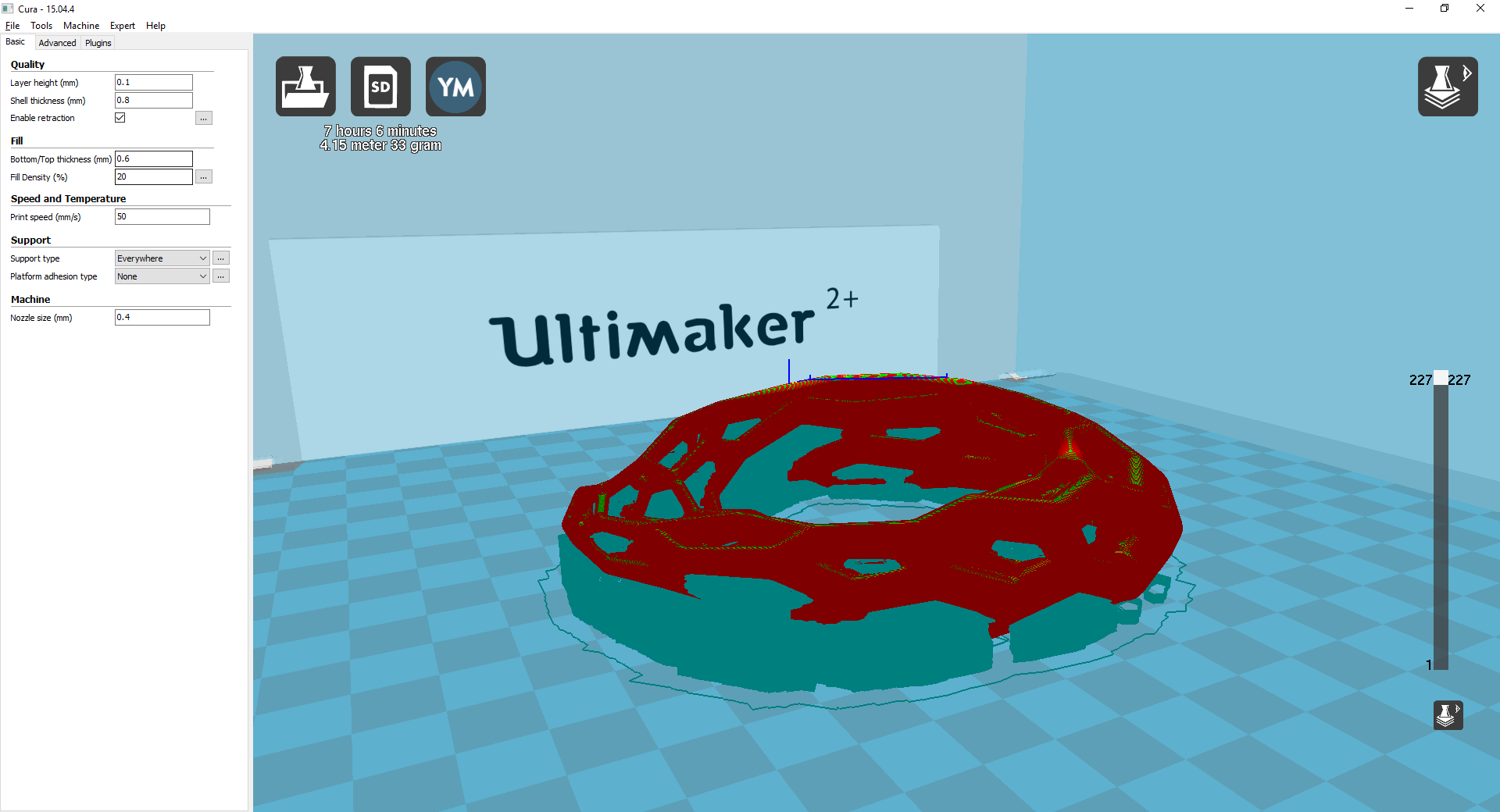
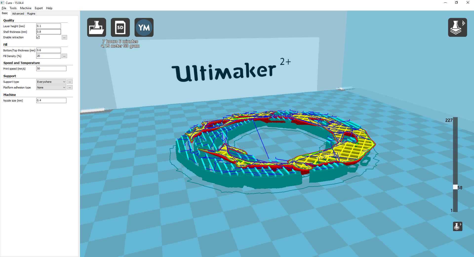
Cura
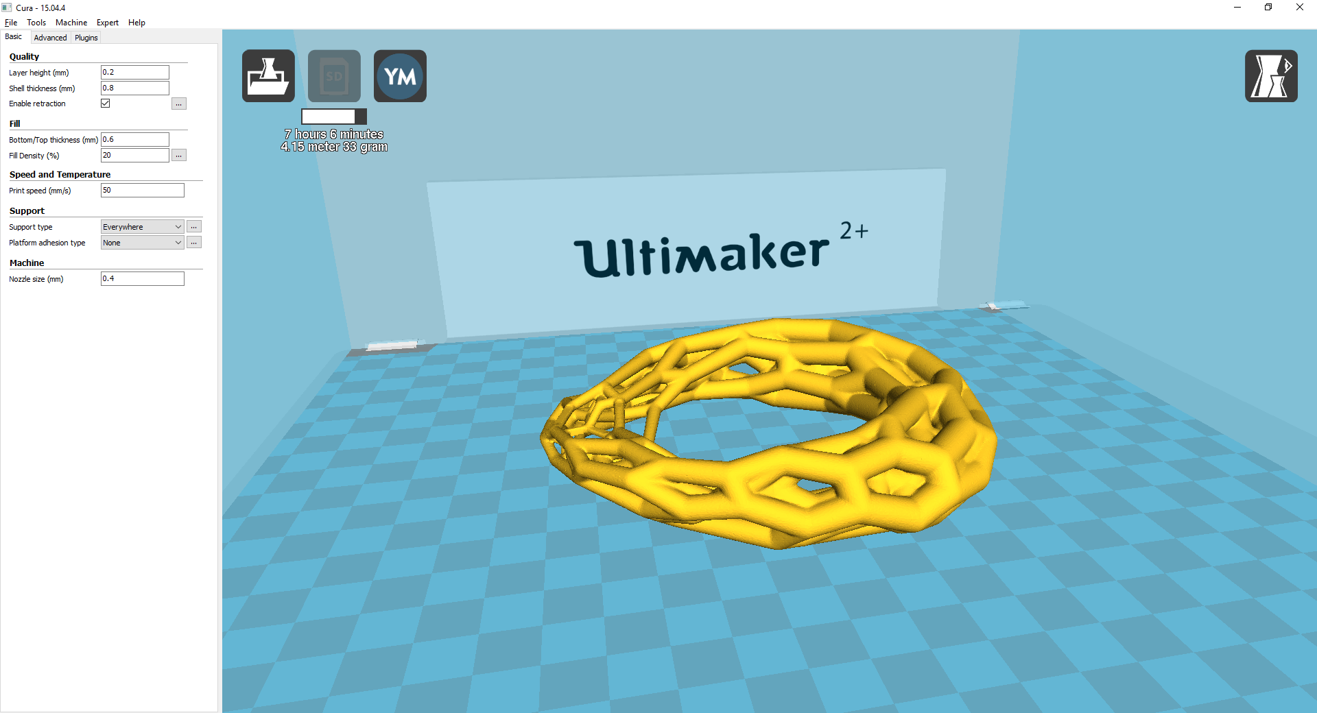
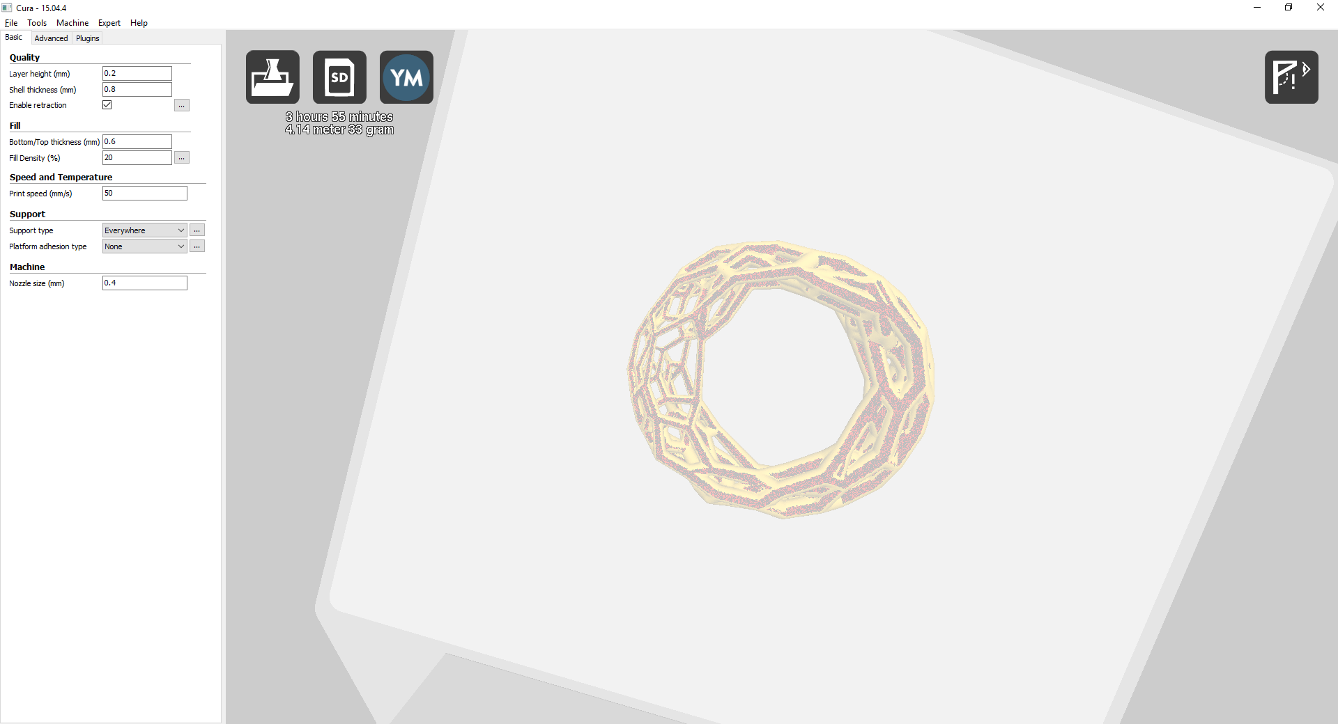
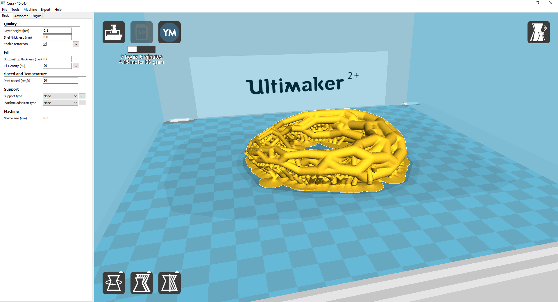
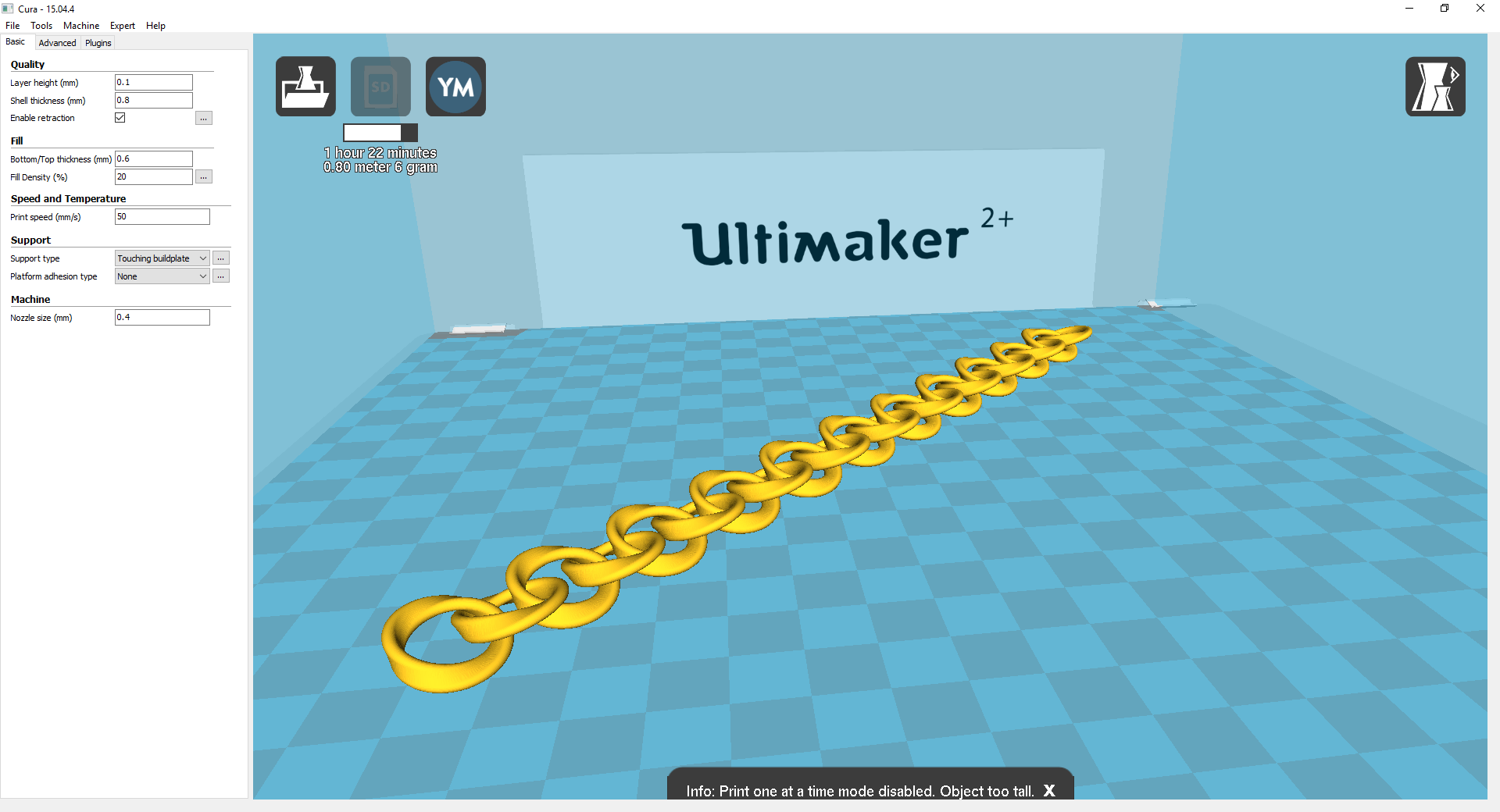
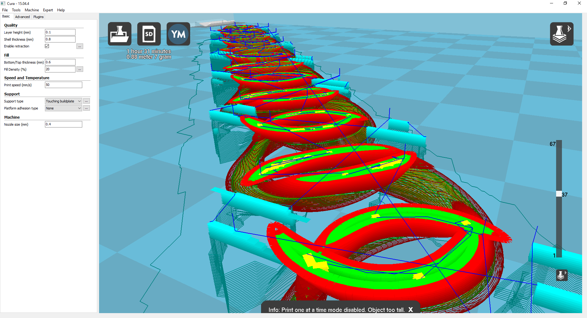
Today I've picked up the print result of the Voronoi-like Möbius strip. I quite liked it and was a good support test, every bit came out nicely, and there's not too much overhang.
Tomorrow I'll hopefully will pick up a couple of prints I left today with Meshmixer's support structure and a test print.
Update, I did not collect both prints today. I left both Ultimakers printing but the spool on the one that was printing the test Neil mentioned in the class was tangled itself and it stopped printing like at one cm high. Had a class in the morning and the printer was bussy so I put the printing again after lunch. It was going well when I left, hope to get it right tomorrow or I'll be late!
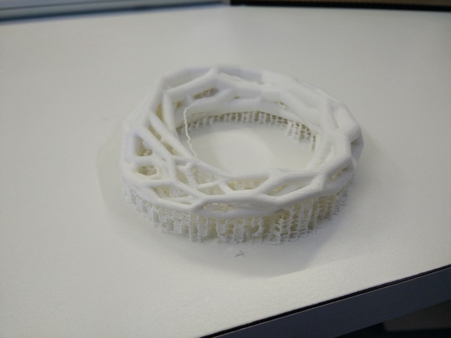
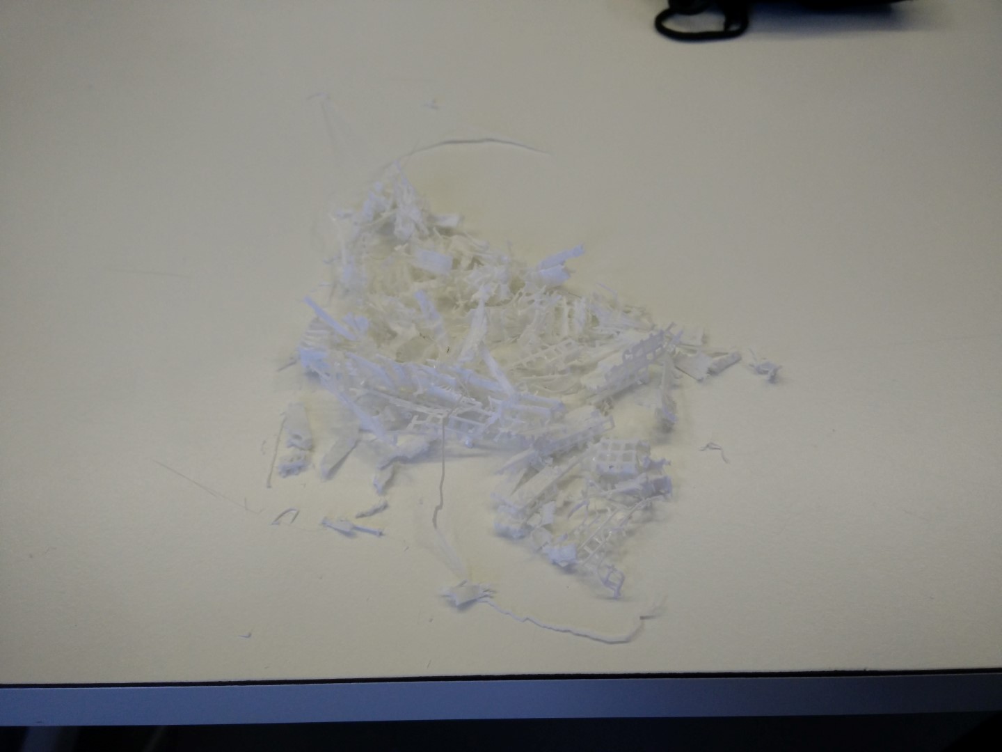
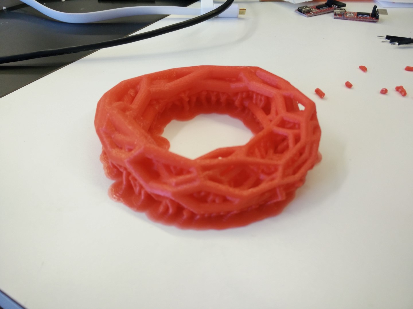
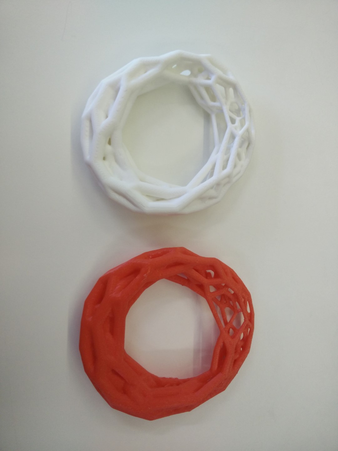
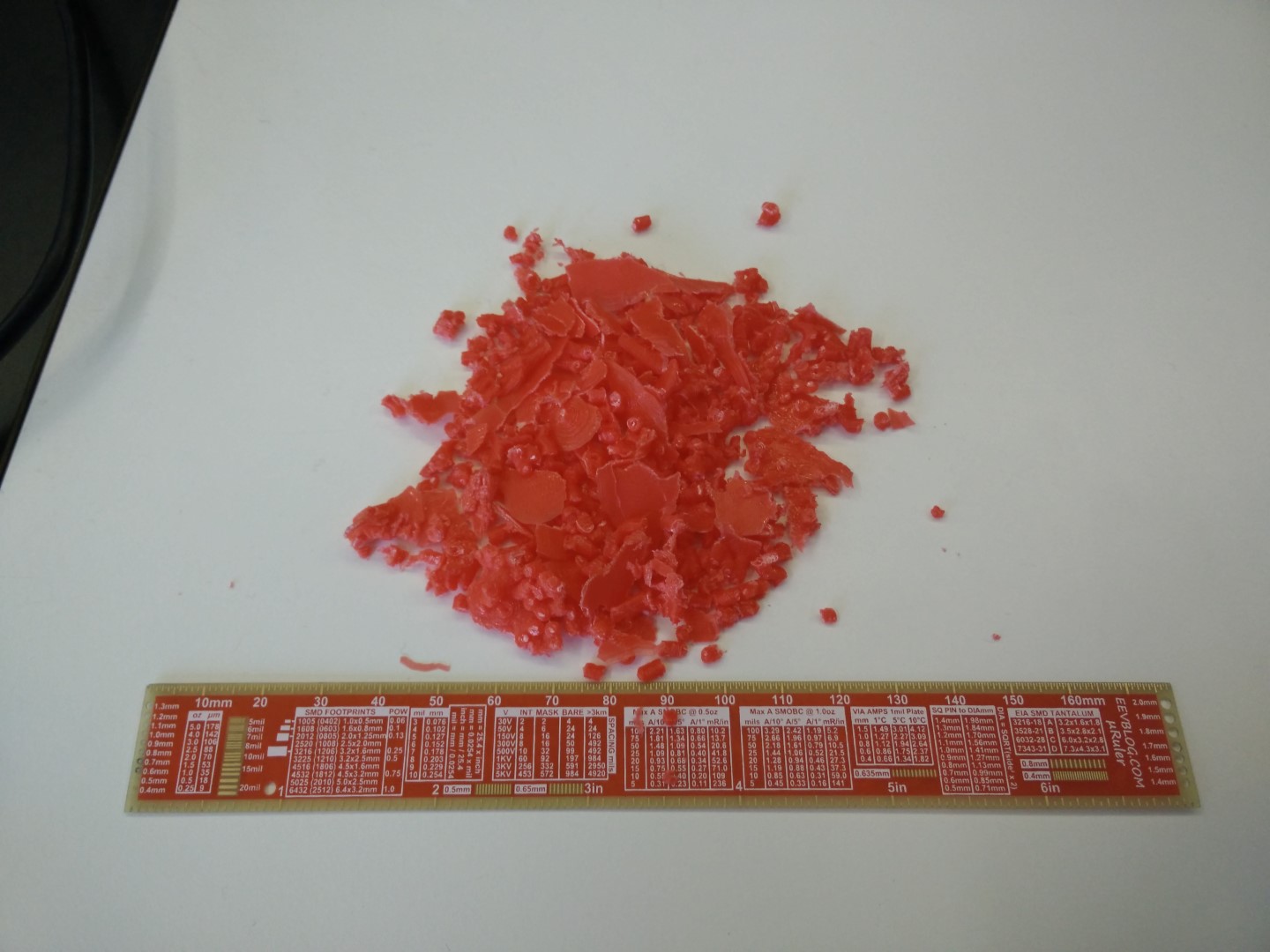
As for the other part, the Voromobius with Meshmixer's support was fine. So started to remove support before class. I had to quit because the kids arrived. It is hard to remove, and more with a geometry like this. I keep removing support on the afternoon and had to left like 10%-15% of the support material because I need more tools and time (was using pliers and a small flat screwdriver). The feel is a little better that with Cura's support, the overhang is almost none and you just get white points on contact points, that I believe could work better with a cutter.
Printer's design rules
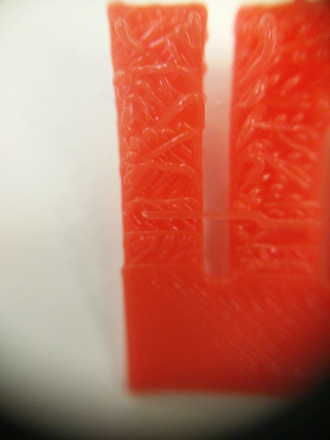
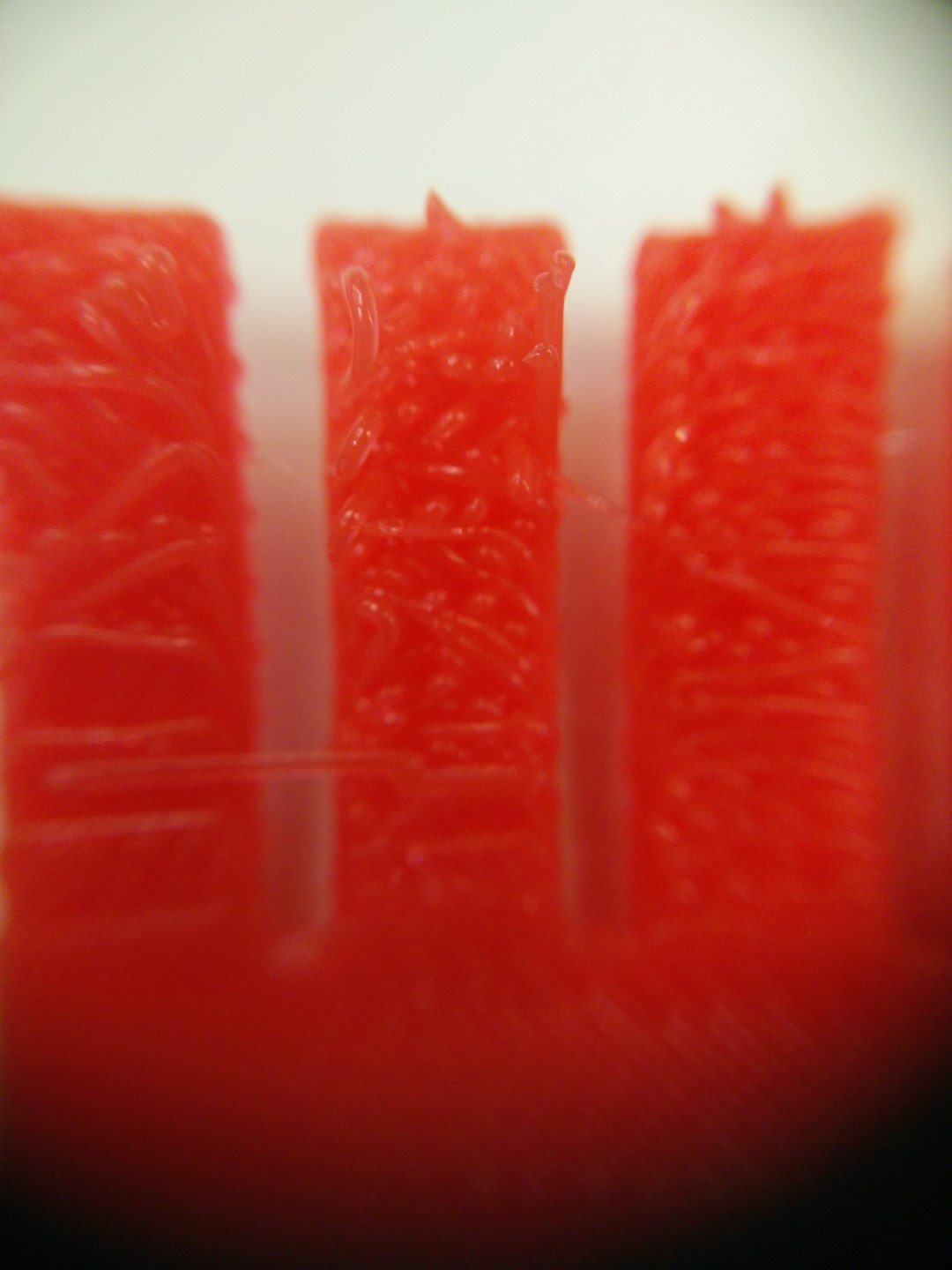
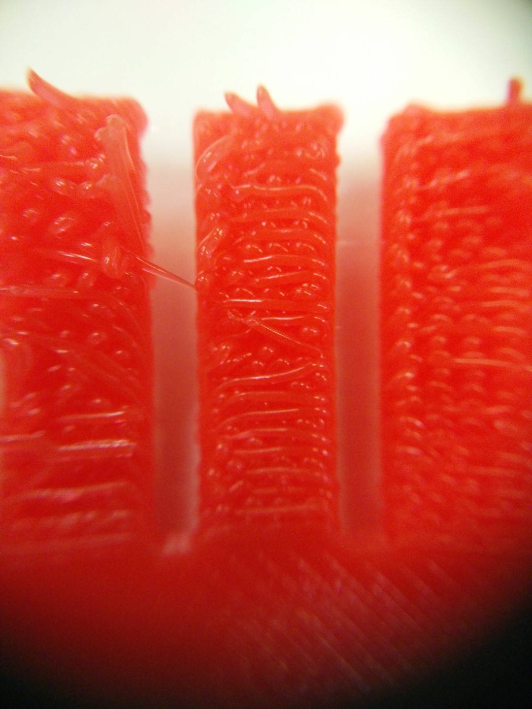
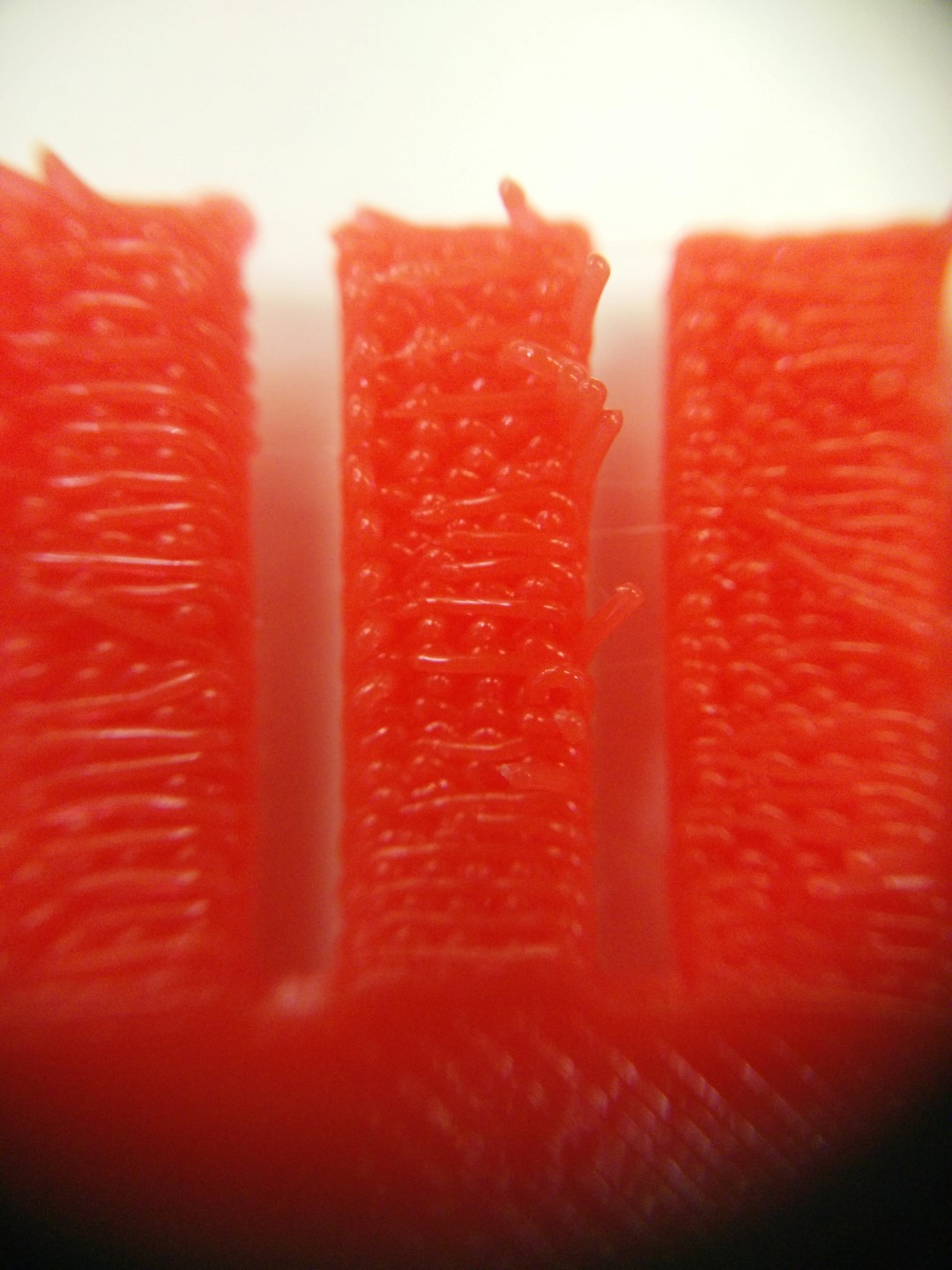
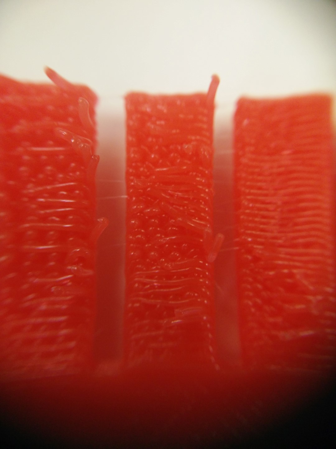
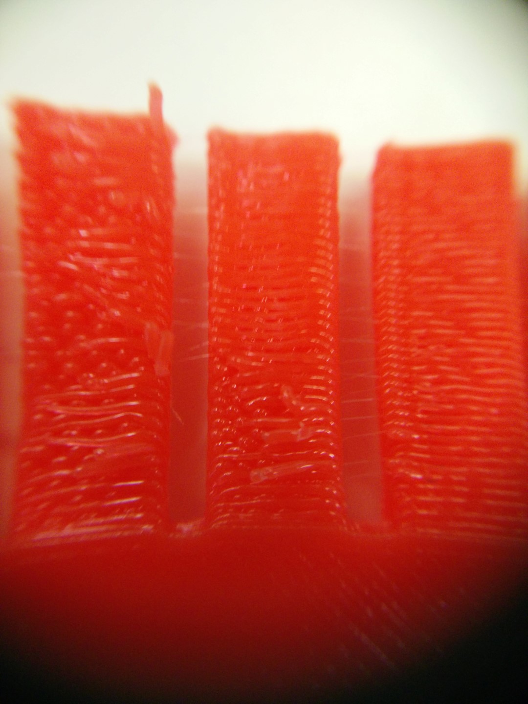
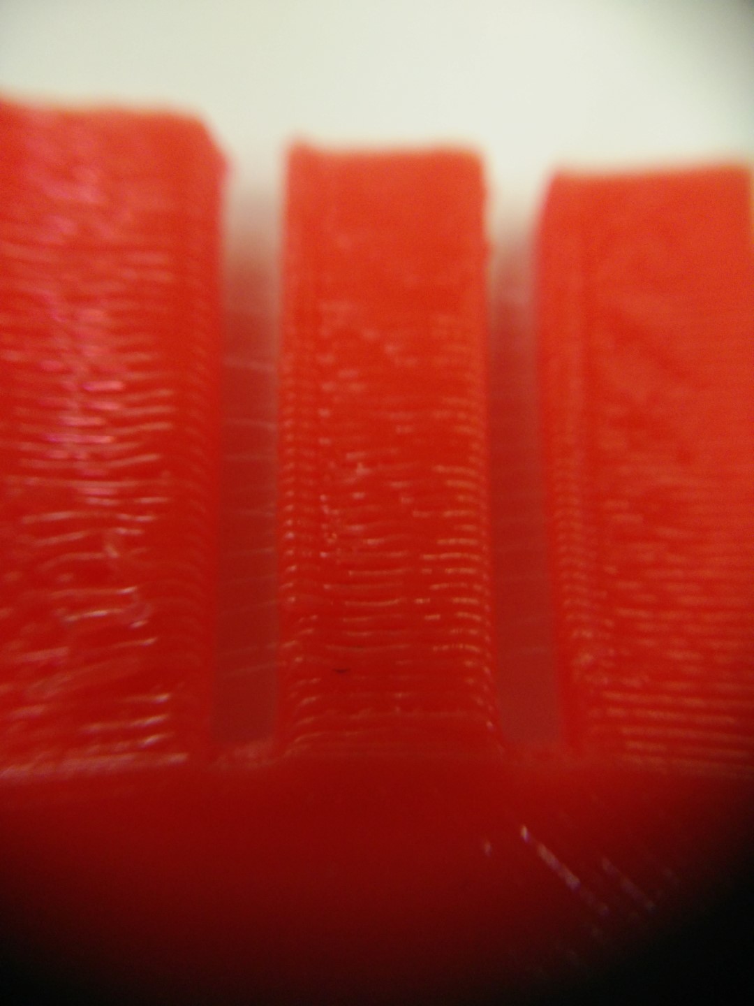
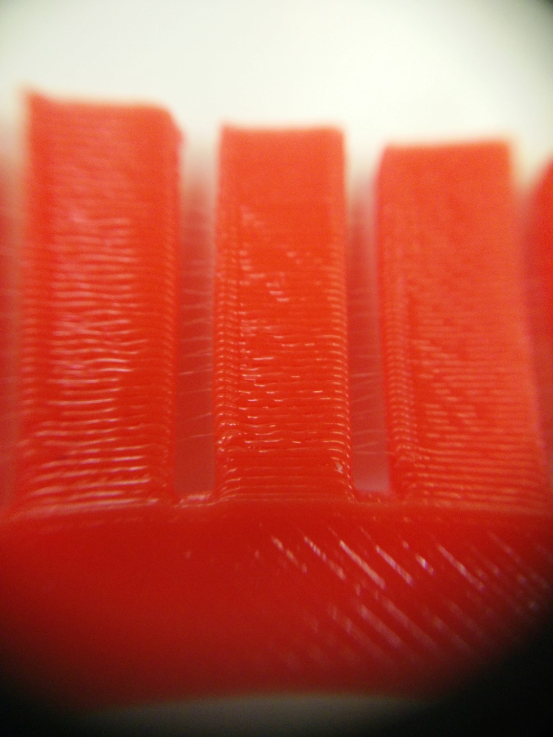
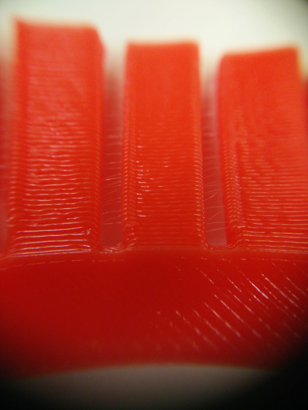
So far I have made 3 tests on design rules, hopefully, tomorrow I'll get some more from the part I left printing today. I made a temperature test, this is more a filament test and not a printer's design rule, but is something I've tried before and never did with the Ultimakers and Eumakers filament. The other test I've made was an overhang test from this Thingiverse files: Overhang test 1 and Overhang test 2
Test part 1 is an overhang test from 5º to 85º in 5º steps. The conclusion is that you get an even finish 45º and up, 35º to 45º it is still good but you can tell the difference. Anything under 30º should require support. This part has been printed with a 0.4mm nozzle, at 215ºC and a 100% infill.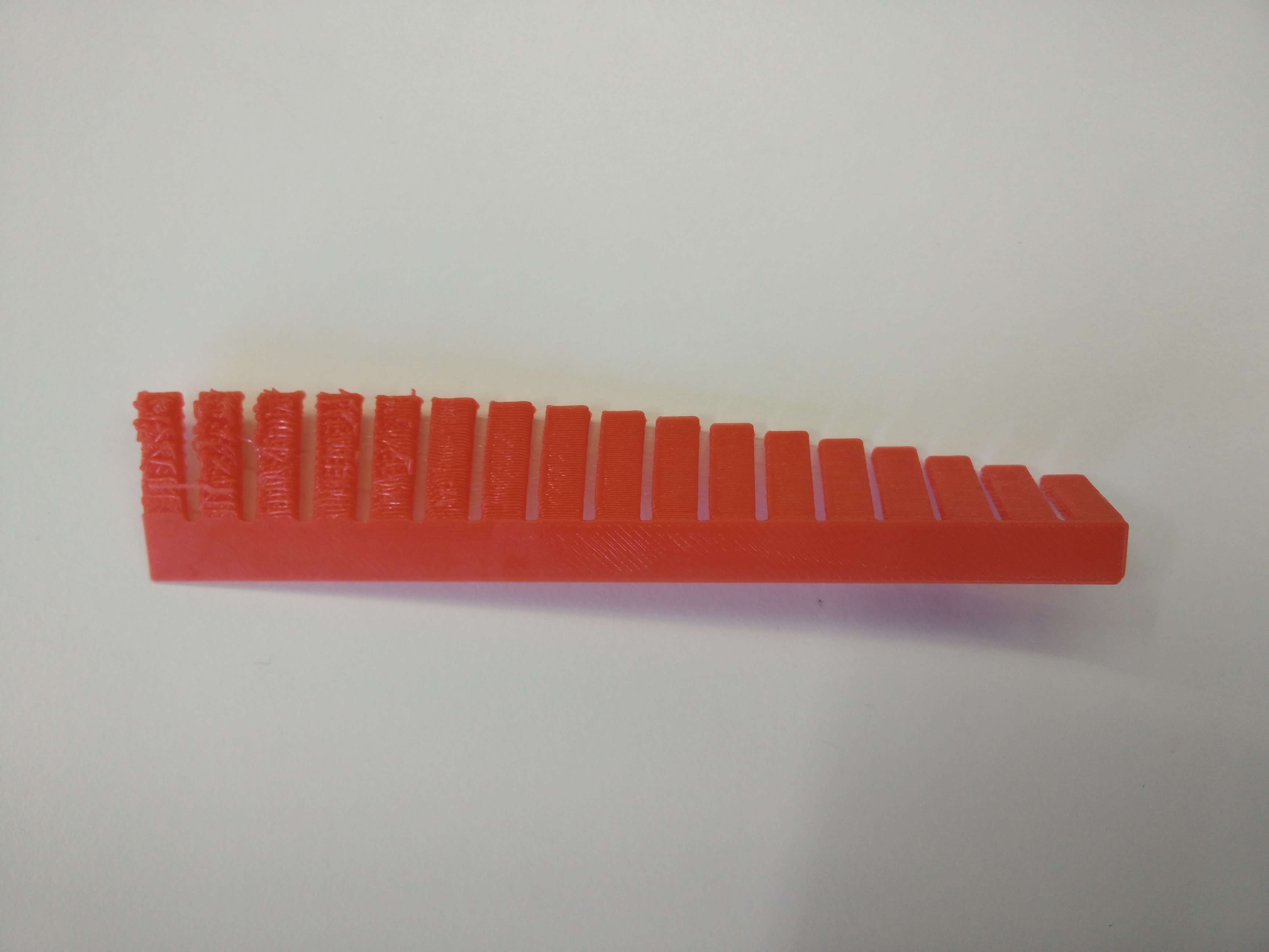
.jpg)
.jpg)