Week 15: composites
May 4 - 10
Assignment
- Design and make a 3D mold, and produce a fiber composite part in it
Object Modeling with Fusion 360
The goal for this week's composite assignment is to create a double drop longboard. A double drop long board consists of a through drop trunk mount with an additional drop where the rider stands on. This lowers the center of gravity for the rider, making it easier to learn on. I have never been much of a skateboarder, so this seemed a good way to start. In addition, the form of a double drop longboard is a rather complex one, requiring some multiple axis bends.
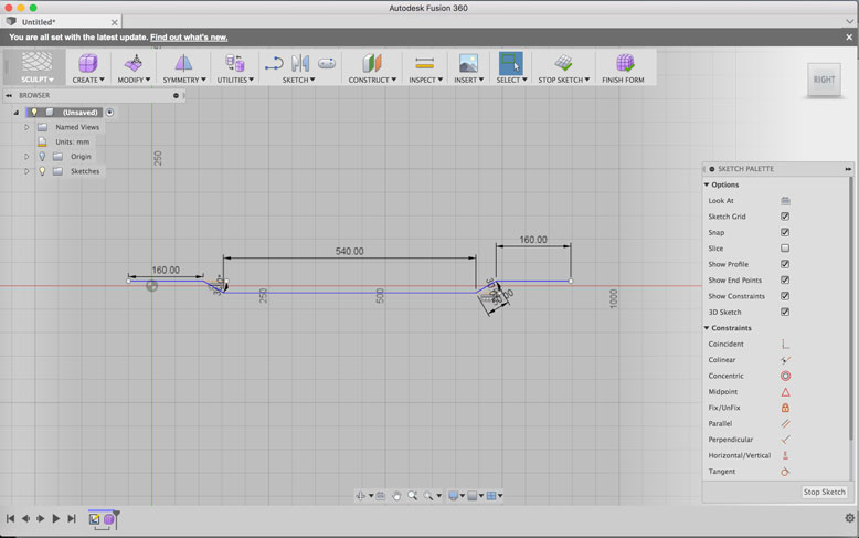
To begin the design, I used Fusion 360 and created a line sketch to draw out the side profile. As you can see, the mounting ends of the board need to be straight, while the riding portion is dropped down an inch. Luckily, Fusion 360 accepts dimensioning in both mm and inches, making the process easier than manually making the conversions.
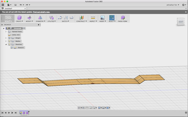
After I was happy with the side profie, including a slight bow to the riding portion, I extracted the line symmetrically (in both directions) by 5 inches, creating a 10 inch wide board.
Next, I created a rectangular sculpture mesh the size of the mold under the extracted body I did before. I then subdivide the faces in order to create larger resolution of curvature. Then, using the Pull tool in Fusion, the mesh is drawn to the closest body, which is the form I created before. After tweaking and adding some more lines, the plane took the basic shape of my premade form, including soft transitions between the different angles.
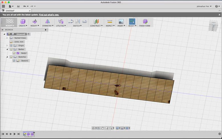
To make my life easier, I split the board horizontally in half, with the plans to mirror the form across since the board will be symmetric in this manner. An additional curve was added bilaterally in order to create a concave riding surface. This allows for better grip and ease of turning on the board. This was simply done by grabbing the ourside edges and manually moving it up by a few milimeters.
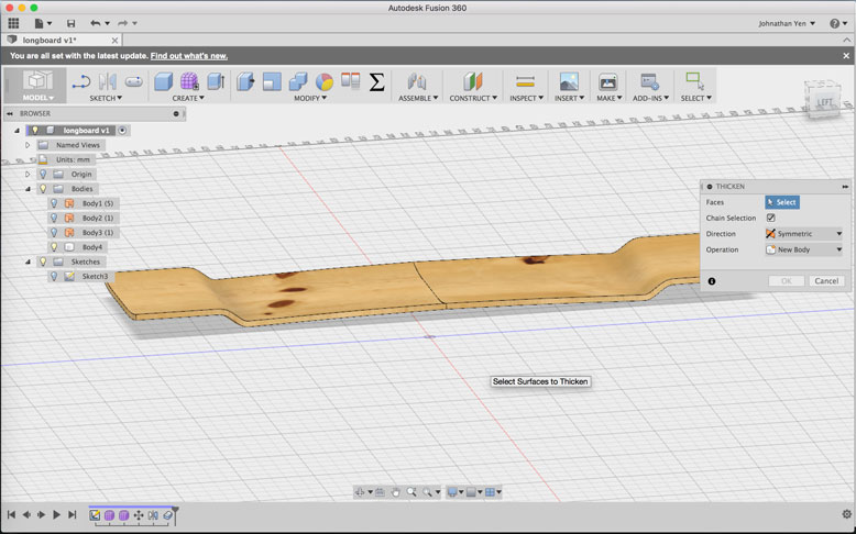
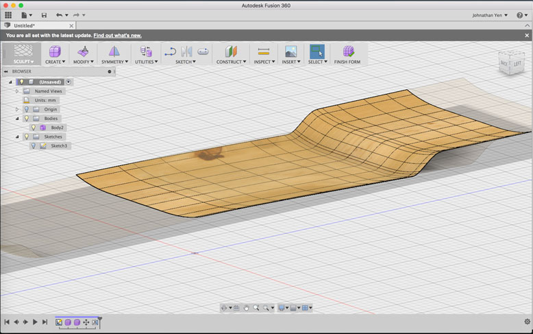
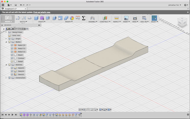
When the desired shape was accomplished, I used the Thicken tool to create a facsimile of what the board would look like. I then mirrored this body across the veritcal plane and combined the two bodies into one.
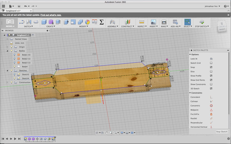
Next, I created a sketch on a construction plane moved to a higher position than the contour board. Here I sketched out the shape of my composite materials and what the topside shape would look like for the board. Once the sketch is complete, I could then extract the shape down onto the contour board using the intersect function. This removes all material that does not intersect with the extracted sketch and the contour board.
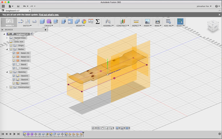
Now that I had the contour shape and a digital prototype of my final product, I set to create the mold itself. To do this, I turned to the Boundry Fill tool. This tool allows you to create a body using planes and shapes to set the boundries for planned shape. To set this up, I created multiple construction planes along the contour plane.
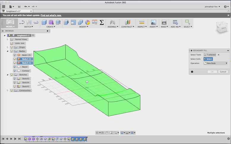
Using the tool, I selected all 5 construction planes along with the contour plane, which created this green body. I then selected the form and created the body.
Here is the final outcome of the mold, with a styrofoam texture applied to the body.
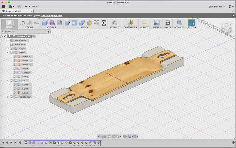
The example of the final form conformed to the mold.
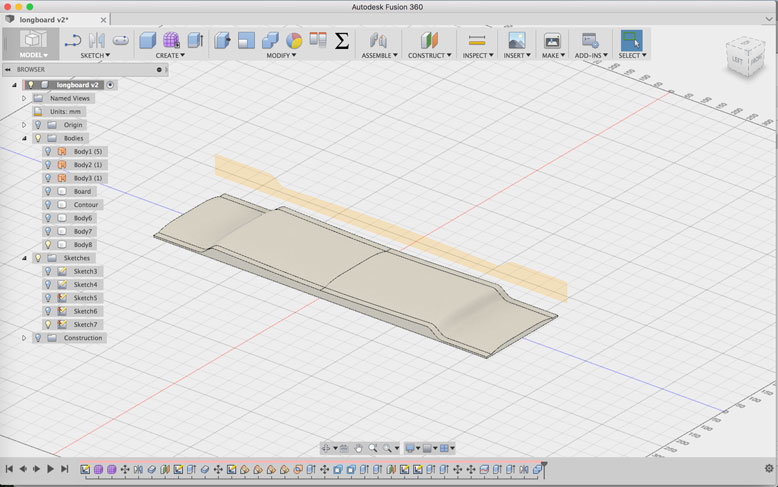
After completing the negative mold, I decided that with a vacuum form function, the result would be better with a positive form instead. I simply re-did the previous steps but using the convex side of the contour instead. This is the final mold form that I will use during milling.
Mold Machining
In order to get our elsign CNC milling machine to make 3d contour cuts, we have to process the g-code first through an archaic German CAM program called CondaCAM. It is a pretty basic process, using an imported STL and then running a rough cut and a final cut process over the model.
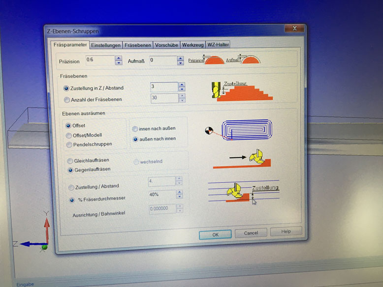
The settings for the rough cut. Note the lack of offset material under "Aufmass". This was a time saving decision that would create a slight negative outcome to the final. So in the future, I would suggest a 1mm offset for best results.
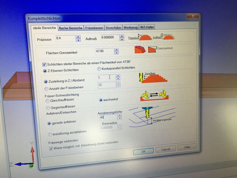
Settings for the final cut.
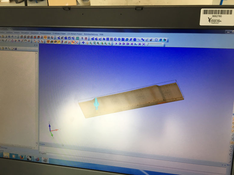
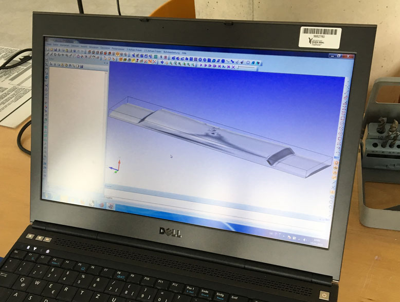
CondaCAM provides a simulation preview, which showed no collisions. So now I simply needed to output the g-code and load it onto the CAM program of our elsign CNC.
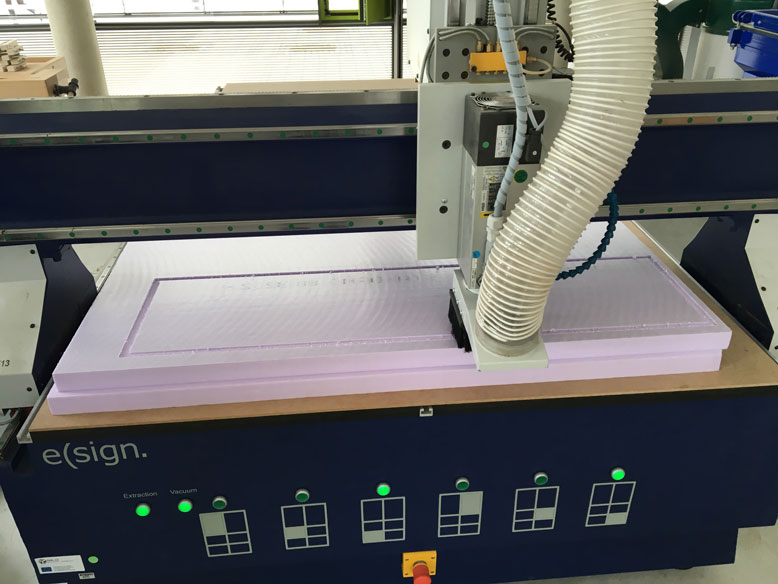
The CNC starts the cut. The initial cutting speed of 1500 resulted in a cut that would take over 14 hours. Since there were many others looking to use the CNC, I decided to manually increase the speed to 4500, which meant only 4 hours for the cut. This is possible because the foam material that was being cut is soft enough to allow it to happen. I did the speed increases incrementally while checking for the quality of the cut.
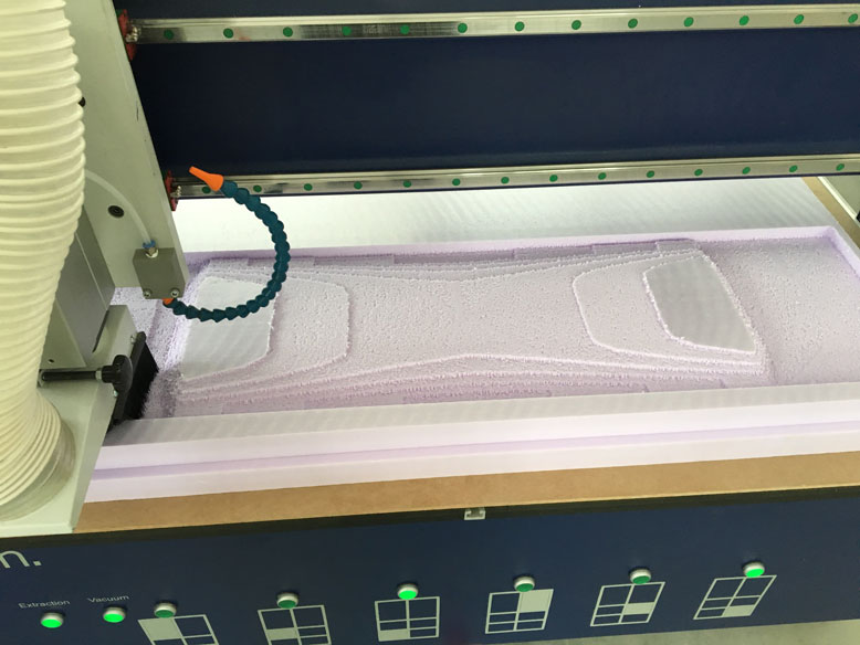
As you can see the surface quality of the cut isn't the greatest, but since this is the rough cut, this doesn't matter much.
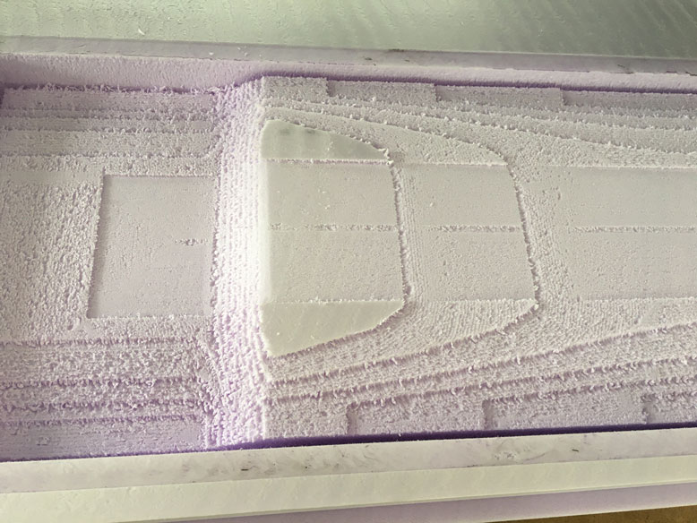
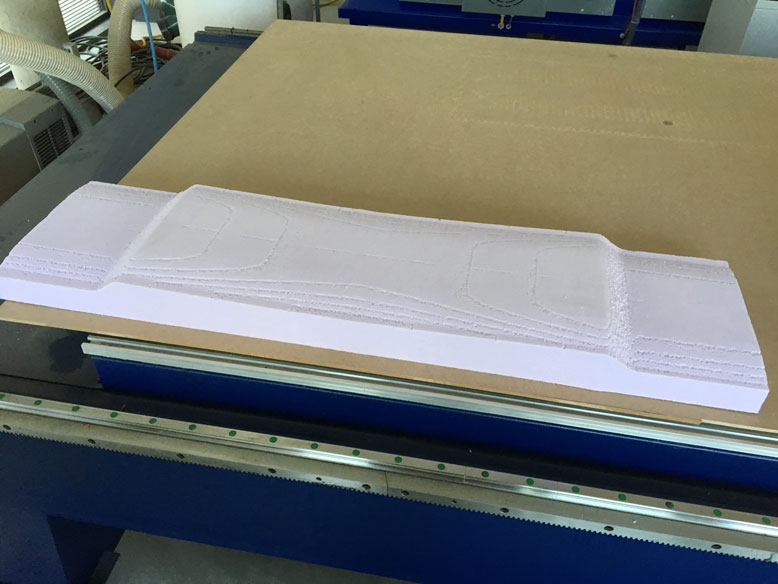
Once the rough cut finished, it moved to the finishing cut. To my surprise the cut quality decreased with lower speeds (2000), so I brought it back up to 4500, leaving a very clean cut behind. However, note that due to lack of material offset during the rough cut, there is some surface imperfections left over where too much material was removed during the rough cut. This could be solved by running the rough cut slowly, or by making a 1mm offset during the rough cut. Since the bit is capable of cutting at fast speeds, and time is important, I would suggest the latter method for such large sweeping shape applications. For smaller, more detailed cuts, the former would serve the better method.
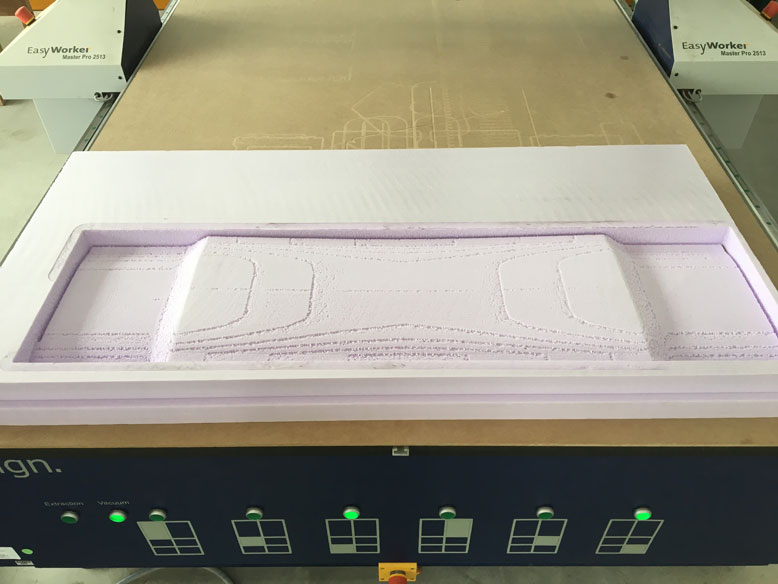
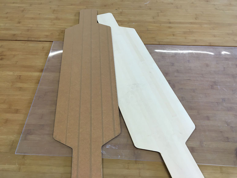
Here is the final mold after the CNC finished. Not perfect, but good enough for the purpose it is needed for.
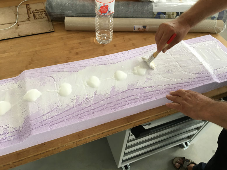
To protect the foam from the resin, a coat of glue is placed over the mold.
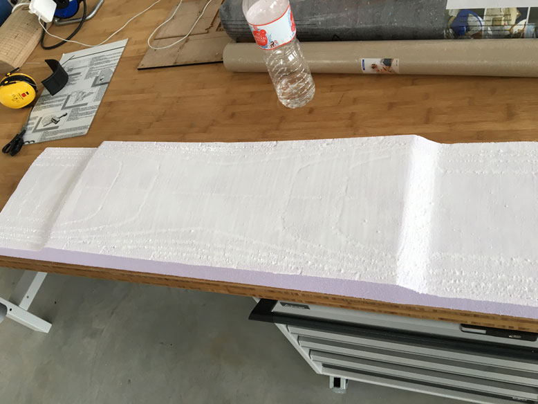
The glue is evenly applied over the entire surface.
Here it is, all dried and ready for the composites.
Composites
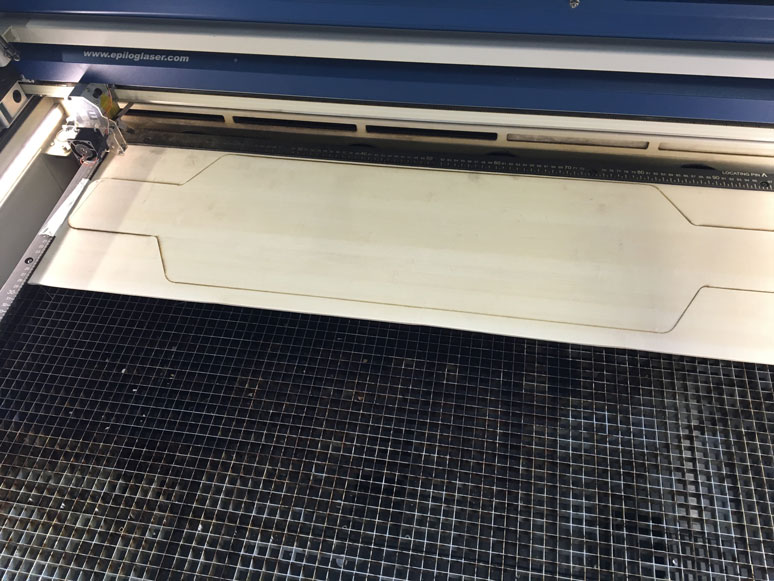
The material I'm using for the composites are thin sheets of bamboo. Based on the rigidity that I needed, I decided to go with four layers. To cut the material to the shape that I wanted, I turned to the laser cutter. It was simple to cut it with a setting of 20 Speed/90 Power/30 Frequency.
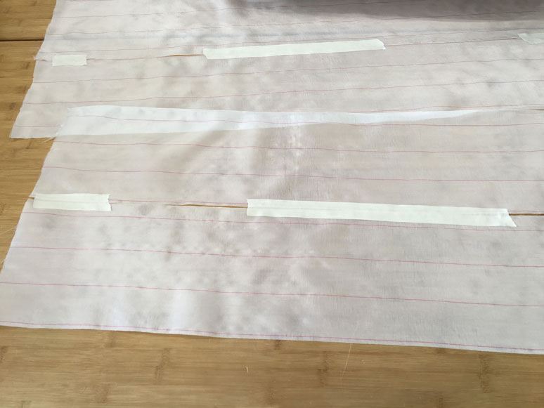
For the fiber, we had some thin fiberglass mesh on hand. However, they were a bit too thin for the entire board, so I simply just taped them together. Since the major stress would be going lengthwise, this seam won't cause much of a problem, as long as I stagger the seam on the different layers. I also cut these strips with the laser cutter using the setting of 60 Speed/80 Power/30 Frequency.
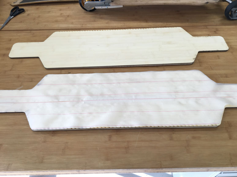
Stacked together, the pieces all aligned very well.
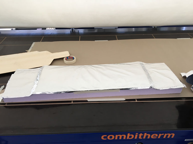
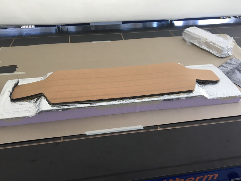
I then prepared the mold on the Combitherm. I covered the mold with a layer of aluminum foil to prevent any sticking of the resin.
Next, by the suggestion of Karsten, I covered the outer surfaces with a layer of tape. He had said that the resin caused big headaches when it got onto the outside surfaces.
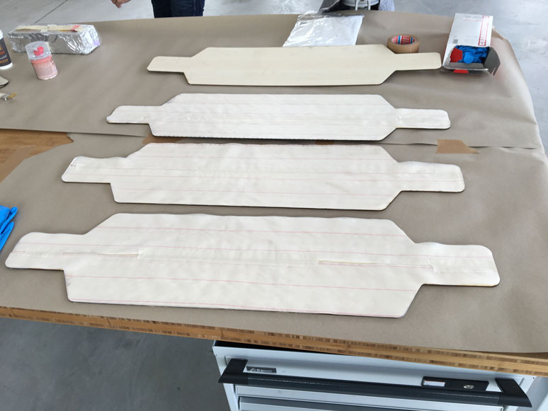
I laid out all four layers and prepared the resin.
Because the resin sets rather quickly. It says about ten minutes of working time, and thirty minutes to set. So I had to quickly mix the resin and applied it evenly on each layer. It was a bit difficult since the fiber layers were split, it was hard to keep them totally aligned. However, I got it mostly done and stacked the layers on the mold.
I then placed it in the Combitherm and applied the vacuum.
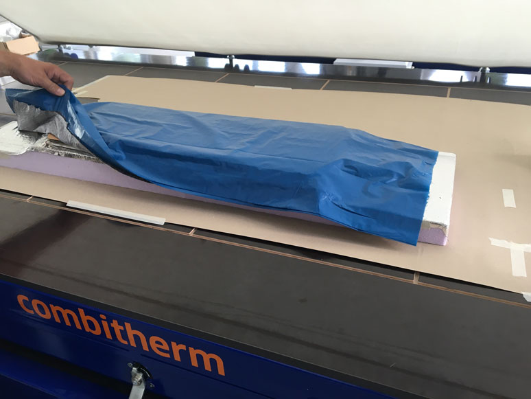
After about an hour or so, I felt it was safe enough to open. As you can see I applied a layer of felt to soak up the excess resin and a layer of plastic to prevent damage to the Combitherm membrane.
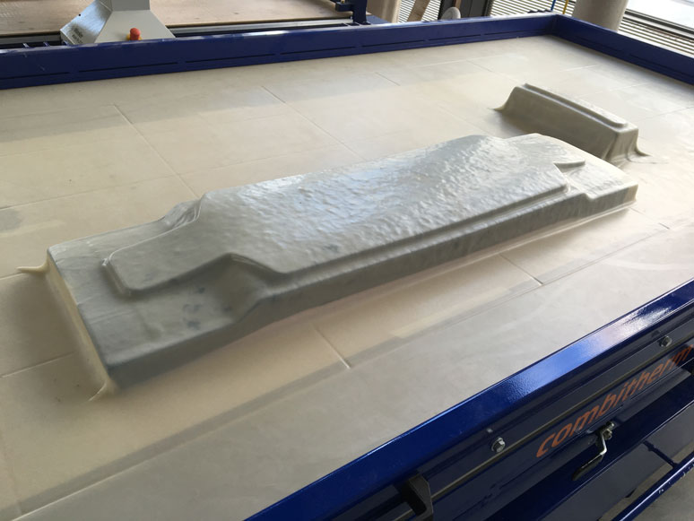
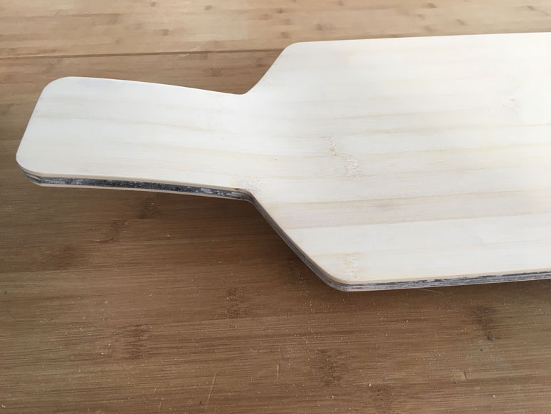
The result turned our relatively well. As you can see, the drops for the ends did not come out perfectly as I suspect the radius was a bit tight for this material. It may have been possible with more layers of thinner ply bamboo. However, for this first try, it went very well.
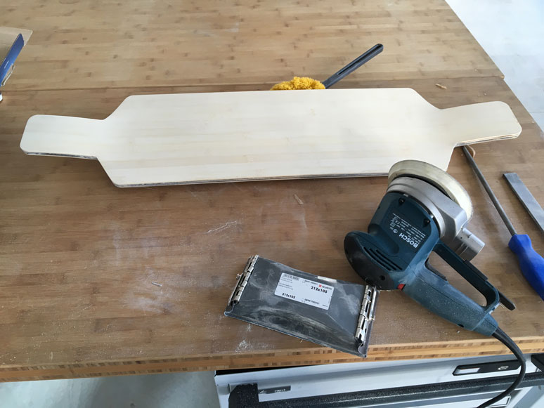
It took a bit of sanding from this orbital sander to get the resin off the edges.
However, I am pretty happy with the end result. The main body has multiple complex curves which gives the board very high rigidity. The board is very robust.