Final Project Concept
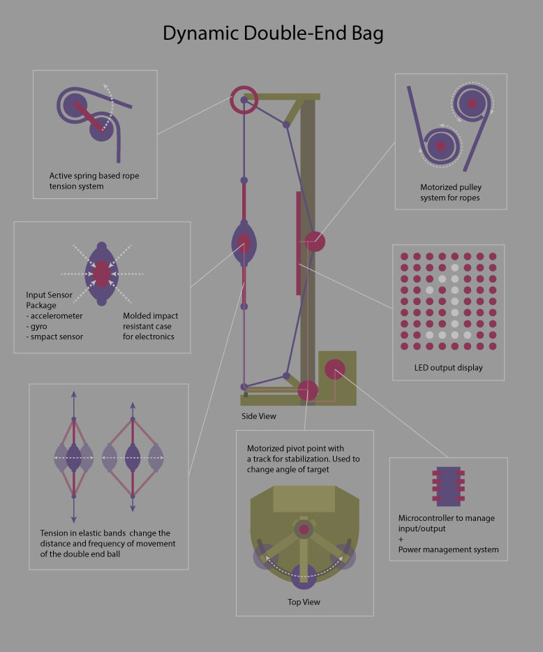 Something big, something interactive, something fun.
Final Project Functions
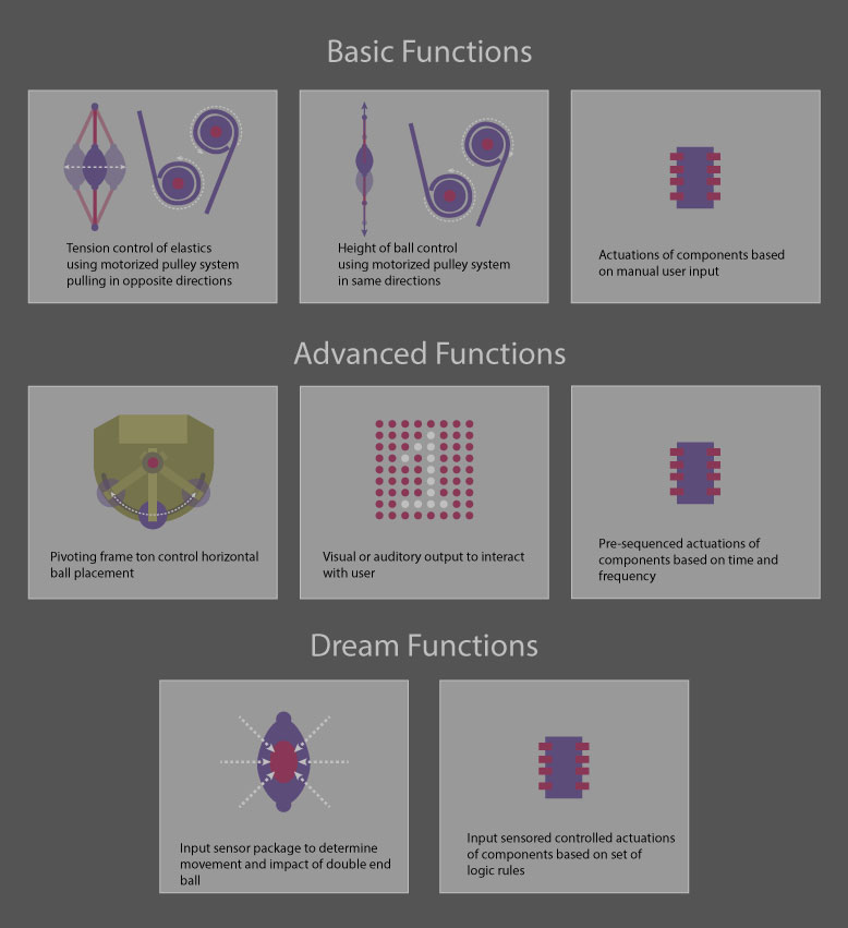 The level of functionality will be based on time and capablity.
Final Project Change
While the previous project was interesting to me and provided plenty of opportunities for challenge, I decided to switch it over to something a bit more practical. In our lab, one of the projects that we wanted to do, was a proper enclosure setup for our most used 3D printers, the Ultimaker 2s. We've always had a bit of trouble printing ABS on them due to warping, and we wanted to install some sort of exhaust system. So it was very interesting to me to do something that provided me the same challenges, while fullfilling a need for our lab.
Project Phase Index:
Phase 1: A Test
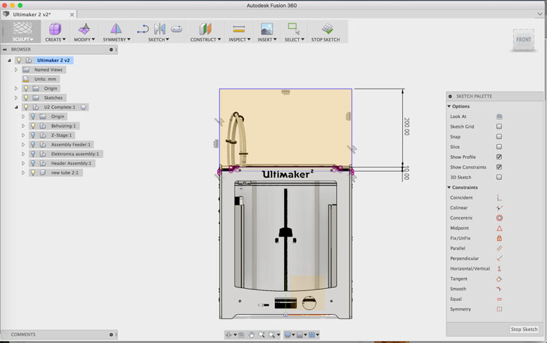
To get a better understanding of Fusion 360, I set out a side project to create top side enclosure for the Ultimaker 2. This is useful to help keep temperatures consistent for prints. This is especially useful for higher temperature materials such as ABS. To make this enclosure, I found a fully modeled Ultimaker 2 and imported it into fusion. This way I could project the dimensions of the machine on to my sketch so that it would fit seamlessly.
Part of the practice is to work parametrically and have a clean workflow. This kind of workflow is unique to history driven parametric design, and requires a bit of practice to have the proper discipline to keep each function enclosed in itself. In other words, if an adjustment is to be made, edit and modify the previous function, rather than applying an additional function on top of the design history.
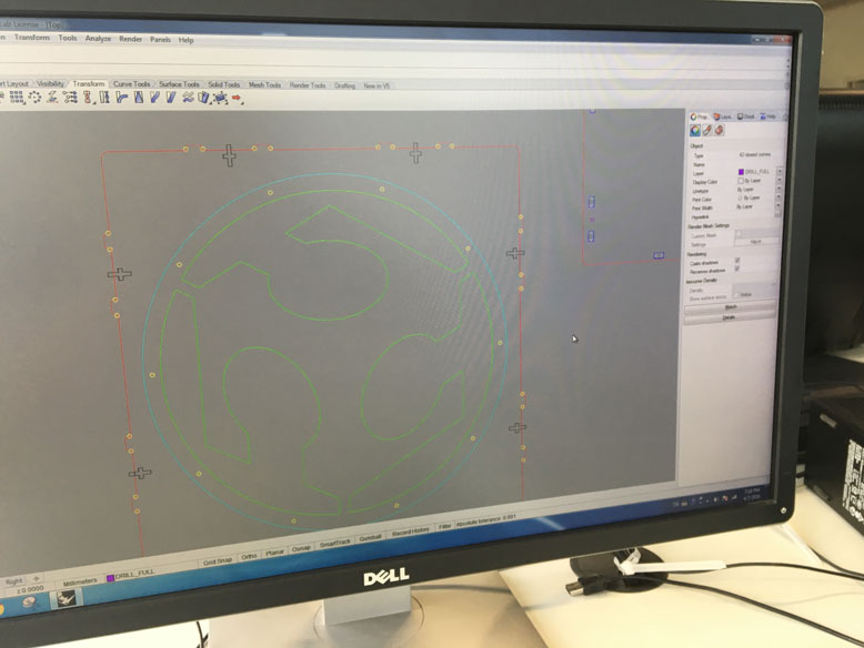
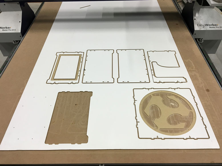
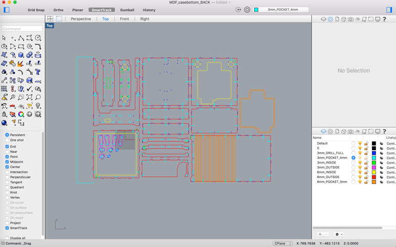
My goal is to use the CNC to cut the shapes out instead of the laser cutter. This is due to the ability of the CNC to do 2.5D cuts, thereby creating slot pockets instead of going all the way through. This creates a more aesthetic outer surface, akin to the Ultimaker itself. To process the vector lines to be understood by our elsign CNC, I run the DXF file through Rhino3D. Here, I seperate my cuts into seperate colored layers. These include, full drill, 4mm drill, 4mm pocket, inside cut, and outside cut.
These layers are recognized by the CAM software, so each step can be done step by step. As long as the material doesn't move and the machine doesn't lose the X/Y/Z zeroing, then everything should be perfectly aligned.
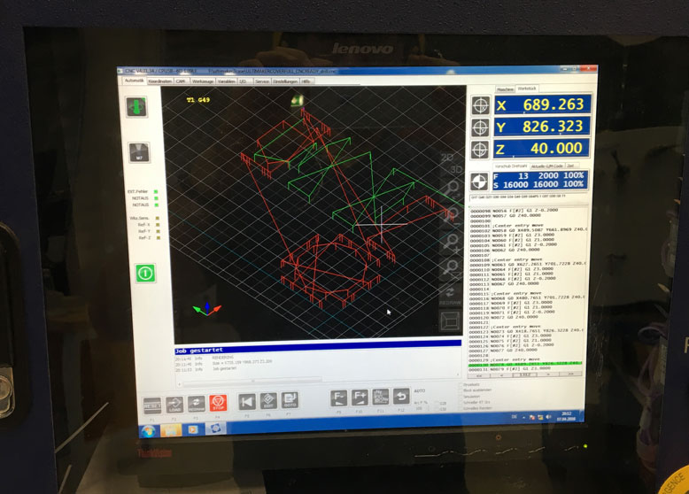
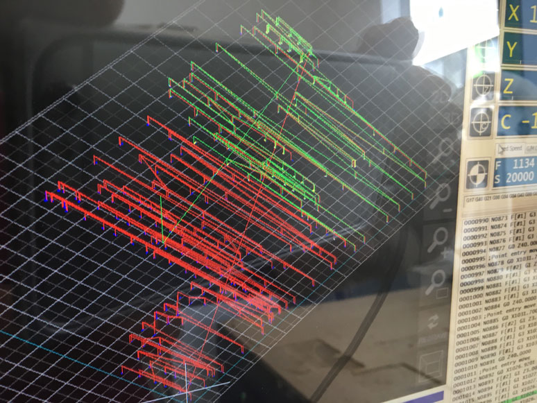
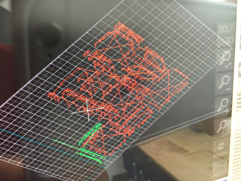
The CAM software shows a 3D simulated path, so you can double check if this is the cut you wish to perform, and its location.
Step 1: 4mm drill with 3mm bit to create dogbones for pocketed slot holes.
Step 2: Full drill with 3mm but for other slotted dogbones
Step 3: 4mm pocket for hidden slot holes
Step 4: 3mm pocket for future attached 3mm acrylic windows
Step 5: Inside cuts using 6mm bit
Step 6: Outside cuts using 6mm bit
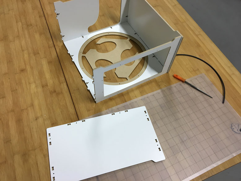
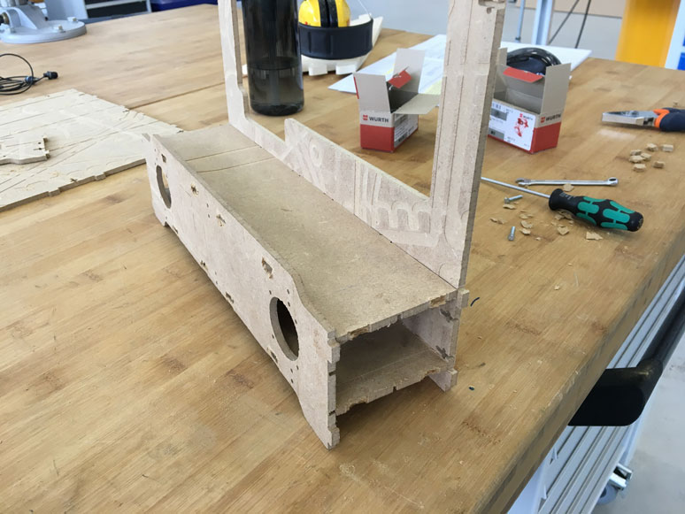
Pieces being assembled. They fit pretty snuggly using press fit, but there are slots and holes available for bolts and nuts.
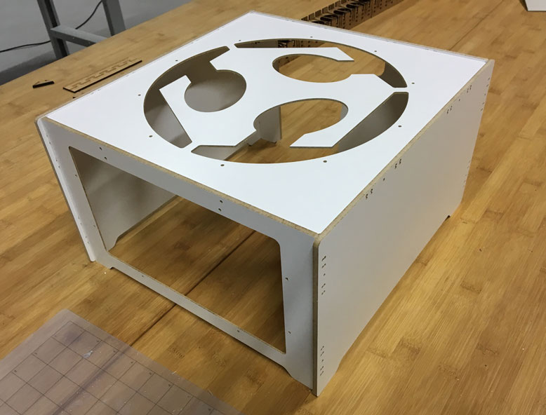
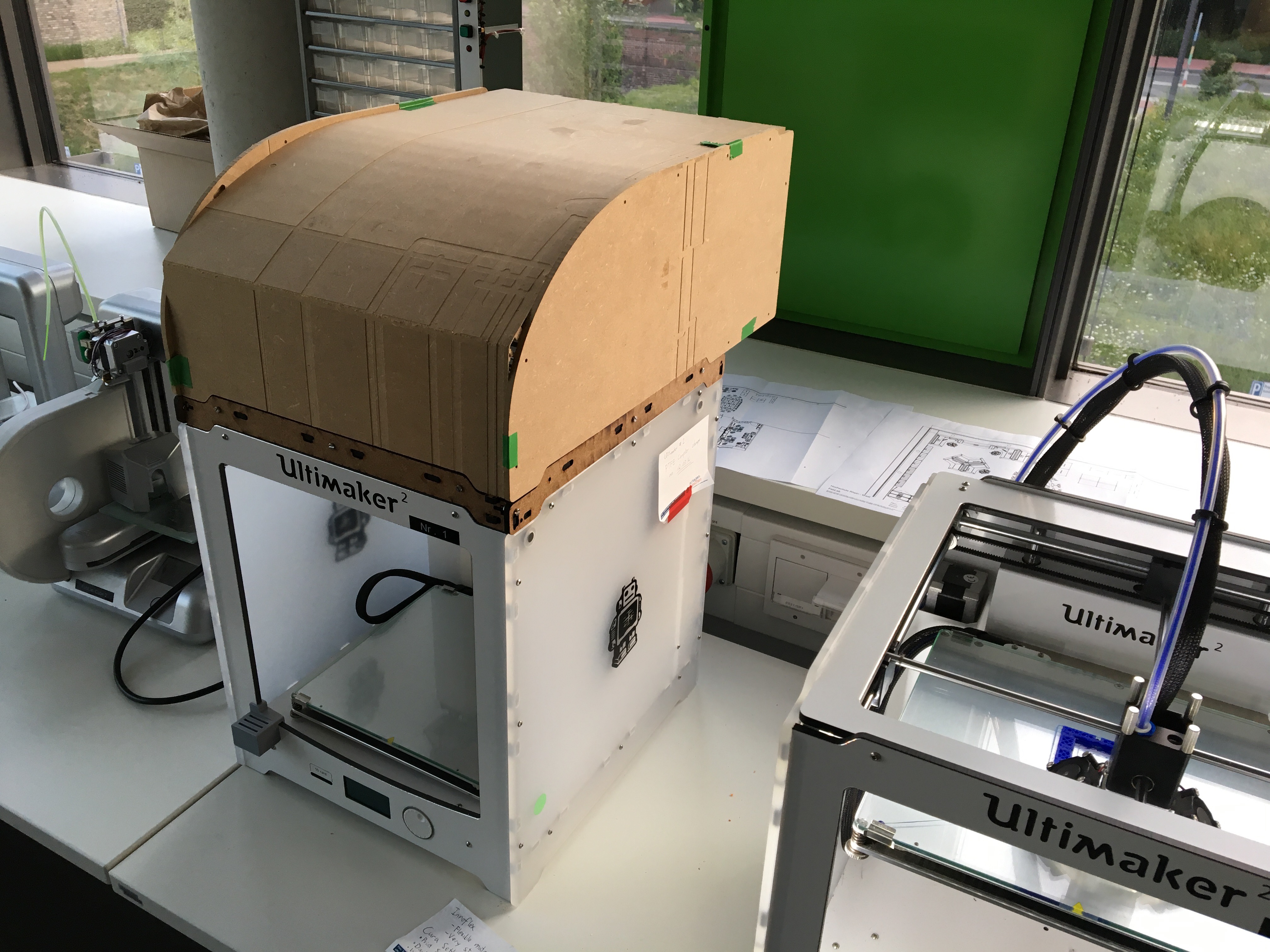
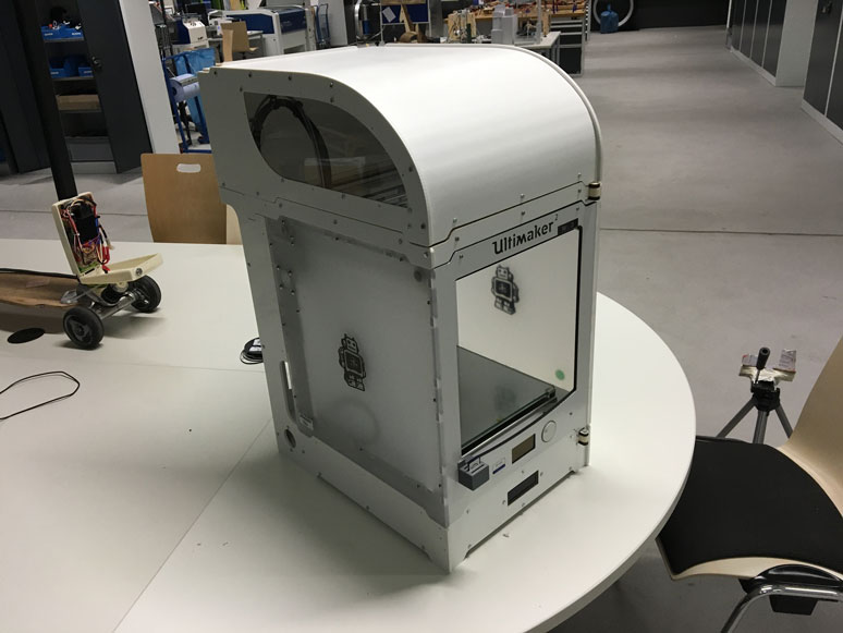
Finished putting it together, minus acrylic windows.
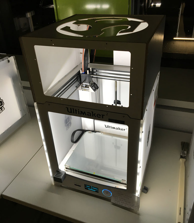
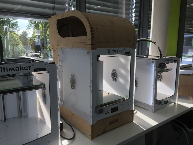
Test fit on the Ultimaker, fits very well. A few modifications would be nice, but good enough for a very first prototype of the process.
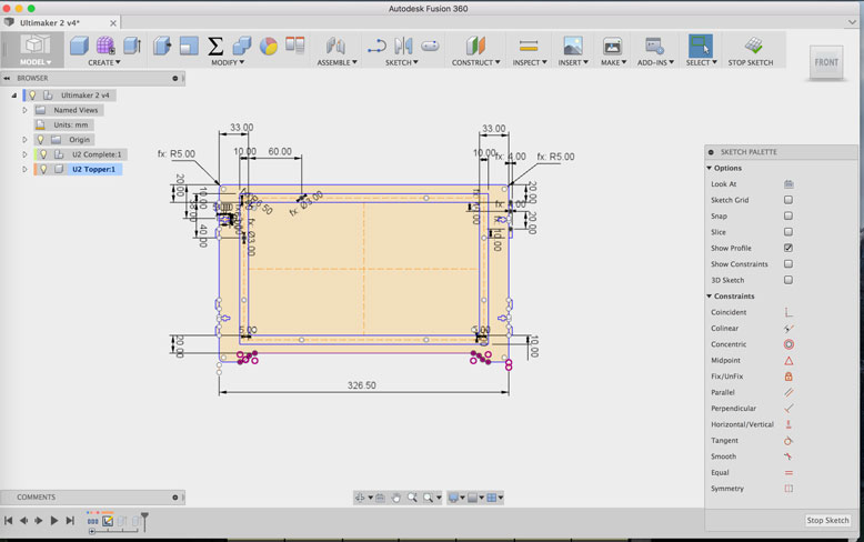
Phase 2: Bigger Plans
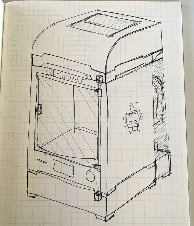
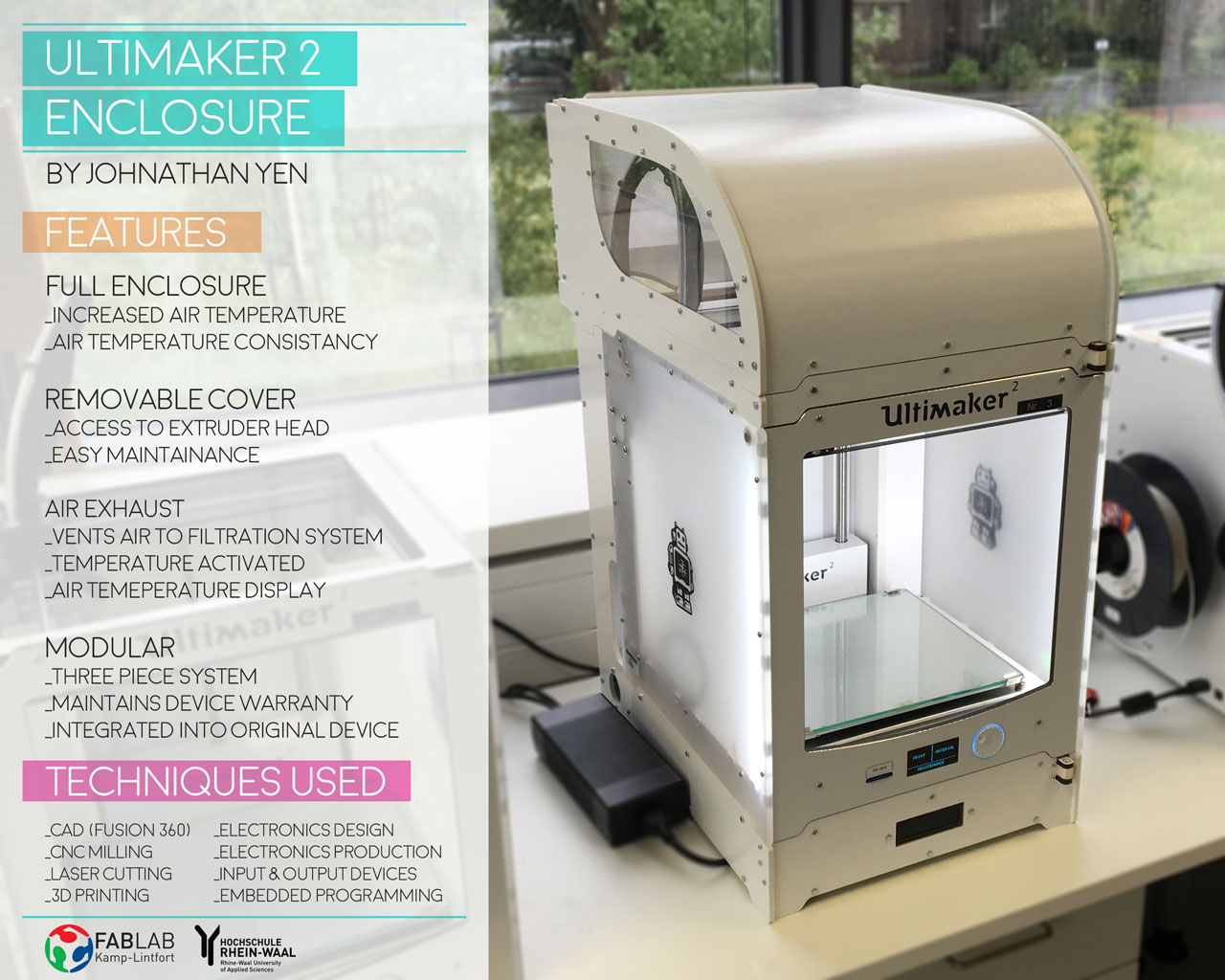
Using what I learned, I drew up a design for the final project, which would include sensor electronic functions. The goal is to create a 3 component enclosure for the Ultimaker 2, that makes no modifications to the machine itself. This preserves the warranty of the machine, and is completely and easily removable. In addition, the design of the enclosure should match as closely the visual design of the machine, in order to not make it seem tacked on. The enclosure should contain and modulate the temperature of the inside, and provide an exhaust to an attached filter if neccessary.
The three components: Top, Crown, Bottom. The Top is a simple casing to trap the heat. It should be easily removable to have access to the extruder head and filament for maintainance. The Crown is the topside holder of the hinge for the door. It is seperated from the top, as if they were one piece, the door would fall out every time you removed it to do maintainance. It also contains a temperature sensor to sense when the machine is running or not. The bottom is a base that holds the bottom hinge of the door and also includes electronics to read the temperature sensor. Based on these readings, it will modulate fans for the exhaust system as neccessary.
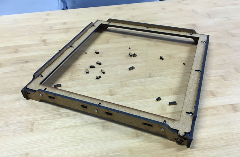
To test the design of the crown, I used the laser cutter to quickly and cheaply make some test prototypes for fitting.
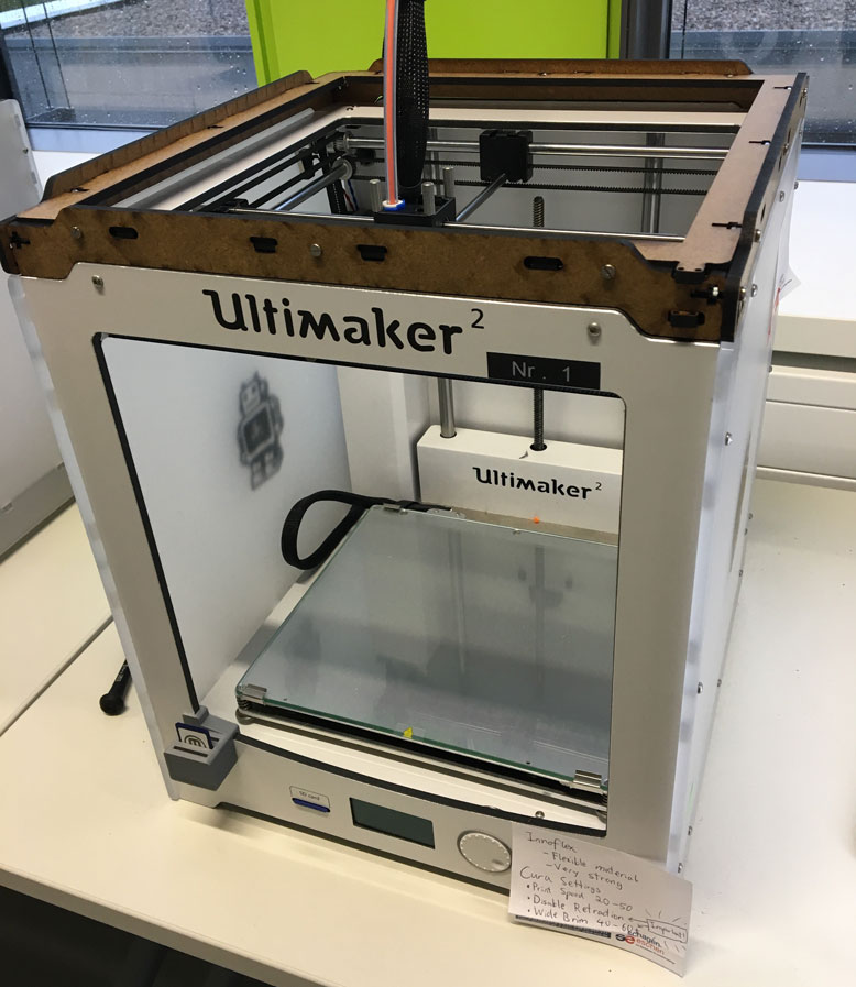
Here it is on an Ultimaker. The holder for the hinge still needs a bit of work to make sure it is strong enough for multiple instances of use.
Phase 3: Design Time
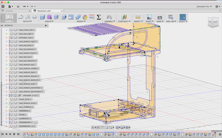
To achieve what I wanted, I delved deep into Fusion 360. I could probably fill a book with the amount of work I did to get everything just right. When you are dealing with integrating something with an object already created, it can sometimes come down to thousandths of milimeters. One limitation I ran into right away was due to working on my laptop. While it has a good processer and RAM for days, the video card is rather substandard. I found that if I extruded too many complex shapes from my sketches, the program would crawl to a snails pace. So in order to have a decent working environment, I had to avoid most extruded bodies. This meant I had to work in sketches only. This isn't too big of a problem, since I only needed sketches to export them into the DXF files I need for the CNC. However, this meant I had to mentally extrude the sketches to foresee what they looked like. It also meant I had to be extra careful for the placements of tabs and bolt holes. I had to keep in mind which face each sketch represented. This wouldn't be so hard, but for something of this complexity, I had to keep my mind cached with each sketch, its face, and its immediate relation to what it is connected to. Also, as with the construction of the Pixel Planter, it was important not to create impossible fittings, and still make the bolts and nuts accessible for constructions. My head exploded.
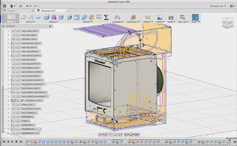
To aid with the design I was able to find a fully modeled Ultimaker 2 online from GrabCAD. This was useful, so I could build the enclosure around it. However, I faced the same problem with video rendering, as having this viewable pretty much killed my laptop. So, in order to work with it, I had to project out some basic faces and reference points. Unfortunately, I soon found out from some tests, when getting the fittings just right, micrometers will make some parts fit, and others not. The model was very well done, but some of the measurements didn't quite match up to reality. So I had to use the model as a rough guide and use calipers and measurement tools on a real Ultimaker 2 to make the proper adjustments. This process was grueling and required many tests.
Eventually I got into a groove of design. Obscure measurement numbers of spacings, lengths and widths of certain components become second nature. My mind is now filled with useless stuff which I may never forget. Better than a jingle for a shitty radio commercial, I guess. When I was happy with the direction I was going, I decided to CNC some tests, to see if there were any additional adjustments needed.
Phase 4: Prototyping Part 1
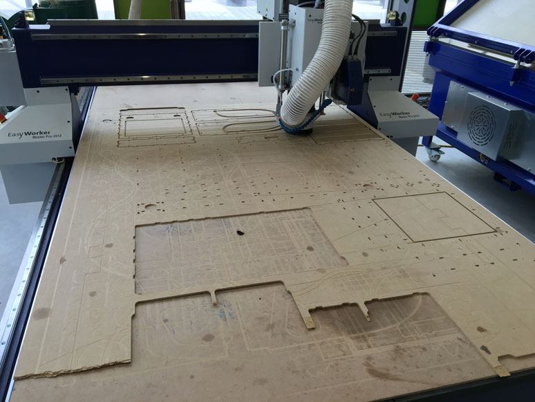
The first test I wanted to make was the top cover portion. It features a kerf cut bend in the material, so it presented an area of complexity that I wanted to make sure was perfect before I used some good material. We had some left over 5mm MDF that we had used as the trash plate for the CNC. It had been milled on both sides quite a lot, but for these tests this was a good use of this otherwise useless material.
I followed the same process as before when using the CNC. However, since this time I was cutting into MDF, rather than multiplex wood, I felt safe to push the speed a bit higher. Even so, the entire cut process would take a couple hours or more.
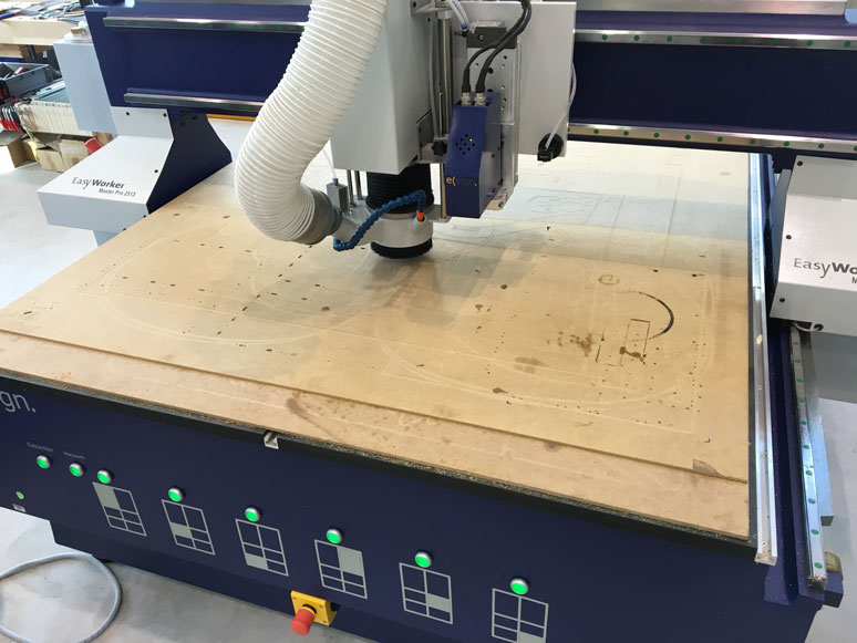
I went ahead with the cut. You'll notice the CNC may look a little different. This is due to it getting a sweet little upgrade in the last month. Included in this upgrade is an automatic lifting/lowering dust guard, laser sights, and an automatic tool changer! Sweet! This thing is a joy to use now. The only thing holding it back is its archaic CAM program. We hope to get it working with Fusion 360's CAM process soon. That would definately help with the workflow.
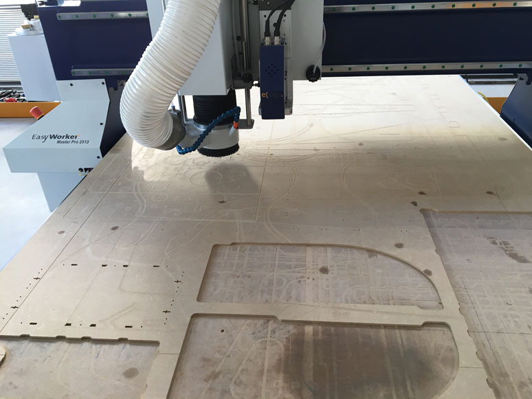
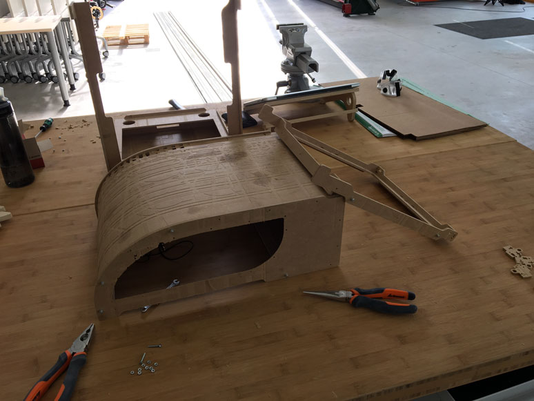
The cut went without much of a hitch. I took the oportunity to record the kerf cut portion. I remove 4mm from the 5mm sheet to allow the bend to happen. However, on certain sections of the curve where no material is removed, I create tabs and a nut holder and bolt slot. This gives the curve additional structure and helps the curve align with the side contours.
Here is the end result of the first test. You'll notice a fold on part of the curve. This happened because there was a left over mill on parallel to the curve, which meant the material went below 1mm there and caused a weak point. The final material would not have this, so I did not see it as a problem. There were some things I learned from the test:
- I went a little too fast with the 3mm bit, causing a slight jitter and unclean cuts
- The calculations for the curve on the flat end was a bit long, by about 2 mm. Adjustments would be needed to get it to fit perfectly.
- There was excess vertical height room for the bowden tube. As the top is quite large already, any space I can save vertically would help in the aesthetics
- The opening for the bowden tube was a bit small, causing slight amount of rubbing. As this would be used over a long time, any rubbing at all was a bad thing
- Use of cover prevent any good visual lines towards the print at the start when it is high up. This tends to be the most important time to check on the print, so I felt a window of some kind would be vital.
- The cover was a bit back heavy, so proper support would be needed to prevent it from flipping off the machine
Phase 4: Prototyping Part 2
So I went back to designing. This time I made the adjustments needed and worked on the lower base portion. I extened the sides on the back to raise up in order to mate with the crown. This would create a bit of tension to prevent the crown from flipping forward when holding the door. It also provided an additional shelf for the top cover to rest on. I had to take care to create openings large enough for a hand to reach behind the machine to access the On/Off switch on the left, and on the right for the filament guide. I also removed a notch from the back to allow easier access to change and handle the filament. It was not easy to think of all possible use cases and issues one would run into with the enclosure. So, it took a lot of thought and mental run throughs to try to capture every little aspect. for example, I made a little runner notch on the lower back portion as well to allow the power and USB cable to run in a neutral position away from the machine. For the crown I had to include a slot, so I could split it to fit around the bowden tube. I would often just stand in front of the Ultimaker 2 and stare at it for hours just thinking through usage cases.
Anyways back to milling. For this test, I wanted to construct the entire enclosure including the top, crown, and bottom. I still had extra 5mm MDF from before with just enough space to mill everything I needed. Good use of material, I suppose!
The second run of the top cover yielded a more sleeker look with the addition of two side windows. Overall, I really liked the way it turned out. This test also allowed me to test out some of bolt fittings. I found that we were rather low on 16mm length 3mm bolts, so I had to made do with 20mm length ones until I got some more. That's why the connectors have a bit of Frankestein's monster look to them.
A good reason for these tests is to find some small mistakes. Notice the misalignment here on the back end. This was due to a mental error of which face a sketch represented for a horizontal piece. I went up instead of going down. There were a few errors like this, but that's the purpose of this test. I noted all the adjustments I would need in a notebook and continued on. One mistake included an error due to viewing the entire enclosure in sketches. For the tabs, I used a 4mm pocket into the 5mm material. This allows 4mm of connection between the pieces, but still maintains a clean surface on the outside face. I had used the same technique on an inside facing surface that required connections from both sides. Since I had milled from one dirrection, the tab hole that should have been facing the other way was blocked by the 1mm left over material. I face palmed and imagined that I had a grave design error. However, I quickly realised that I could just simply mill these connection pockets all the way through. This was not an outward facing surface, so it did not need this beauty treatment, and by milling the pocket all the way through I could slot a piece into that side no problem. Crisis adverted.
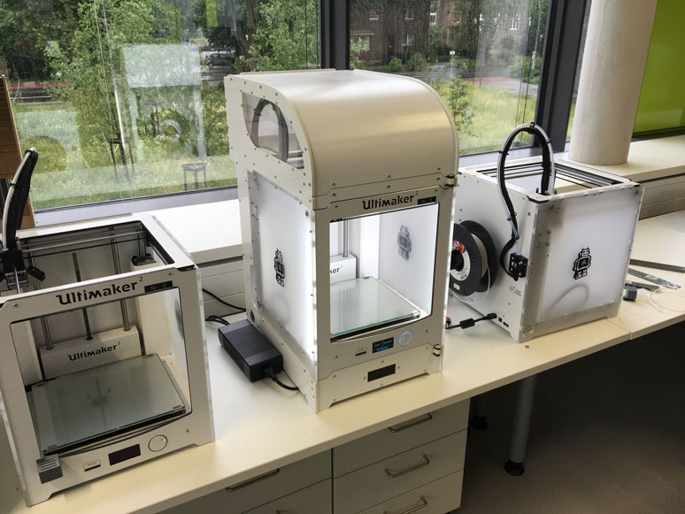
I did a test fit with an Ultimaker 2. It fit like a glove. No surprise, because it was designed that way.
Phase 5: Final Mill
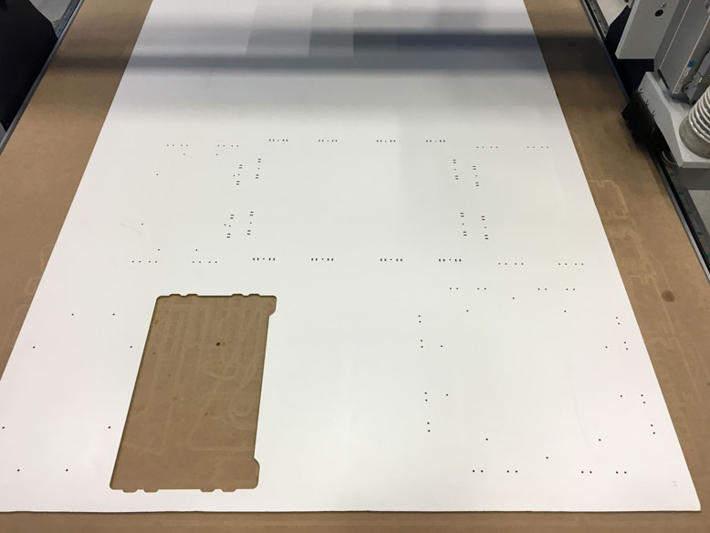
Once I made all the adjustments that I had noted in my design, I set about making the final mill. This was a bit of a tense moment, as the material I planned to use was a bit limited. I did not have too much room for error. So I did triple, quadruple, checks in my design, logic checks, and general prayers to the CNC gods. The first step for the final mill was to seperate my sketches out into 3 different plates as I planned to use 3 different materials. To follow the design cues of the Ultimaker 2, the sides would be milled with this sexy white 5mm ABS plastic. The middle portions milled with a white veneered 5mm MDF. The windows would be milled from a clear plastic. I chose to mill the windows instead of using the laser cutter, because I wanted to use a pocket cut so it would mate seamlessly with the side plate of the top cover.
So once I had the pieces separated, I had to go through the layer process that I documented in the previous CNC cut. Additionally, I made sure to close all my lines using the Join command in Rhinoceros 3D. The DXF files that Fusion 360 outputs are nice, but sometimes have weird anomalies that are caused by points or overlapping lines. It's not a big deal for Rhino 3D, but will cause major headaches for the elsign CAM software.
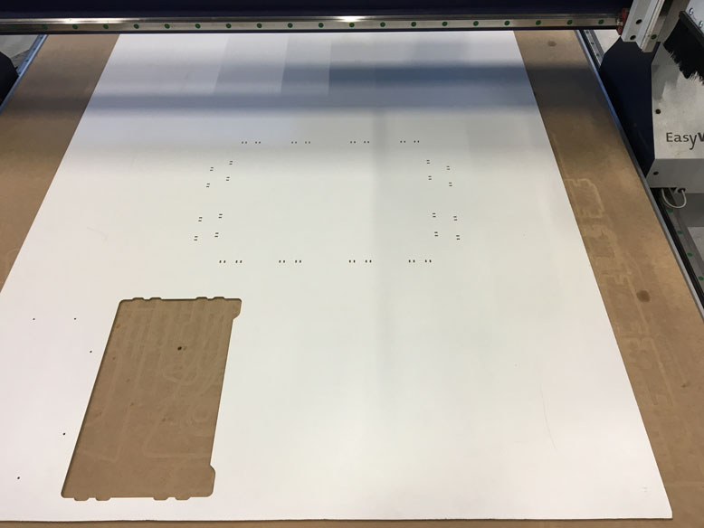
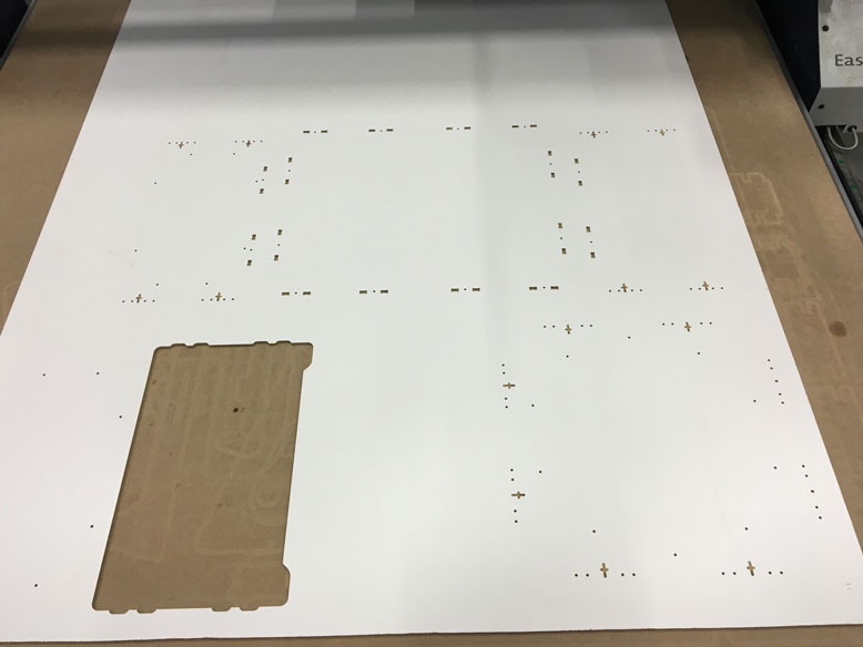
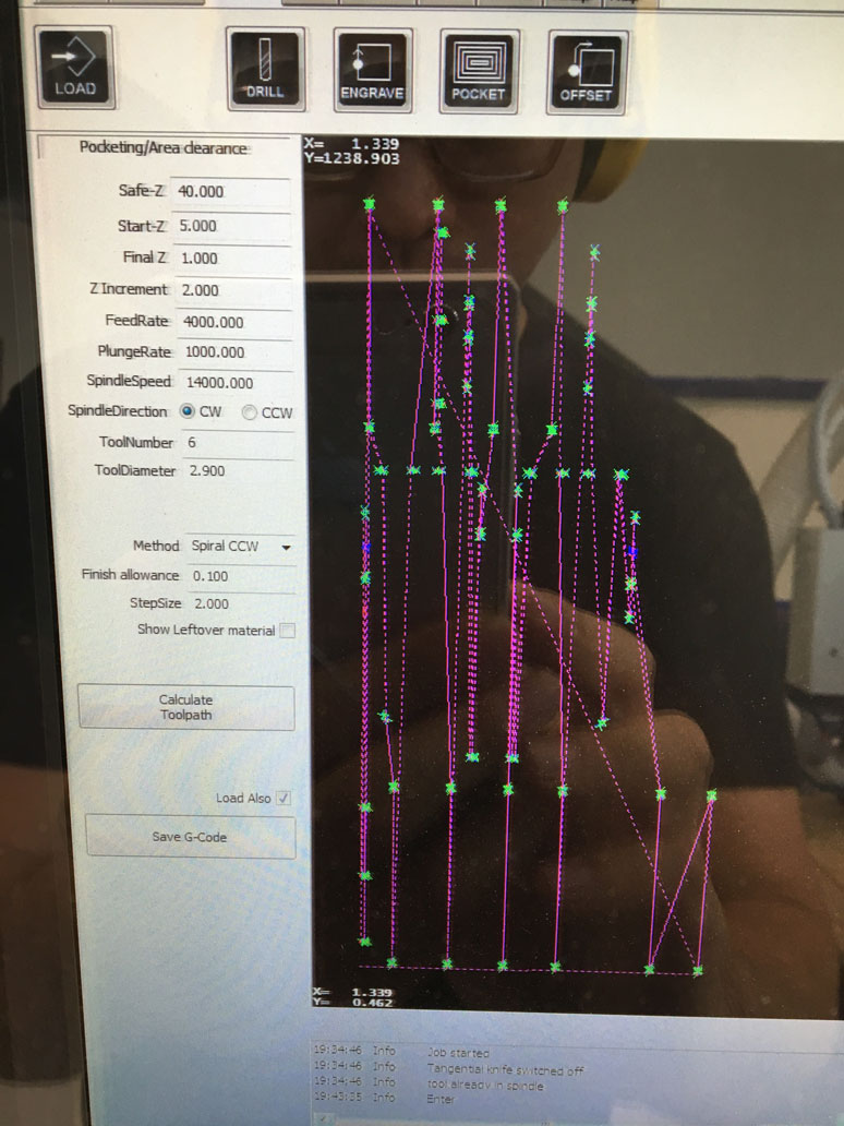
As you can see, each mill pass is rather complex with hundreds of small cuts. It is easy to miss something if the CAM software decides that the shape isn't good enough to mill. It doesn't give much in terms of reporting these errors.
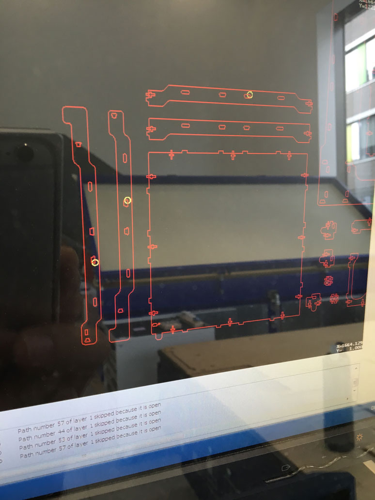
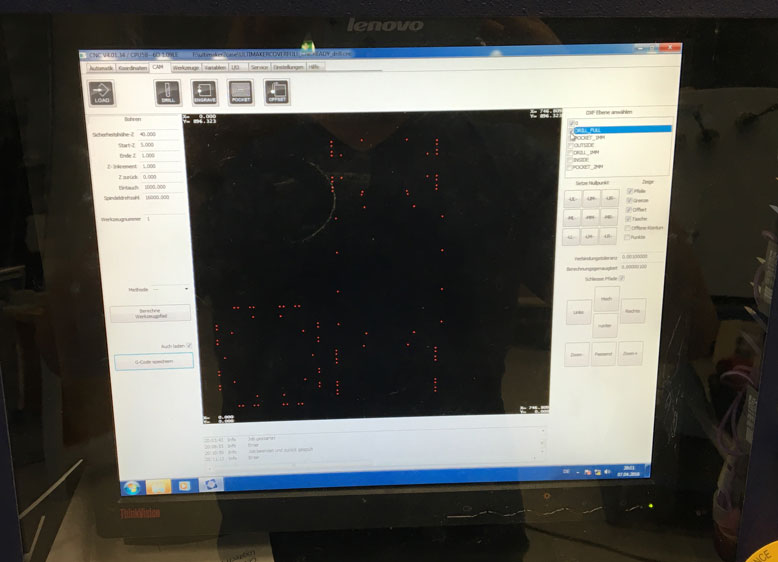
The only errors it does show are during the path calculations. Note that it notes the path number. After looking around in the menu, I found an option to shop open ends in the DXF file on the CAM software. You can see them highlighted in yellow circles on the screen. I then took the DXF file back to Rhino 3D and took a look at the reported shapes. Honestly, they did not differ much at all from any of the shapes. I simply copied and pasted identical shapes from other areas and replaced the problematic ones. This seemed to solve the problem. However, I did run into other problems with larger shapes for the offset cuts. These ones really did not make any sense. I could take the same shape and simply rotate it 180 degrees and the CAM software would magically recognize it, without any changes to the shape itself. I believe this may be some issue with the CAM software itself. Anyways, I found the workaround, however annoying it is and got it to work.
The total milling process took around 4 hours. Here it is compressed to roughly 30 seconds. Only if it worked this fast! You'll notice at one part in the beginning, I had to fiddle around with the cutting bit. This was my first time cutting ABS plastic and I had used the suggested RPM for the bit set to 20000. Unfortunately this was a bit too fast and caused the plastic to melt. At first it wasn't a problem, but as the melted plastic built up on the bit, it widened the bit, causing larger and larger holes to be drilled onto the surface and causing melted burn marks. I had to stop the machine and cut off the melted plastic. I reduced the RPM of the bit to 16000 and the problem went away.
The settings I used for milling the 5mm ABS sheet with the 3mm bit:
- Feed Rate: 1200
- Plunge Rate: 1000
- Spindle Speed: 16000
The settings I used for milling the 5mm ABS sheet with the 6mm bit:
- Feed Rate: 2000
- Plunge Rate: 1600
- Spindle Speed: 16000
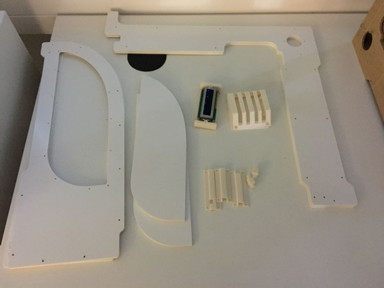
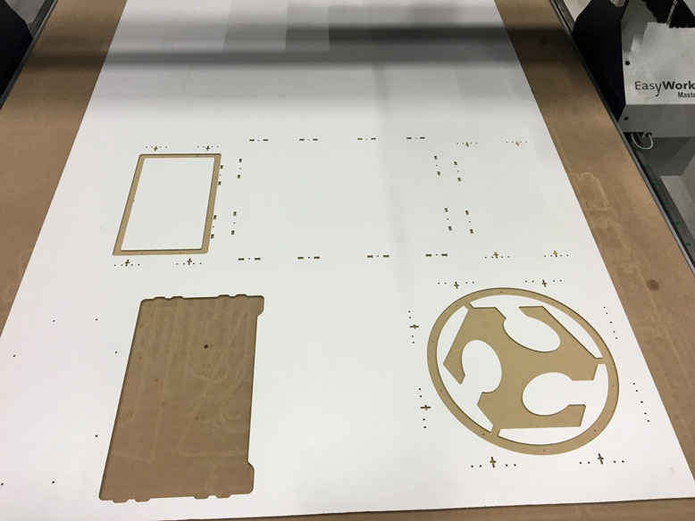
The milled pieces came out beautifully, with only some minor burrs from the bottom where the bit didn't 100% go all the way through the material. Due to the nature of the plastic, I could easily scrape it off with my fingernail and the edge was perfect. Here are the pieces collected. Now, I just need to get the MDF pieces done.
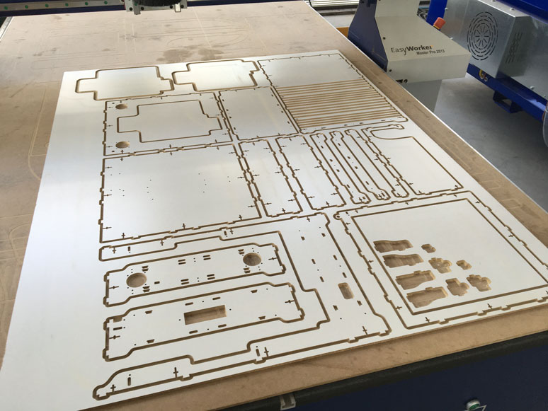
The milling of the MDF went very smoothly due to the past tests I did with MDF. I felt really comfortable handling the material. Midway through the mill, you'll notice some dust appear on the plate. During this portion, I used the 3mm bit to cut out some rather small pieces from the plate. Because the extraction is rather strong, I did not want the pieces that I needed to be sucked away. During this small section, I turned off the extraction and when it was done, I removed the pieces and resumed the extraction. Before when I tried to cut these delicate pieces out using the 6mm bit along with the rest of the objects, the speed and spin rate would eject the pieces and the surface quality of one side would suffer. Using the 3mm to cut out the pieces worked really well.
The settings I used for milling the 5mm MDF sheet with the 3mm bit:
- Feed Rate: 1400
- Plunge Rate: 1000
- Spindle Speed: 20000
The settings I used for milling the 5mm MDF sheet with the 6mm bit:
- Feed Rate: 3000
- Plunge Rate: 2000
- Spindle Speed: 20000
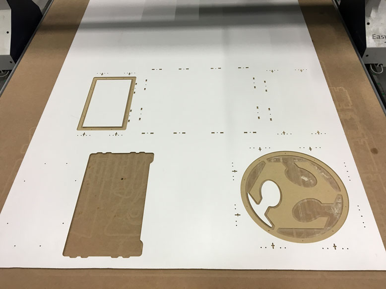
With all the pieces cut out, the contrast of the white and the milled MDF, it's quite the pretty sight. I gathered up all the pieces, which luckily did not require any cleanup at all. One note, during the mill of all the pieces, I had to make sure to think about which face I was milling. Since the DXF files and the sketches could be oriented in either way, I had to make sure I visualised the proper face to be facing up. For symmetrical objects, it is not a big deal, since I could just flip it. When it came to specialized cut and making sure the clean face was facing the correct direction, I had to make some mental wrangling to ensure everything in order. I managed to get everything right except for one piece, which I later recut in the correct orientation.
Phase 6: Assembly
With the hardware ready and functioning, I had to transition it from the test area to the attachment to the final enclosure.
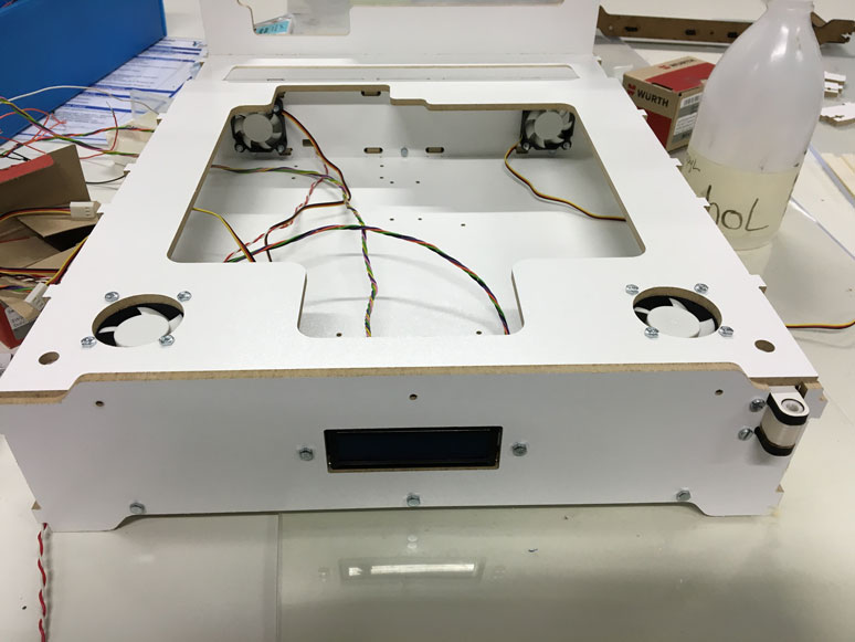
The first piece went on pretty easily. I had 3D printed an LCD mount to seamlessly fit it to the front. I left some space in order to easily reach the attachment points for the cables. It was important for me to make things easily maintainable and attachable/detachable.
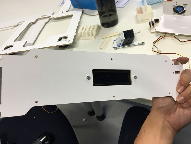
The front was nearly perfect. As I had first used a slightly different LCD screen with a deeper set screen, this one left about a milimeter or two left. If you're not looking for it, you can't really see it. But being the perfectionist that I am, it bother me a lot, but not enough to drop everything and print another mount. So, I just learned to live with it. In the future, I will make the neccessary changes to get it flush. Or else, I may not be able to sleep.
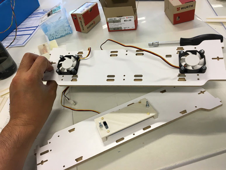
I attached the first set of fans.
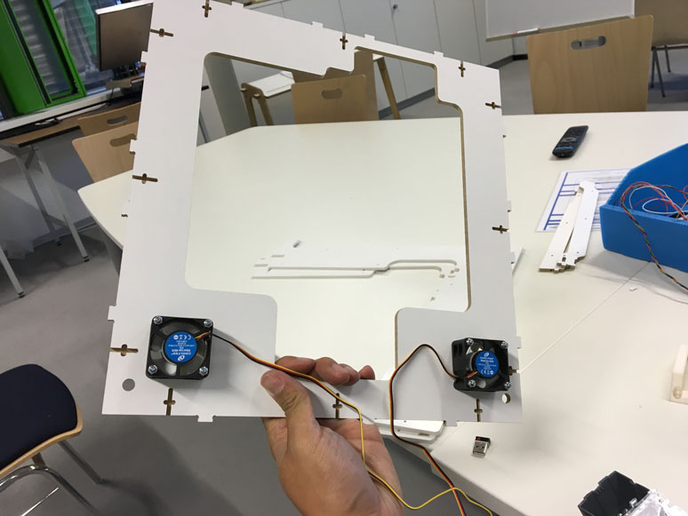
And did the same to the second set.
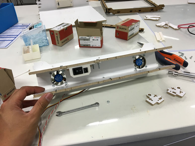
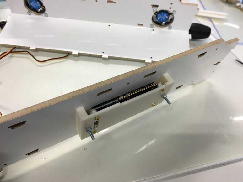
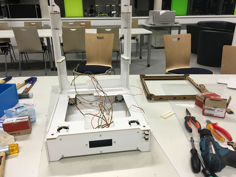
I continued to assemble the rear portion. Shown here is the 3D printed mount for the On/Off switch and the 12v power input. The On/Off switch snapped easily into the opening which I created it for. The power input required a bit of soldering to have it be attached solidly to a pin board. In the future I plan to have a more solid method of doing this.
Assembly continued. I had to logically think through the assembly process, because as the enclosure was built up, it decreased the access one had to previous areas. So if connectors and fasteners were installed out of order, it would cause huge headaches down the line. Luckily the previous full enclosure test gave me insight to the ordering of things.
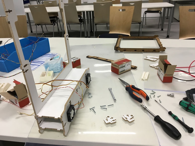
The bottom enclosure was taking shape. I had a handful of tools to assist in the process. The pliers allowed me to insert nuts into the proper spaces where my hands could not fit. As I put things together, I felt I could still do a better job of making the fasteners more accessable. Additionally, I think I overengineered it a little. The fasteners mimicked the patterns from the Ultimaker 2. While the Ultimaker 2 requires to be very sturdy and rigid to maintain precision of the 3D prints, the outside enclosure would not be subjected to so many forces. As I assembled the enclosures, the components felt very sturdy. A tank could have run over them and it would still be standing. This is nice, however it came at a cost of difficulty and time of assembly. Building one would not be a problem, however turning this into a kit or mass producing these enclosures would require a re-design of the fasteners and connectors.
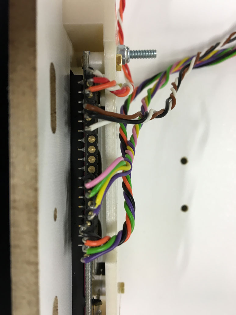
I plugged in the wires I needed for the LCD display. I grouped the pins by function, so it was easy to remember the order to stick them in.
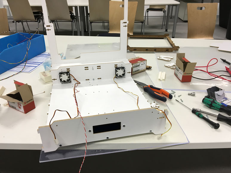
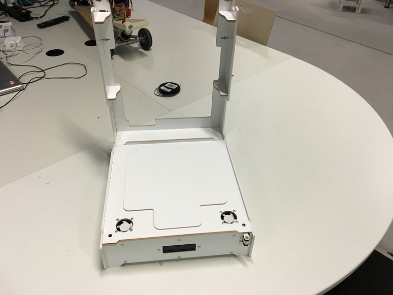
The top piece was attached, and the bottom part was beginning to take shape.
I threaded in the power wires and double checked all the connections. The final part would be the installation of the microchip, the power converter with the connector bus for the fans. Assembly wise, the side panels made from ABS would always be the last pieces to be attached. These pieces lock all the other pieces into place.
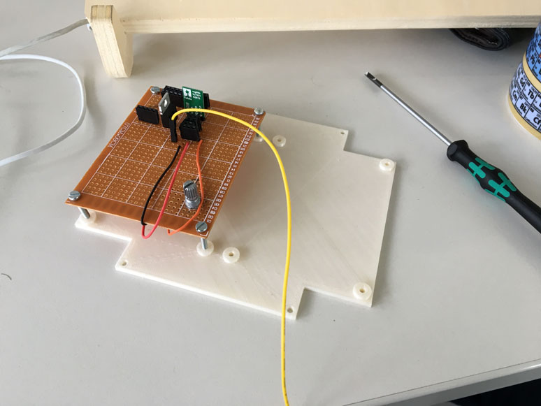
As described in the output assignment, the pinboard with the mosfet and step down converter is a temporary solution until I make adjustments to the hardware system. Nonetheless, I made sure to securely mount it to the mounting plate I 3D printed. On one side is the power distribution board with the contrast knob for the LCD, while the right side is reserved for the satchakit microcontroller package.
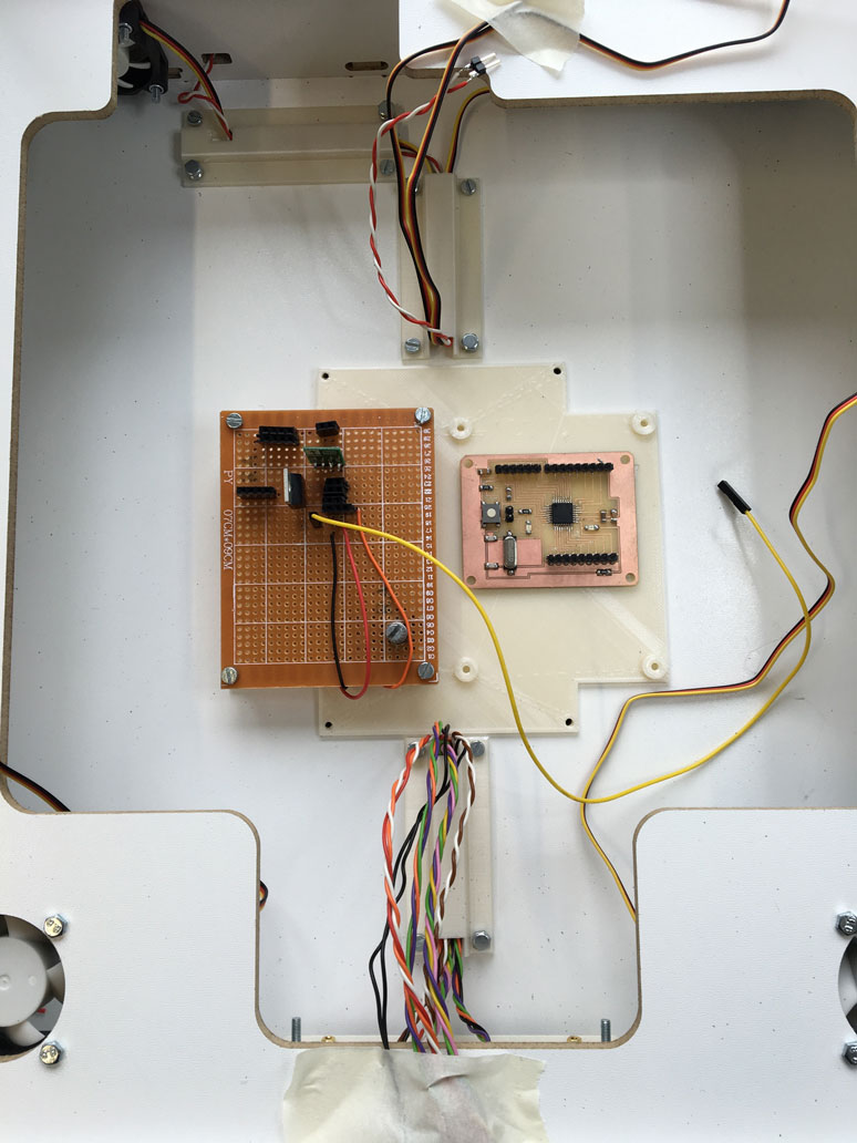
Here is everything mounted into place. In addition, I printed some wire rails to make everything nice and neat. The last thing I wanted was a loose wire to get snagged in a fan or something like that. I only then needed to make all the connections to the power distribution board and the satshakit.
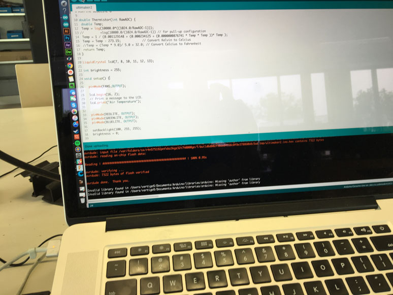
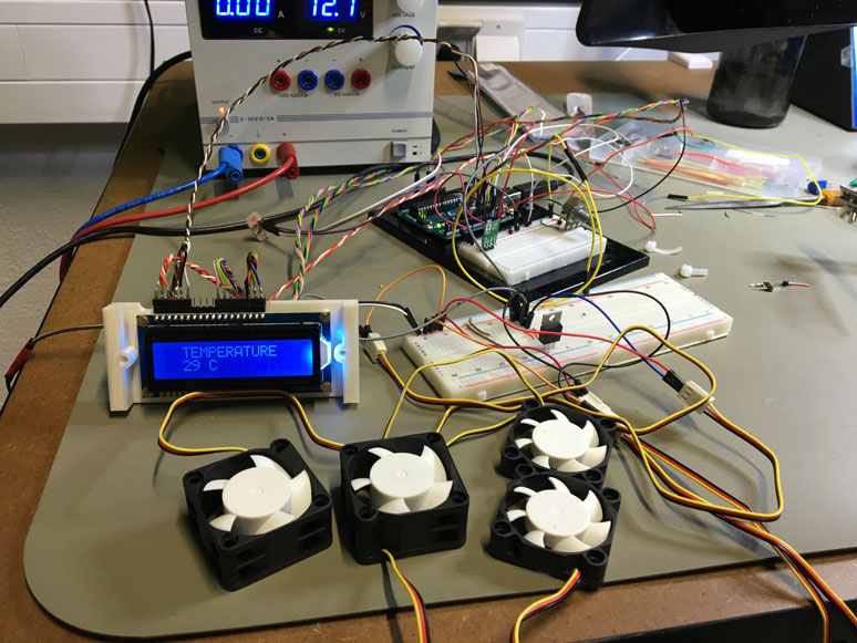
I loaded the code that I had written during the Output device week and hoped everything was connected correctly.
The test was a success! The functionality is basic, but exactly as I had planned. It would require some future tweaks and tests to find the ideal temperature range for proper printing. Right now the temperature sensor is threaded from the bottom into the bed area of the Ultimaker. It functions well there, however it can be sometimes painful to have to disconnect it before the removal of the Ultimaker from the enclosure. So In the future, I plan to thread the thermometer through the back side of the enclosure into the crown area. This way, things should be much easier to disconnect. In addition, the higher placement of the sensor allows for more immediate air temperature readings, as the warm air rises to the top.
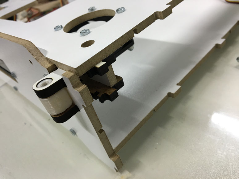
Here is a quick look at the joint system for the door. It is a 3D printed construction that fits into the milled pieces. It is reinforced on three sides to make it robust enough to handle the stresses and forces of repeated use of the hinge. There is a similar but flipped version on the top side of the crown.
To close the enclosure, but still allow access to the electronics, I created a offset lid that fits snuggly and tightly into the open cavity. It is held in place by gravitiy and some slight friction. Since the enclosure is designed to stay in place, this seems like a good enough solution. The side panels fit into place easily, despite there being over a dozen connection points. I had reverse engineered the pocket slots for the tabs in which there were some that allowed for vertical slack, while others inline allowed for horizontal slack. The combination of these along with the bolt connectors created a sturdy connection while allowing the mating of the tabs to be done in a relatively easy manner.
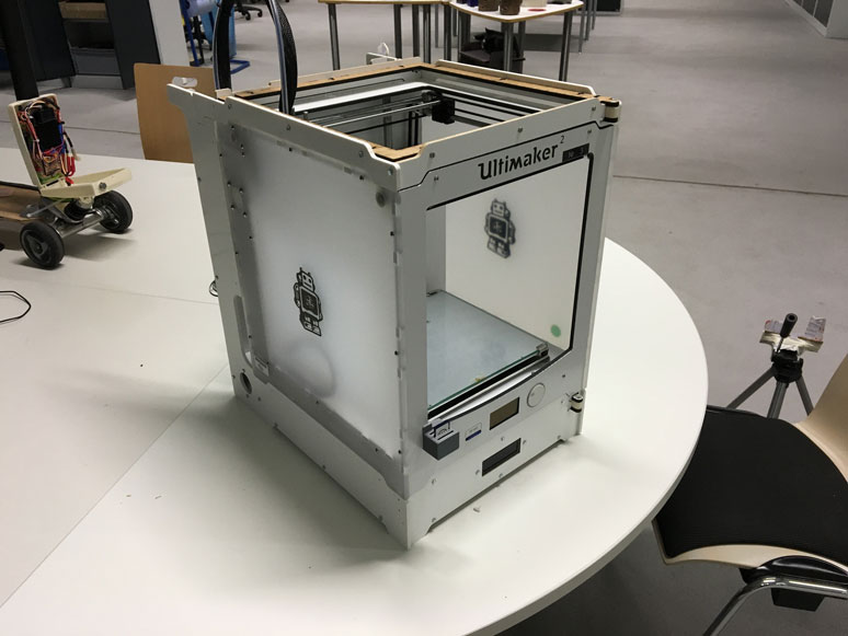
I finished the assembly of the crown and place the Ultimaker 2 on the bottom enclosure and affixed the crown into place. The back side of the crown interlocks with the bottom portion to create a slight friction and tension hold. This prevents the crown from flipping forward if the door is pulled too hard.
The assembly of the top cover was actually simpler than the bottom enclosure. The only hard part was the kerf curve. The material was quite strong, so it took a little bit of muscle to align everthing into place. Overall, not too difficult. It just requires a little bit of control and patience. The top fit on perfectly and the assembly was complete.
I awaited for better light and prepared the machine for a test print. All in all, the project was a success. There is still much to do to make it a real marketable product. However, in the mean time we have already gotten bennefits from the project, as a student from another school needed to make some large models using ABS. I did a couple of trials with out the enclosure and some with. The ones with the enclosure yielded much better results due to the lack of warping in the ABS. I really look forward to doing more tests and tweaks to the system when time allows.
Files
- Ultimaker 2 Enclosure - DXF Files
- Ultimaker 2 Enclosure - Fusion 360 Files (Note Preview does not show enclosure bodies, as only sketches were used)