Week 14: output devices
April 27 - May 3
Assignment
- Add an output device to a microcontroller board you've designed and program it to do something
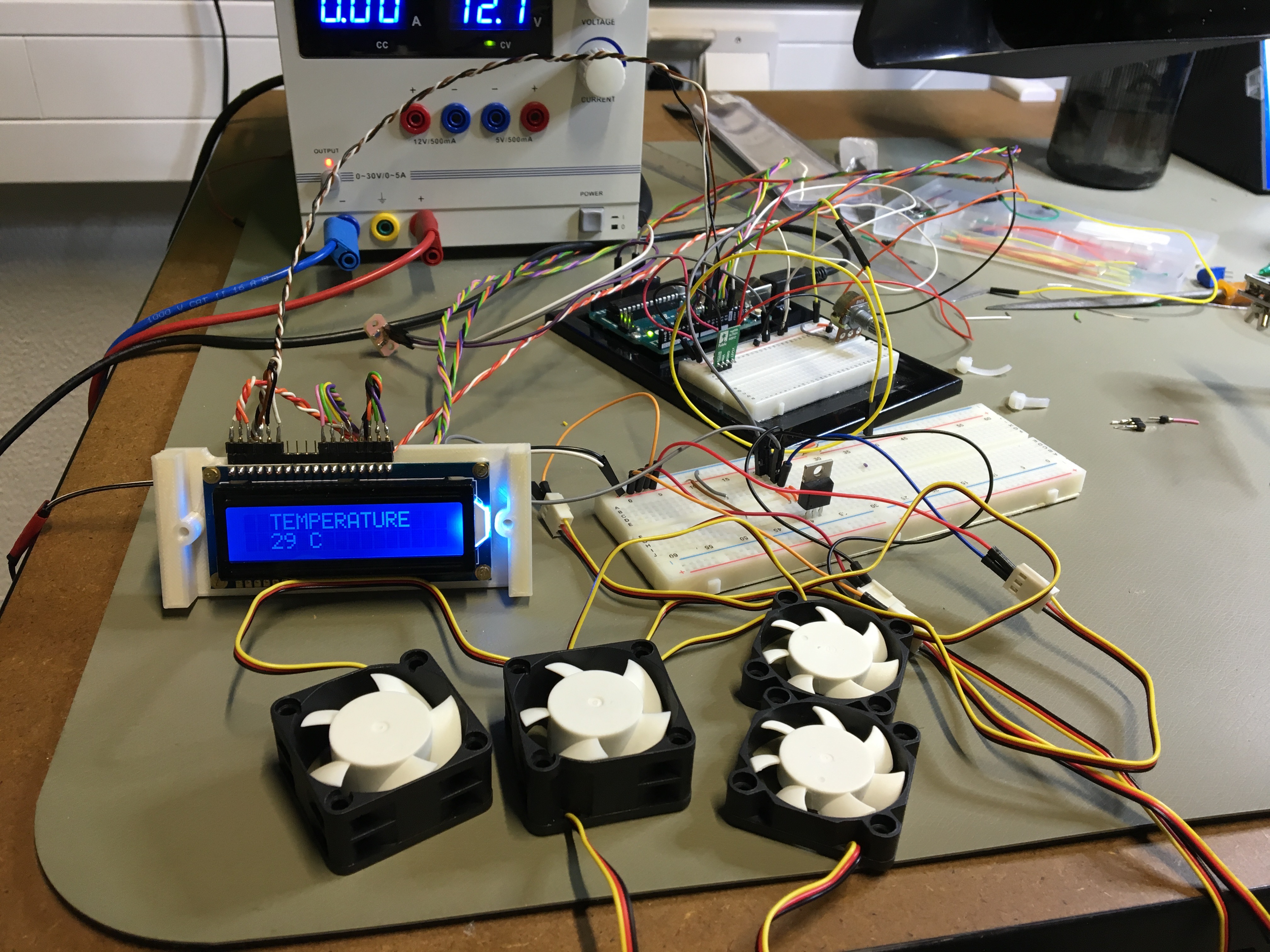
For the output device assignment, I figured it would work perfectly into my final project. The goal is to use an thermistor input to signal when the fans should turn on and off. In addition I wanted a RGB LCD screen to display the current air temperature. The setup for this was pretty straightforward with the use of the instructions found on the Adafruit site. It includes basic wiring of the module along with example code which I used to get this simple interaction working.
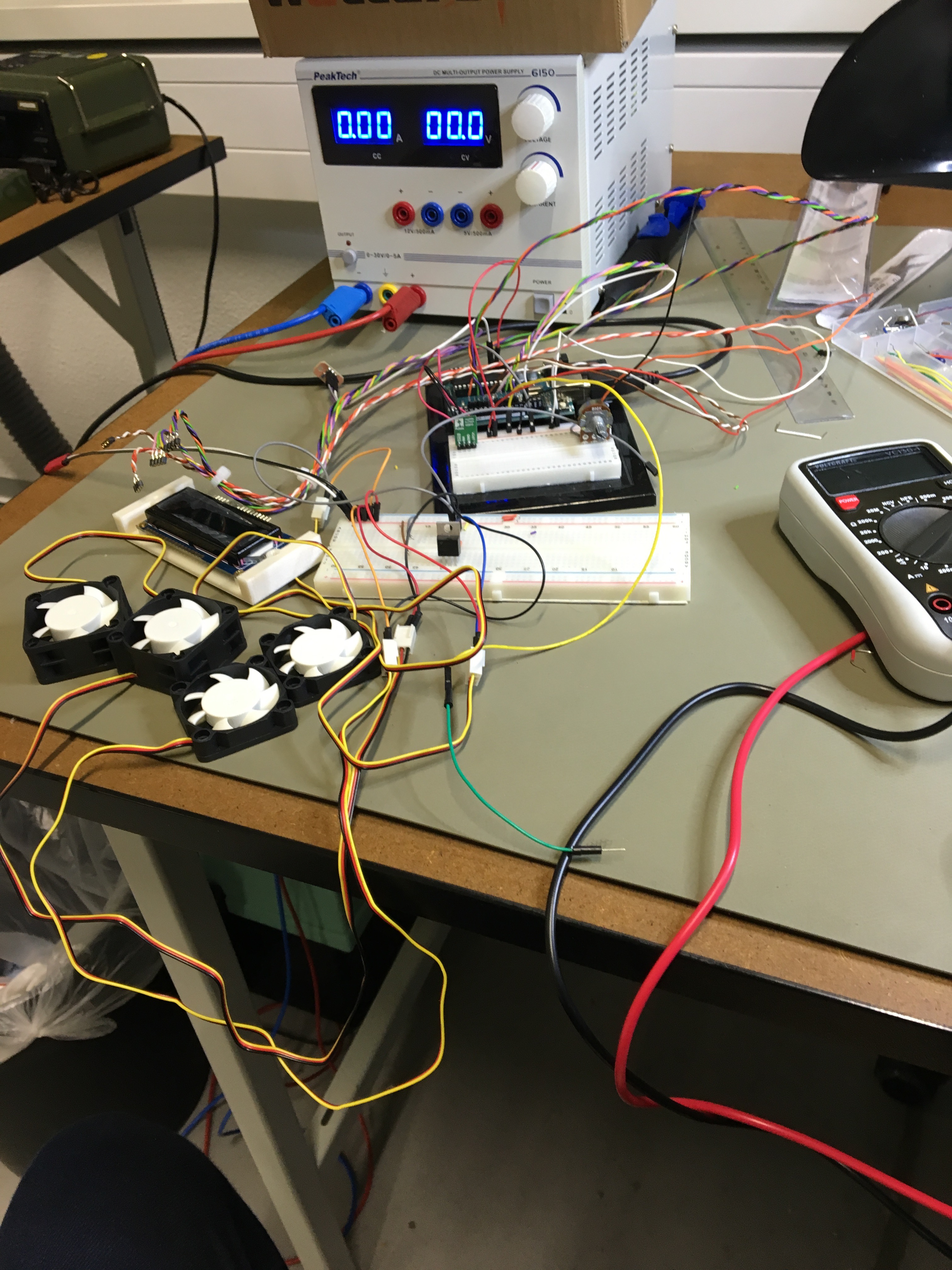
I first created the setup using solderless breadboards and a power supply, just to make sure everything is working. One hurdle was that to power the fans, I required 12 volts, while the rest of the components such as the satshakit and LCD required only 5 volts. To achieve this, I used a step down converter. The second hurdle was that while I thought I could control the fans with PWM using the third wire, I could not, because the third yellow wire only served as an RPM output. For PWM controlled fans, I required more expensive 4 wire fans. So in order to control the on/off and speed of these fans, I turned to a mosfet. Since I only required all fans to function together instead of separately, a single mosfet was enough.
After a few hours of wrangling with wires, I got the system up and running. I had to make sure that the 12v and the 5v were indeed separate, however I needed to make sure all the separate components shared the same ground in order for the information to properly pass between them.
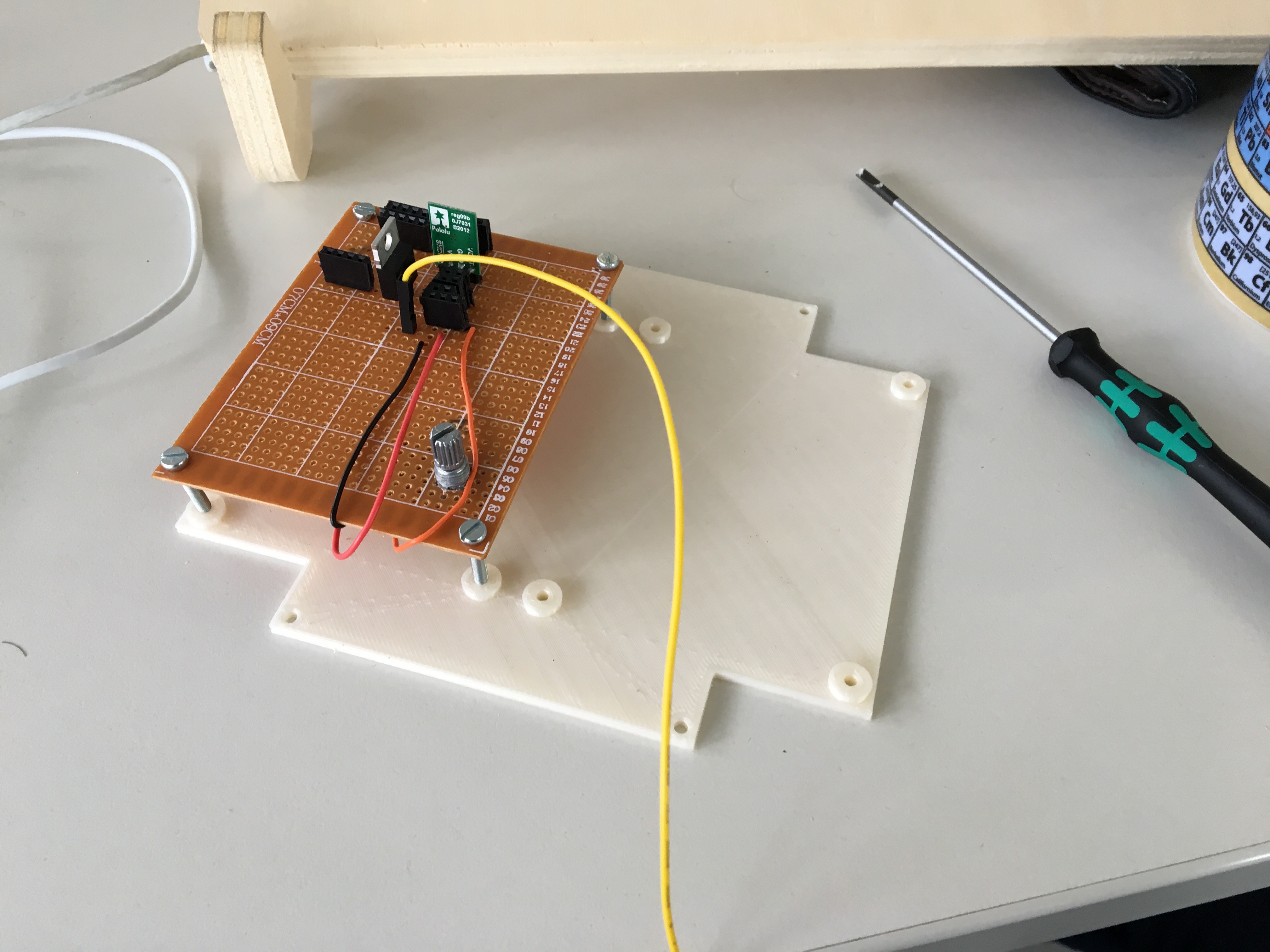
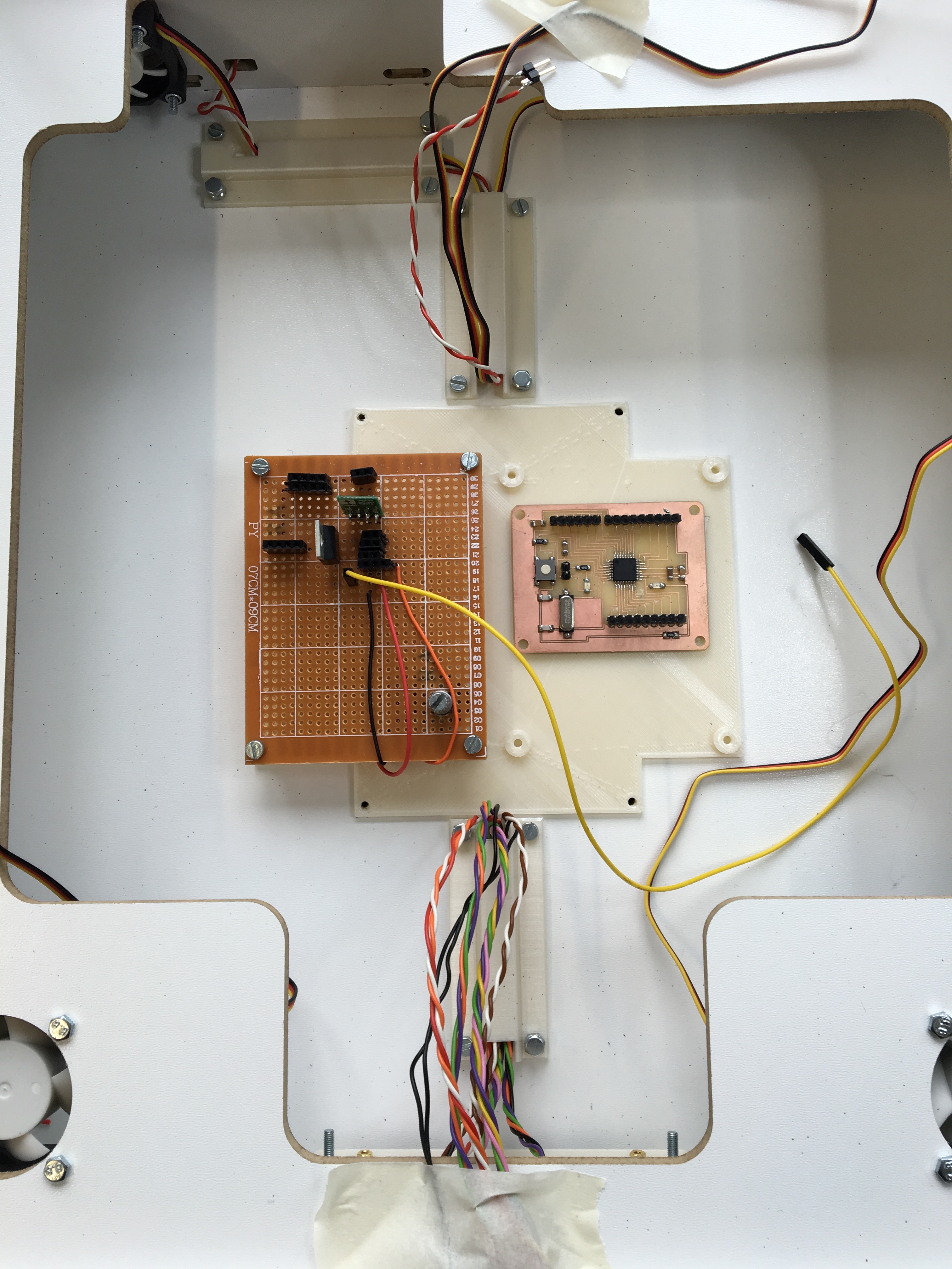
I knew this was not the final iteration of the functionality, so I decided to just quickly solder the components onto a pin board. I had already 3D printed a mount for these components, so it was rather easy to get it on there.
Here it is mounted into place before all the wiring was connected. The potentiometer was necessary to control the contrast level of the LCD.
For a quick test, I set the threshold to 30 degrees. Using my hand to warm up the thermistor, I was able to get an accurate readout of the temperature and activate the fans. Below is the code I used, which is hacked together from the example code of the Adafruit tutorial and the Arduino thermistor code from before.
#include <LiquidCrystal.h>
#include <Wire.h>
#include <math.h>

#define FANS 9
#define REDLITE 3
#define GREENLITE 5
#define BLUELITE 6

double Thermistor(int RawADC) {
 double Temp;
 Temp = log(10000.0*((1024.0/RawADC-1)));
//         =log(10000.0/(1024.0/RawADC-1)) // for pull-up configuration
 Temp = 1 / (0.001129148 + (0.000234125 + (0.0000000876741 * Temp * Temp ))* Temp );
 Temp = Temp - 273.15;            // Convert Kelvin to Celcius
 //Temp = (Temp * 9.0)/ 5.0 + 32.0; // Convert Celcius to Fahrenheit
 return Temp;
}

LiquidCrystal lcd(7, 8, 10, 11, 12, 13);

int brightness = 255;

void setup() {

  pinMode(FANS,OUTPUT);

  lcd.begin(16, 2);
  // Print a message to the LCD.
  lcd.print("Air Temperature");


  pinMode(REDLITE, OUTPUT);
  pinMode(GREENLITE, OUTPUT);
  pinMode(BLUELITE, OUTPUT);

  setBacklight(100, 255, 255);
  brightness = 100;

  Serial.begin(115200);
}


void loop() {

Serial.println(int(Thermistor(analogRead(0))));
delay(1000);

  lcd.setCursor(0,1);
  lcd.print("    ");
  lcd.print(int(Thermistor(analogRead(0))));
  lcd.print(" C");

if (int(Thermistor(analogRead(0))) > 30)
  {
    analogWrite(FANS, 150);
    brightness = 255;
  }

else
  {
    analogWrite(FANS, 0);
    brightness = 0;
  }
}

void setBacklight(uint8_t r, uint8_t g, uint8_t b) {
  // normalize the red LED - its brighter than the rest!
  r = map(r, 0, 255, 0, 100);
  g = map(g, 0, 255, 0, 150);

  r = map(r, 0, 255, 0, brightness);
  g = map(g, 0, 255, 0, brightness);
  b = map(b, 0, 255, 0, brightness);

  // common anode so invert!
  r = map(r, 0, 255, 255, 0);
  g = map(g, 0, 255, 255, 0);
  b = map(b, 0, 255, 255, 0);

  analogWrite(REDLITE, r);
  analogWrite(GREENLITE, g);
  analogWrite(BLUELITE, b);
}