Week 9: mechanical design, machine design
March 23 - 29
Assignment
- Make a machine, including the end effector
- Build the passive parts and operate it manually
piXel Planter Extruder
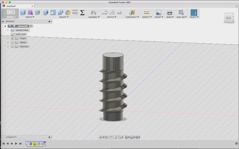
After doing some tests to find the simplest solution for a seed extruder, we came up with using a screwlike device to agitate the seeds to allow gravity to drop the screws in a controlled manner. So, therefore the first thing to make is a cylinder in Fusion 360 that I applied a screw thread to. I adjusted the size of the thread to better fit our needs.
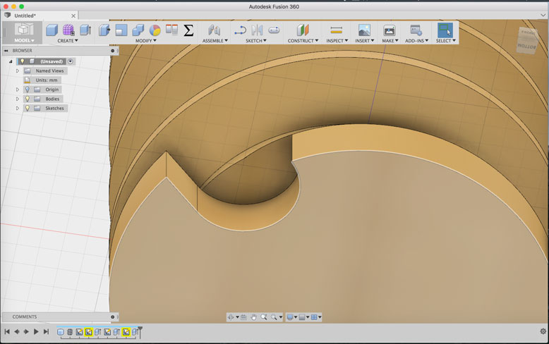
When the cutout slot of the screw aligned with a hole in the extrusion head, only a certain amount of seeds would be expelled. Of course there will be a small variance, but for this task this was acceptable. I used the bevel tool to smoothen some of the hard edges to prevent grinding and binding of seeds.
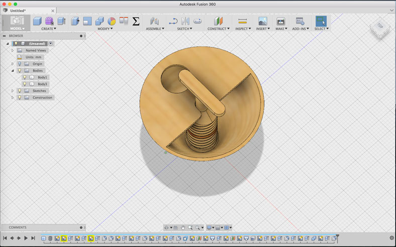
Next came the design for the hopper for the seeds. It needed to be designed as separate bodies, as these will be 3D printed. It was important to think about how the pieces fit together. In the digital world, it is easy to get lost in the ease of movement. In the physical world, things need clearances in order to enter the proper areas, so it took a bit of mental gymnastics to make sure I did not create any impossible fittings.
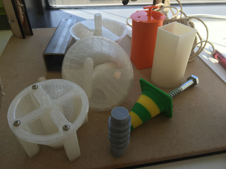
The design process is iterative. I did various tests in different sizes, materials, and fitting types. Here are a few of the pre-prototypes.
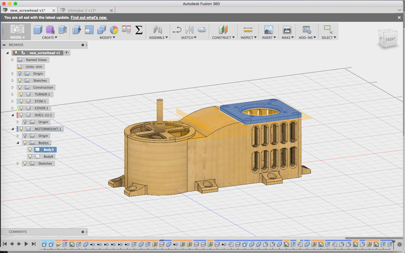
Once the proper size and method was found, I applied the design to a more complete system, which included the mount for a stepper motor to control the extruder head. In addition, mounts were made for future attachment to the frame.
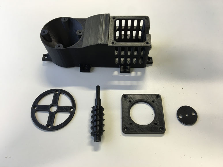
Here it is in the physical form. Printed in ABS plastic, the frame is very solid with only slight warping due to lack of temperature control on the printer. The functionality worked well after some seed extrusion tests.
piXel Planter Frame
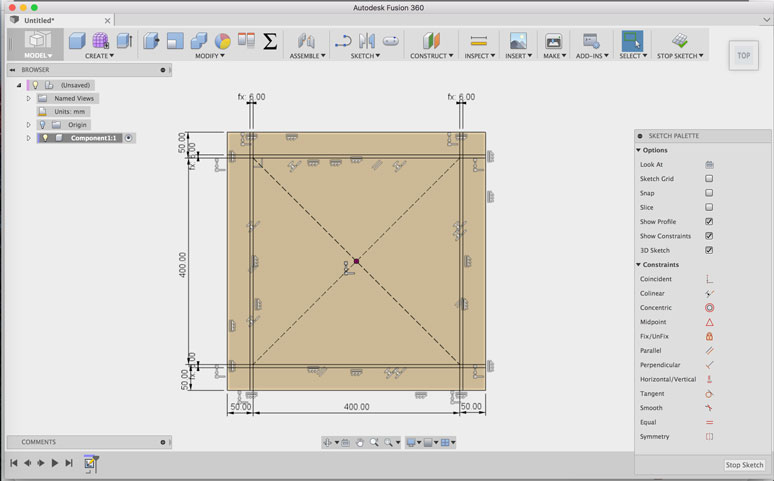
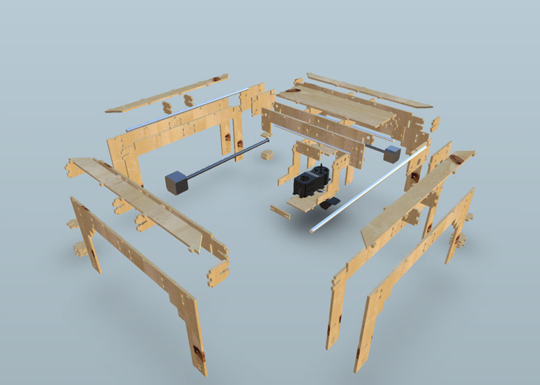
After many attempts to convert a previous FabAcademy frame design to suit our needs, it was decided that it would take just as much work to make the adjustments than to design our own. The design is made in Fusion 360, starting out with basic sketches to plan everything out.
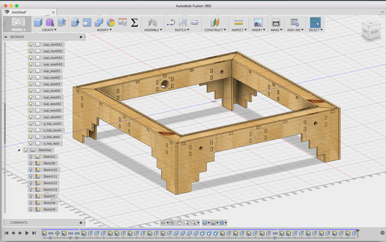
The sketches, once properly constrained are then extruded out to create a three dimensional representation of the frame. It was also important here to make sure there weren't any impossible connections. I took care to make sure all nuts and bolts were accessable during setup. Reinforcements were placed where required, and the machine moving mechanisms where designed to function as intended. The addition of sliding joints and physical contact constraints allowed the movements to be simulated first in a digital environment.
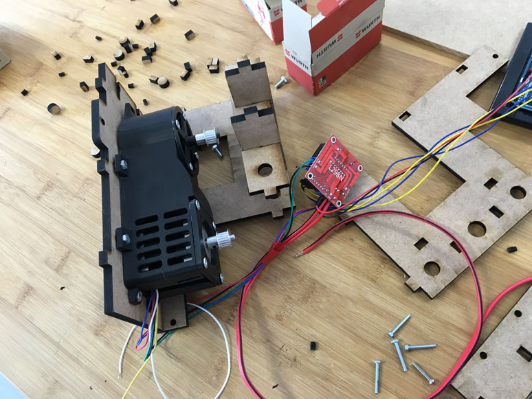
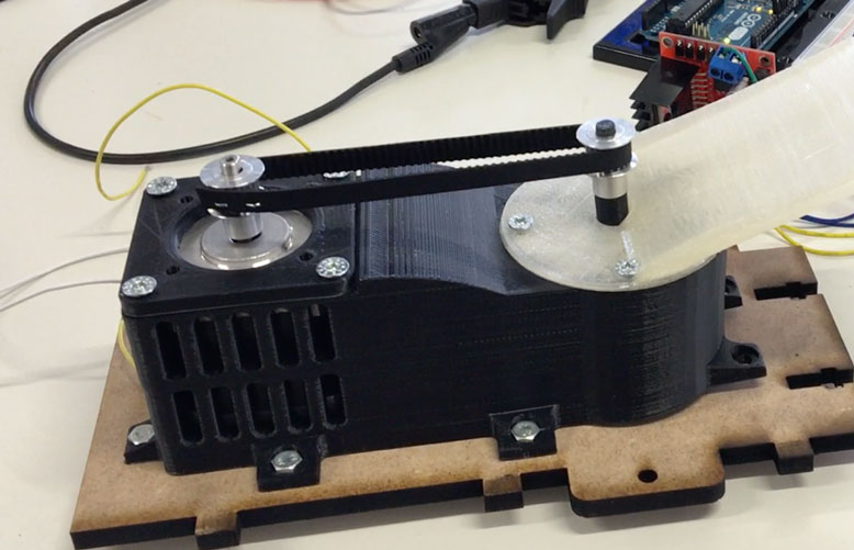
The attachment of the extruder module to the y axis frame holder
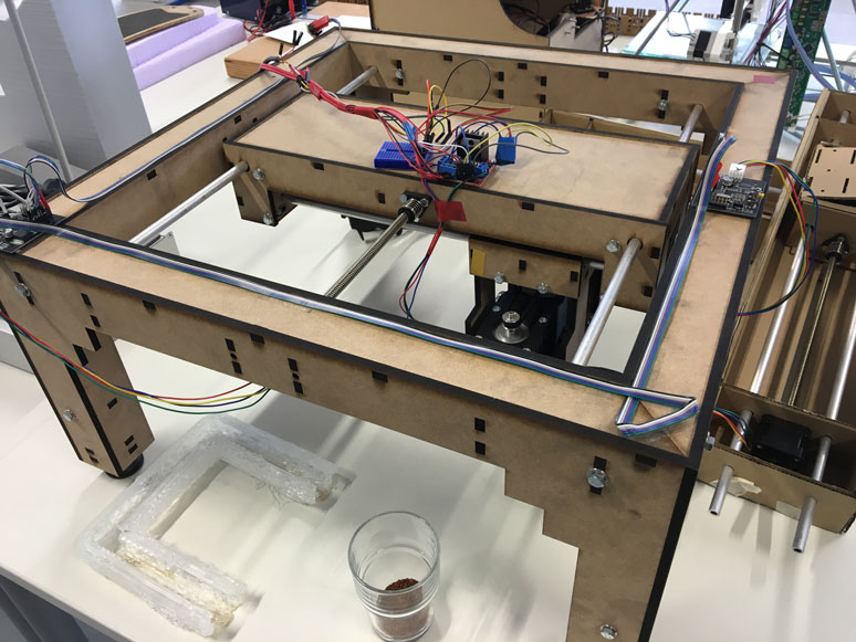
The final frame with all electronic components. See further details and construction of the machine on the group page