Week 8: embedded programming
March 16 - 22
Assignment
- Read a microcontroller data sheet
- Program your board to do something, with as many different programming languages and programming environments as possible
ATtiny24/44/84 Datasheet

I selected an ATtiny24/44/84 datasheet to read for this assignment. I did so because I had some experience in the past using this chip to control neopixels without a full Arduino board. The initial page looked promising. As a designer with no electrical engineering background, most of these features presented did not offer me anything, however I saw how in the future if I needed specific functions, this would be a very clear place for me to find that information.
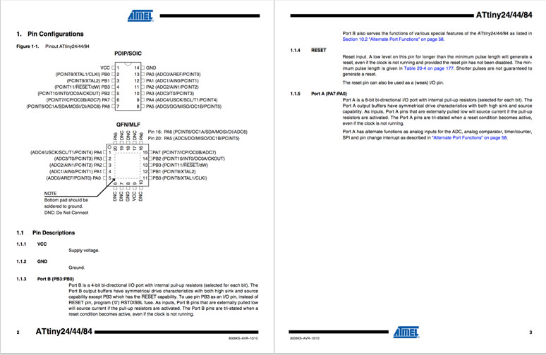
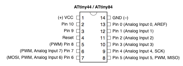
Continuing to the pinouts, I can easily identify the power and ground connectors as well as the orientation marker for the chip. This would be important to note when soldering, as there are no other clear markers present on the chip. However, I could quickly start to tell that this document is created by engineers for engineers. There is a lot of shorthand, identifies, and numbers that may have some mystical meaning to an engineer, but to the lamen it's pretty much mumbo jumbo. Following a tutorial though, I would be able to set up a proper schematic using the pinouts provided. And at least they attempt to give definitions to some of the terms.
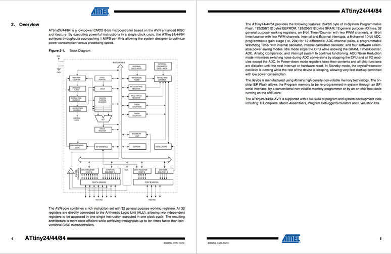
This is where it starts going off into the deep end. Neither the diagram, nor the text have any meaning whatsoever.
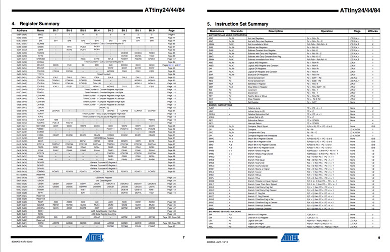
On pages like this, my eyes glazed over. These pages could have been various pictures of ham sandwiches and it would have been equally as useful.
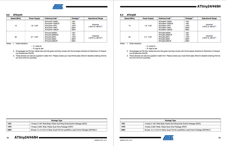
The conclusion is, that in order to properly parse the information in a sheet like this is drop everything and take four years of electric engineering, or have someone sit next to you to help you parse the information. These sheets are not consumer facing, they are meant only for experts in the field. In the meanwhile, there are plenty of other sources through Google search that yield the information needed that does not require the parsing of a datasheet such as this.
Hello World Board
To program the Hello World Board, I used female-female cables to connect the serial pins from the programmer to the board. It was important to make sure the orientation was double checked, as there are no visible indicators on the programmer or the board itself. The best way to do so was to check the EAGLE board files, so it was useful to have them printed out and available. The programmer was attached to the laptop via USB cable.
Before starting, I had to append the make file with the following to allow programming access via the Arduino IDE:
program-arduino: $(PROJECT).hex
avrdude -p t44 -b19200 -P /dev/ttyACM0 -c stk500v1 -U flash:w:$(PROJECT).c.hex

program-arduino-fuses: $(PROJECT).hex
avrdude -p t44 -b19200 -P /dev/ttyACM0 -c stk500v1 -U lfuse:w:0x5E:m
Then I used the terminal to execute the following commands:
make
make program-arduino-fuses
sudo make program-arduino
Demonstration
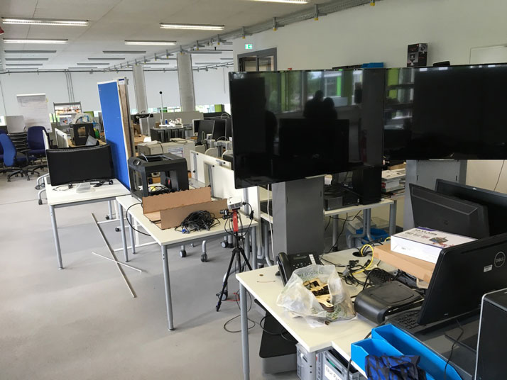
Sometime after the Hello World Board was created, we received a large shipment of new furniture for our lab. This required us to compress all the items and equipment to a small section of the lab in order to install the new fixtures. Unfortunately, a result of this large and hectic moved left the Hello World Boards lost in the ether.
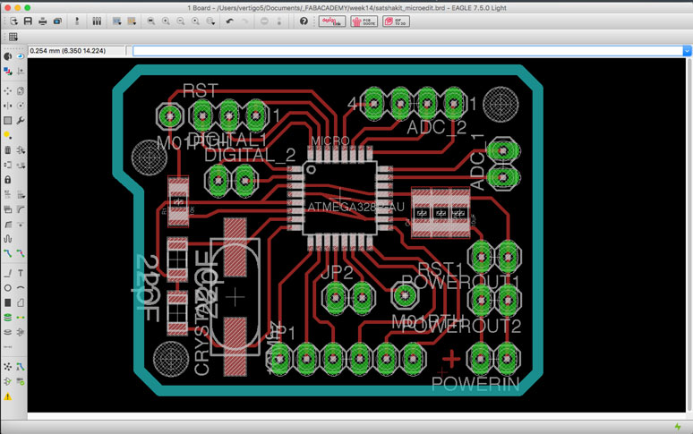
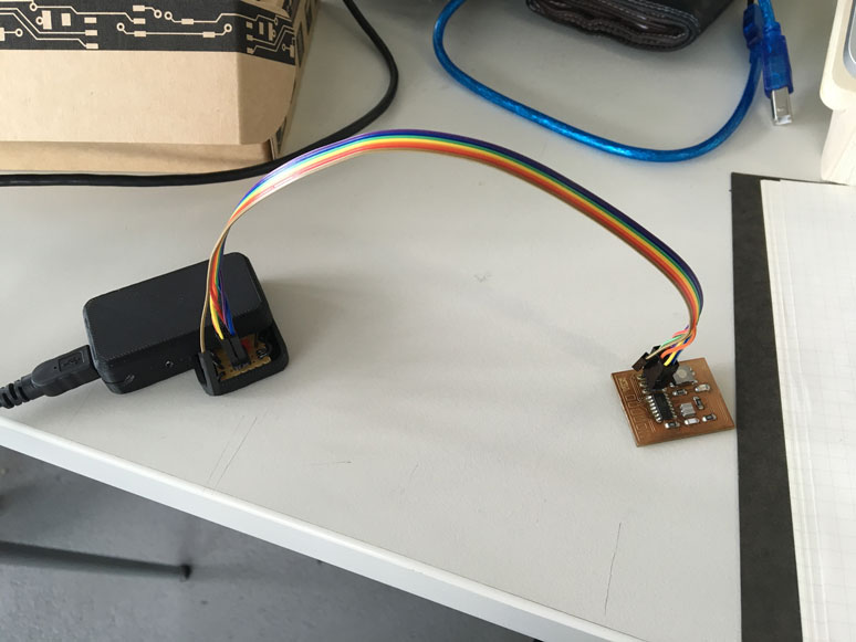
So in order to record the required videos for the demonstrations of the code I decided to mill a self modified Satshakit micro to do so. I felt it would have a bit of a waste to produce another single use board for this task. With the Satshakit micro, I could use it in future projects.
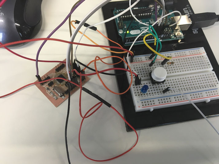
To demonstrate the code, I attached an LED and a button to the Satshakit micro and as per the instructions used an Arduino to program the board and use it as a power source. Note, all of the code and processing is done by the Satshakit, not by the Arduino. So relax.
Once this was set, the board could easily be programmed with the Arduino IDE. I ran a simple program that would turn on the LED when pressed. The code is as follows:
#define LED 10
#define BUTTON 7

int buttonState = 0;

void setup() {

pinMode(LED, OUTPUT);
pinMode(BUTTON, INPUT);

}

void loop() {

buttonState = digitalRead(BUTTON);

if(buttonState == HIGH)
  {
    digitalWrite(LED, HIGH);
  }

  else
  {
    digitalWrite(LED, LOW);
  }

}
This is a slight modification of the previous code that makes the LED blink when the button is pressed until it is released.
#define LED 10
#define BUTTON 7

int buttonState = 0;

void setup() {

pinMode(LED, OUTPUT);
pinMode(BUTTON, INPUT);

}

void loop() {

buttonState = digitalRead(BUTTON);

if(buttonState == HIGH)
  {
    digitalWrite(LED, HIGH);
    delay(100);
    digitalWrite(LED, LOW);
  }

  else
  {
    digitalWrite(LED, LOW);
  }

}