Week 7: computer-controlled machining
March 9 - 15
Assignment
- Make something big
Fusion 360
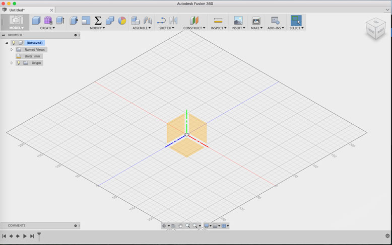
To tackle this challenge, I turned to Fusion 360. Originially I had planned to learn Solidworks, but because I am using a Macbook, Fusion 360 filled all the requirements of what I wanted to learn from Solidworks. This is my first CAD software, and designing with it requires a different mindset. The learning curve was a bit steep, but running through some tutorials eased the process.
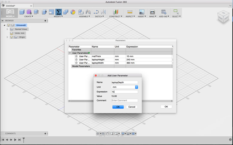
The most exciting part was learning to design parametrically on a large scale. Fusion 360 allows the ability to create user parameters, which then can be applied to your sketches. This allows one source for making changes that cascade through the rest of the design. Designing this way takes a lot of forethough and orginization, but the end result is great.
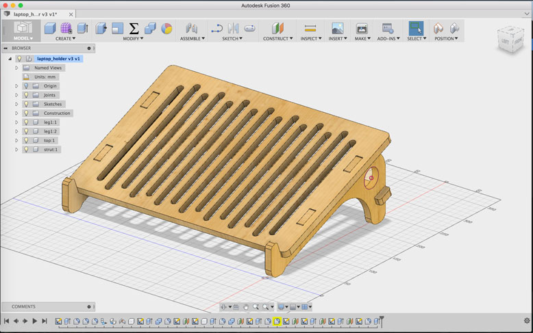
Initially I had big plans in creating something large and complex, but it quickly dawned on me that the amount of time required to learn the program and the slow speed of design with an unfamiliar program, that it would be too much to do in a week. So instead I turned to modifying a laptop tutorial design to something closer to my personal needs.
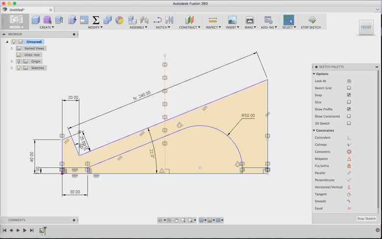
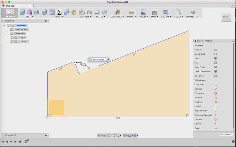
The design starts with a sketch, and it is important to use constraints and dimension tools to lock down certain angles and sizes. Parametric dimensions were used for things such as material thickness and slot length.
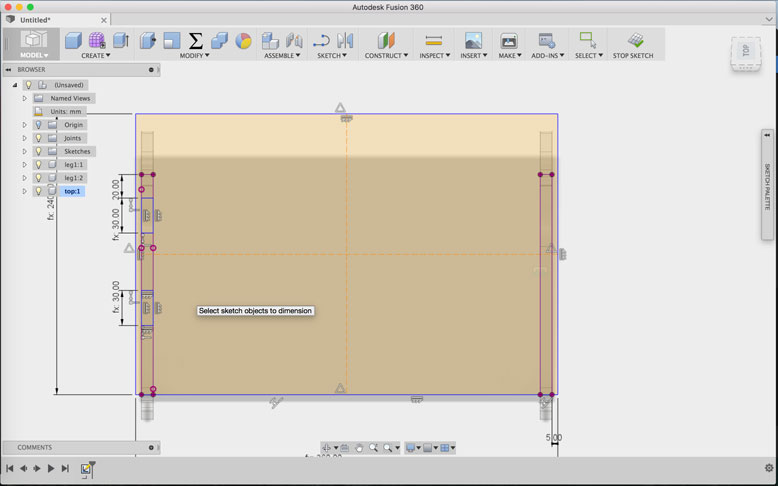
The holes for the slots are created on the top piece by using projected lines from the legs in order to get the proper positioning. Guidelines run across the middle vertically and horizontally to create mirroring lines. The slot holes are mirrored first vertically, then horizontally to create the four neccessary holes without too much additional holes.
Additionally, vertical slots were created and then projected through the surface of the top piece to create a bit of ventilation for the laptop and as well give the object visual interest.
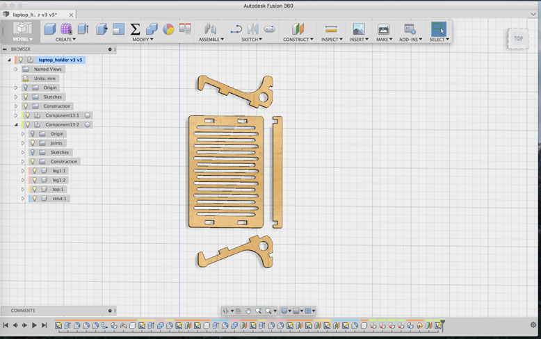
To get the appropriate DXF file that is needed for the CNC, made a copy of the model and used that copy to lay each component flat on a plane. I did not worry too much about keeping them tight to conserve material, as I would do this at a later step.
To get all shapes onto one sketch, I created a sketch on a horizontal offset plane and projected each body onto this sketch.
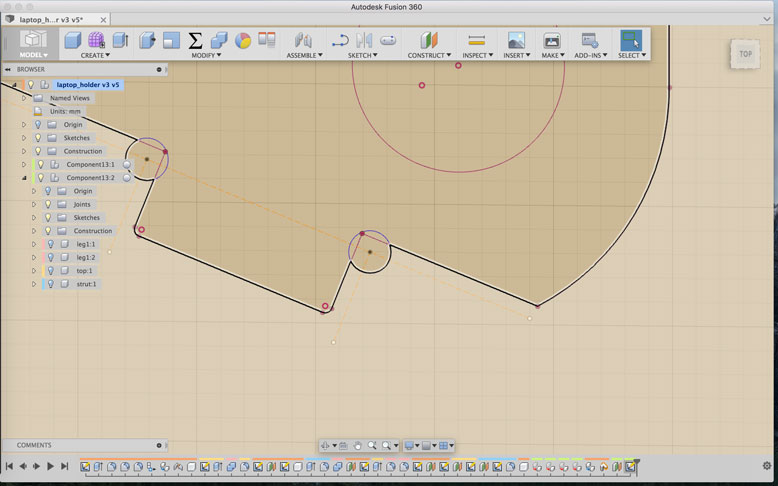
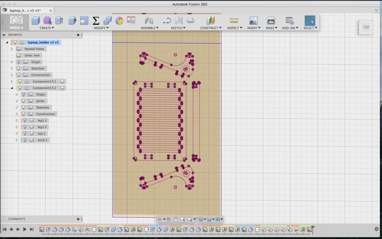
It was at this point I added in the required dogbones so that the corners would fit into each other. Without these dogbones, the round bit would leave behind material where the sharp edge would be. If that would occur, the pieces would not fit. For these dogbones, I created an offset from the edges in order to get the perimeter of the circle to intersect the edge point. This optimizes the surface area available for the press fit and decreases the noticiablity of the created dogbones. The offset varies depending on the size of your dogbone holes, but it is easy to figure out with some trials.
CNC Machine
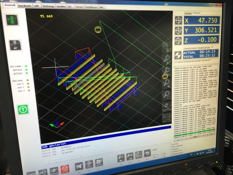
The CNC milling machine that we have in the lab is a elsign EasyWorker Master Pro. It is a powerful and robust machine, however the CAM software is not exactly user friendly. To get the machine to recognize the files, the DXF files needed to be first processed. Each individual type of cut needed to be on its own layer with its own color selection. To do this, I exported the DXF file from the Fusion 360 sketch and then processed it with Rhinoceros 3D. I split the cuts into the following:
- 3mm Drill - Using a 3mm bit, I would drill the dogbone holes
- 6mm Inside Offset - For speed, I used a larger 6mm bit to create the slots and cutouts. The inside offset ensures that the cut follows the inside of the vector line, leaving the outside material intact
- 6mm Outside Offset - The same 6mm bit is then used with an outside offset to release the pieces from the rest of the plate
Dealing with the actual cut settings itself, some basic settings included:
- Safety Height: 40mm - The height which the machine will go to on the Z axis when it is not milling
- Start-Z: The height of the material used
- Final-Z: The depth at which the milling will go, in this case it was set to -0.2 to ensure cuts went all the way through
- Feed Rate: 2000 - Not applicable to drilling, this is the speed at which the mill moves on the XY axis, essentially the speed of the cut
- Plunge Rate: 1000 - How fast the milling head moves down into the material on the Z axis
- Spindle Speed: 14000 - How fast the bit spins on the milling head
- Tool Diameter: Set according to the bit, as most are slightly smaller like 2.9mm or 5.95mm. Use this to fix the offset.
It is very important to to double check the proper settings, as the machine will do what you tell it to do, and with the power that it has, it is capable of destroying itself and its components if the settings are incorrectly inputed

Once the machine starts, it is important to turn on the extraction and to keep an eye on the process. Improper speeds can lead to fires. The environment during milling is quite loud, so proper ear protection is neccessary.
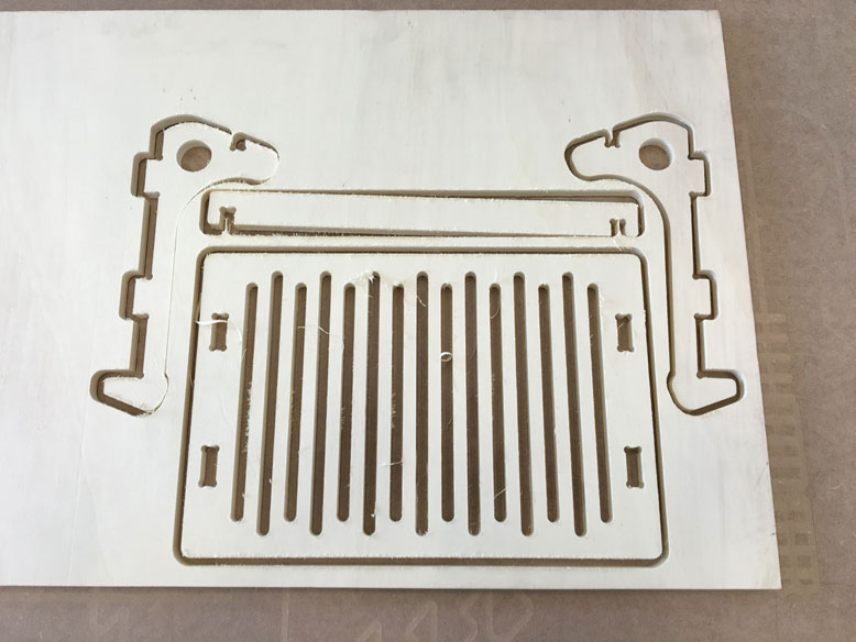
Once the milling process is complete, the parts are ready for removal. The material was held into place by a vacuum, so once that was turned off, they were very easy to remove. As you can see, proper layout placement of the pieces is best used to be efficient with material use.
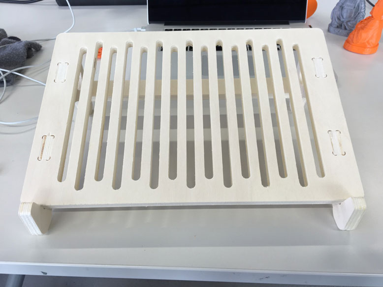
The parts were lightly sanded and press fit very easily into place. The tolerances were exact and with a little bit of give from the wood, the pieces fit together very strongly.

The measurements were correct and the laptop fits snugly and securely on the stand.
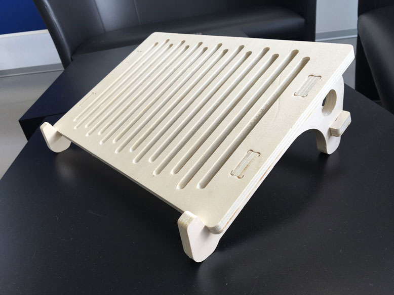
Others were intrigued by the design and usage, so I ended up making four more for others, using the parametrical design to accomodate different laptop sizes and material thicknesses.