The Concept
This weeks assigments (week 09 + 10) are about Mechanical Design & Machine Making. This time it is a group task in which we have to build a machine that MAKEs something.In our team at FabLab Kamp-Lintfort we did brainstorming and came up with some nice ideas. To foster a decission we classified them by dimensions of: crazyness/ practicability and hardness/easyness.
The outcome of the process can be found here
At the end we decided to do a serious but not to serious machine that MAKEs fun to MAKE.
THE "PixelPlanter" ...!
Final Results
Requirements and Constraints
The idea was to do a "precision farming" machine. Use x,y,z axis as basis and create an extruder that plants seeds in a given pixel style (upload a picture).
We came up with some core requirements (and optional ones/additions):
- Hardware:
- X and Y axis
- Z axis
- Dispenser module
- Refill mechanism
- Software:
- Image processing (conversion to pixel in defined output resolution)
- motor control
- might have parameters
- no of turns
- Test Goals:
- optimum pixel size
- Optimum seed distribution
- Options:
- alternate cress in different containers (could be even mixed)
- machine can be moved (manually or automatically)
- Autowater mechanism
- harvesting
- instead of having a picture - user may can draw a picture
- Considerations:
- Insertion vs. on-top
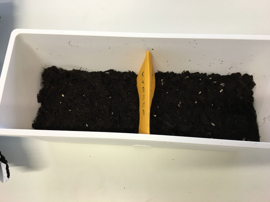
- for cress it works to distribute them on top of the surface - for others it does not
- we scale small first, if it turns out that it grows wild - then we have to go bigger
- if it turns out that cress does not work we can use sprinkles on cake (or smarties)
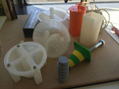
Exploration & Testing
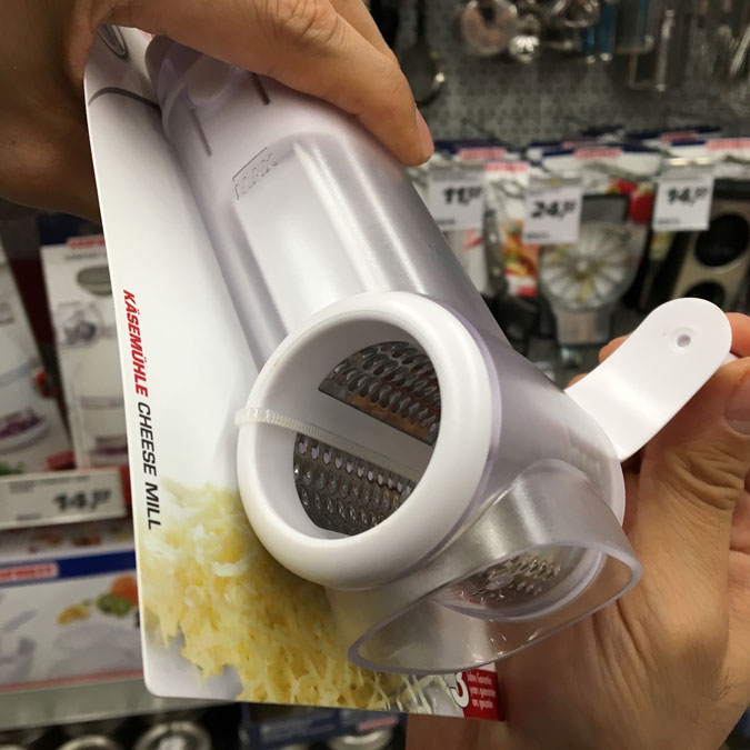
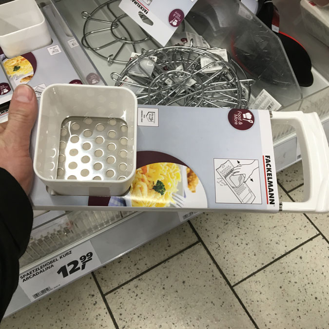
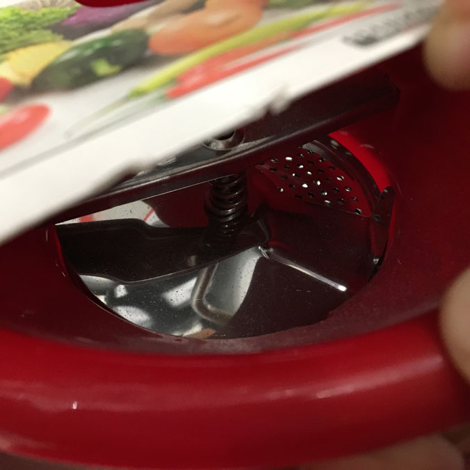
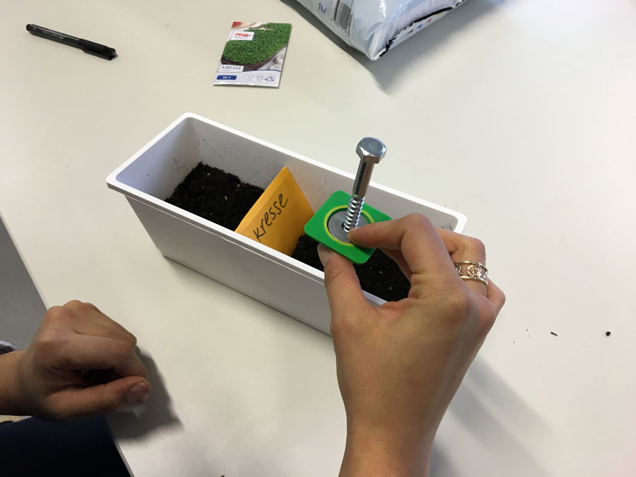
First, we went to the local supermarket and started to snoop around for mechanisms that might be useful for the extrusion of seeds.
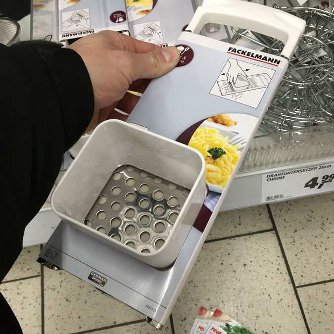


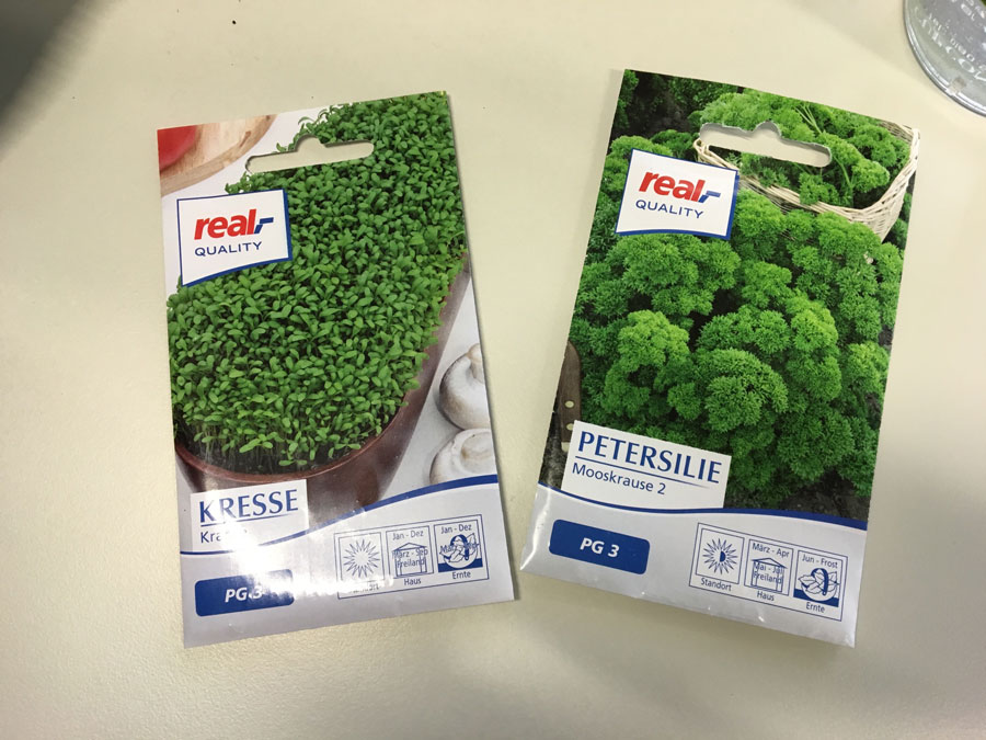
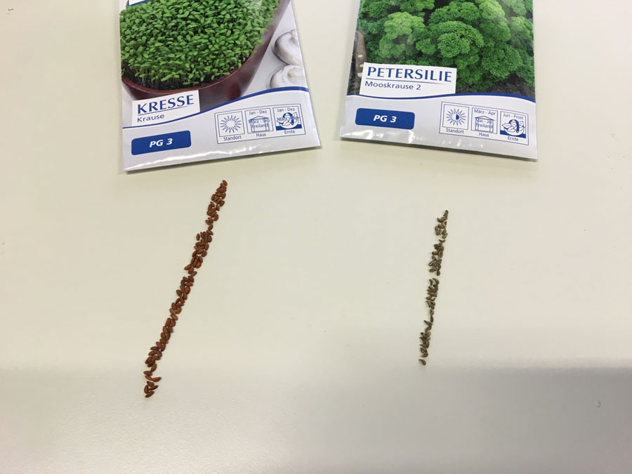
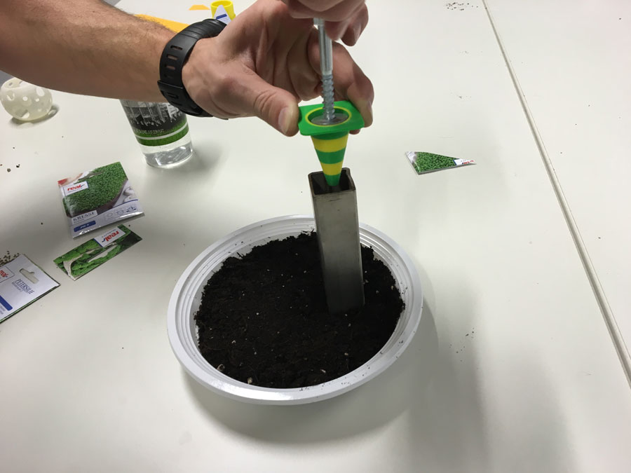
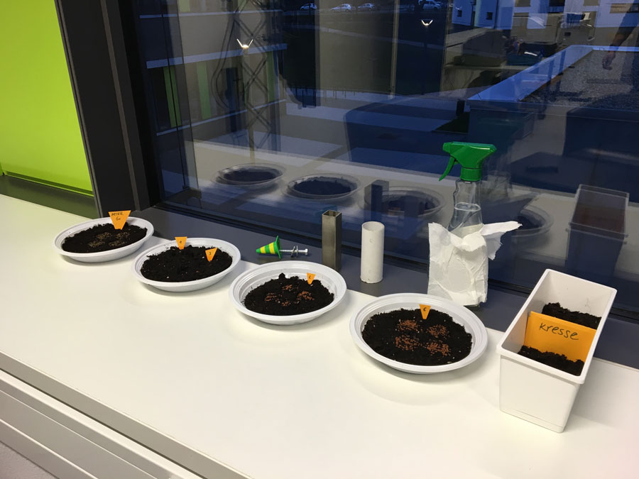
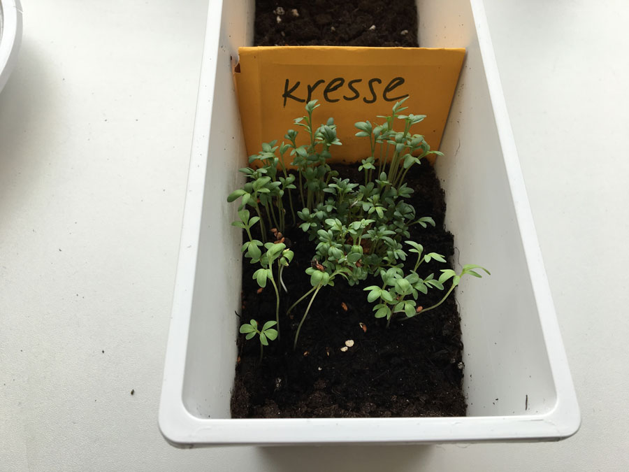
Bought cress seeds and parsley seeds ...
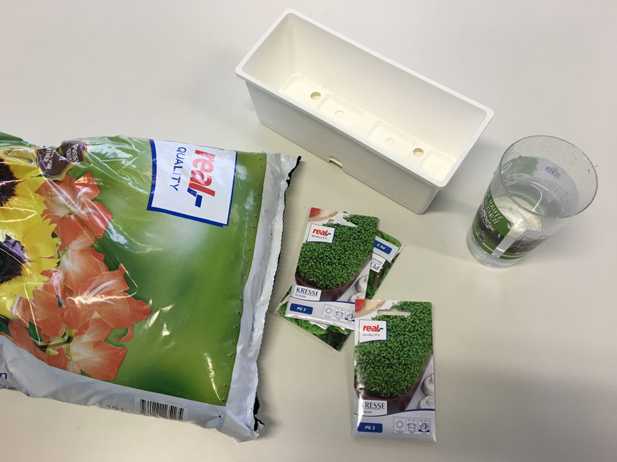
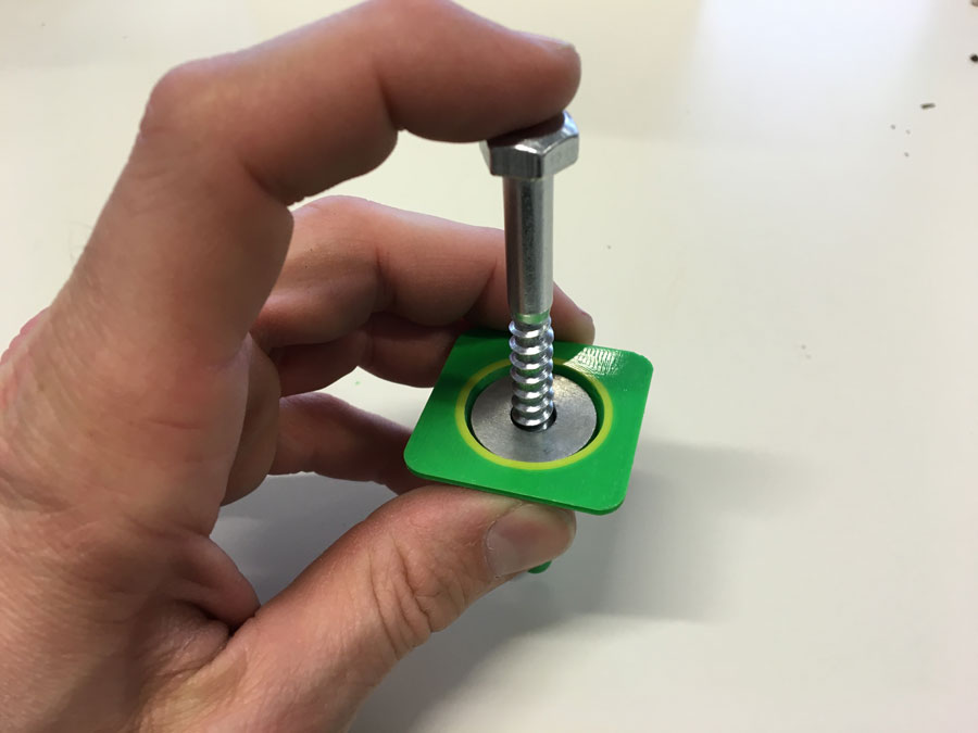
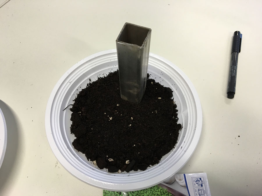
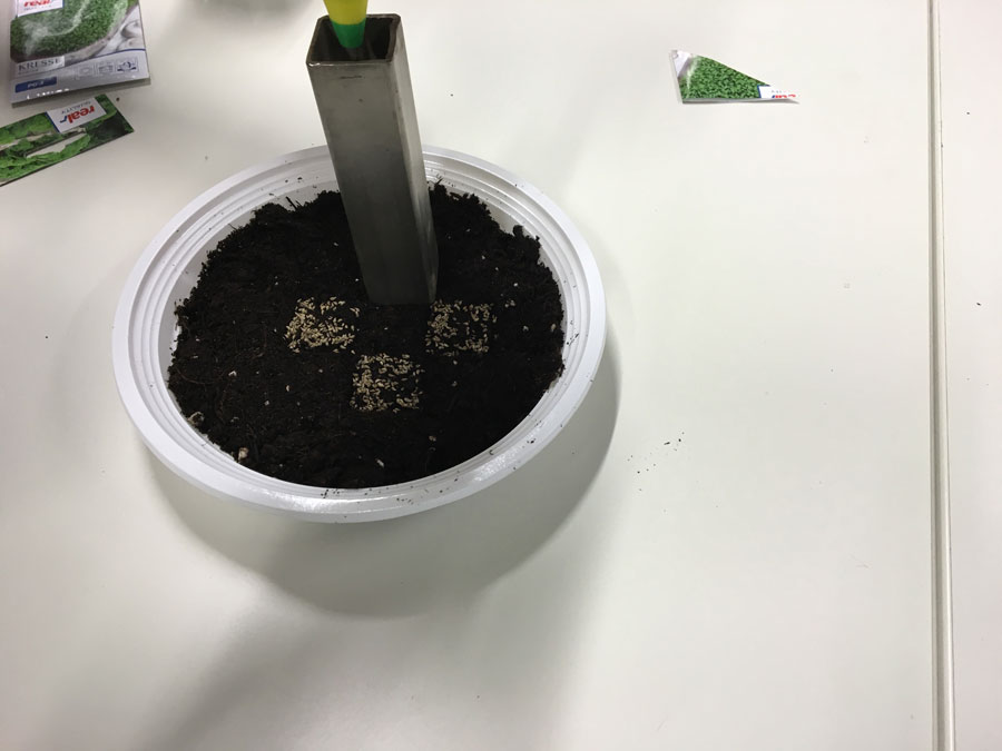
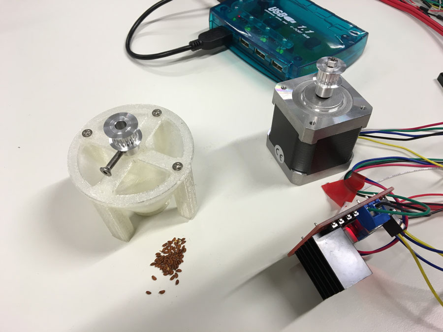
Building the seeds-extruder ... filling it ...
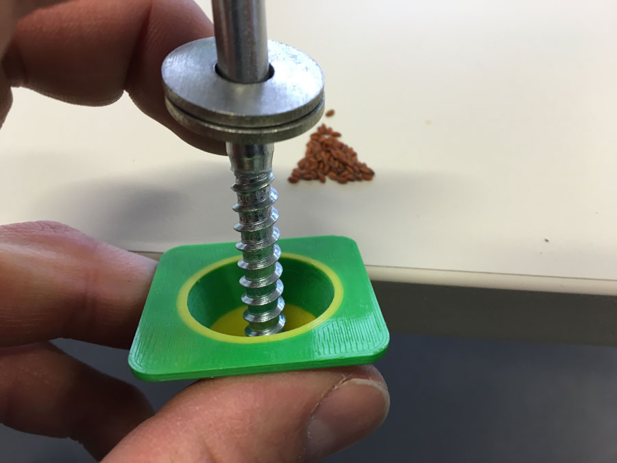
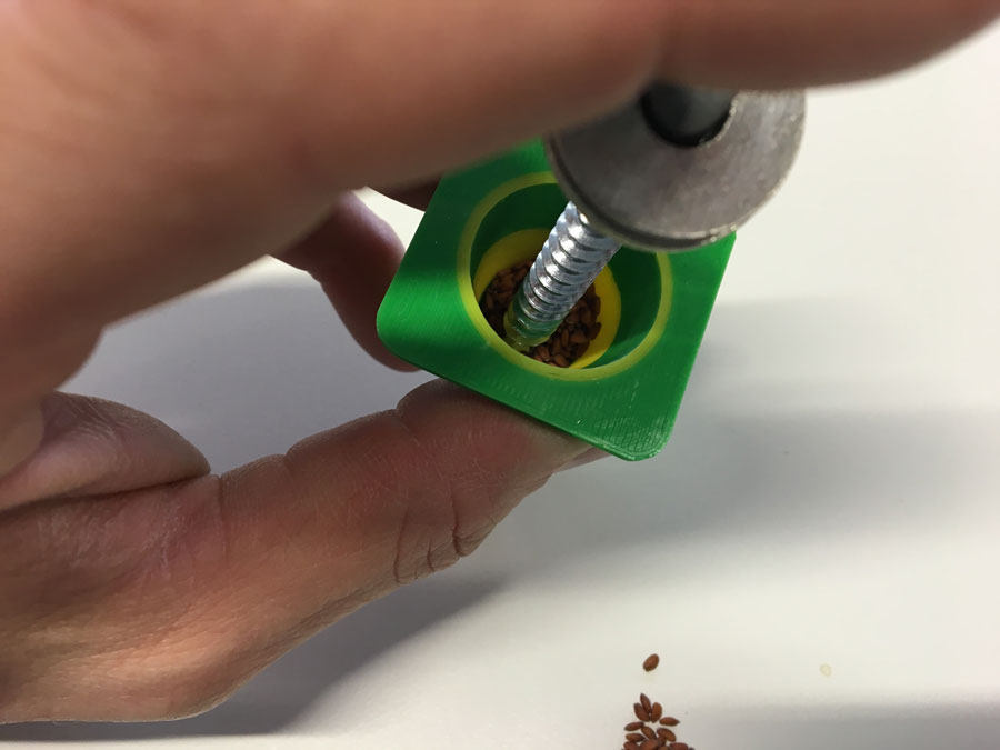
Testing the seeds-extruder ...
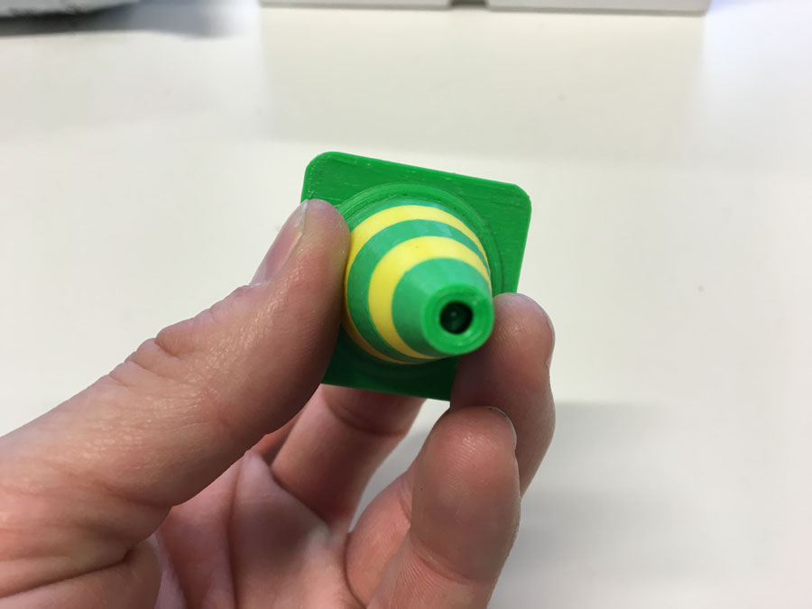
Method 1: Injection Mode
Because we wanted to have bigger pixel we thought about alternaive ways to distribute the seeds in a uniform way.
We cutted two different tubes - squared and round.
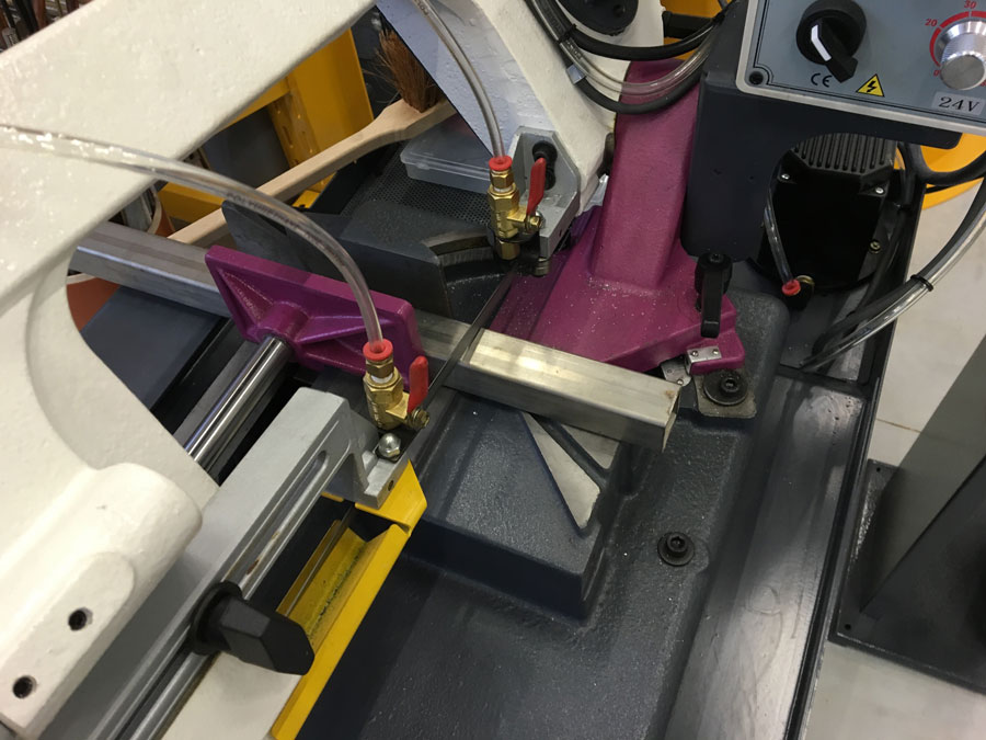
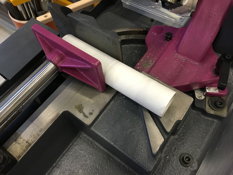
Method 2: Sprinkle (controlled) Tested the sqared one and the round one in the same way.
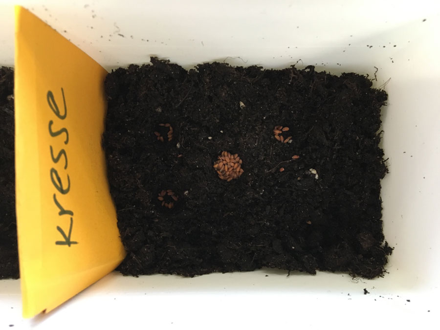
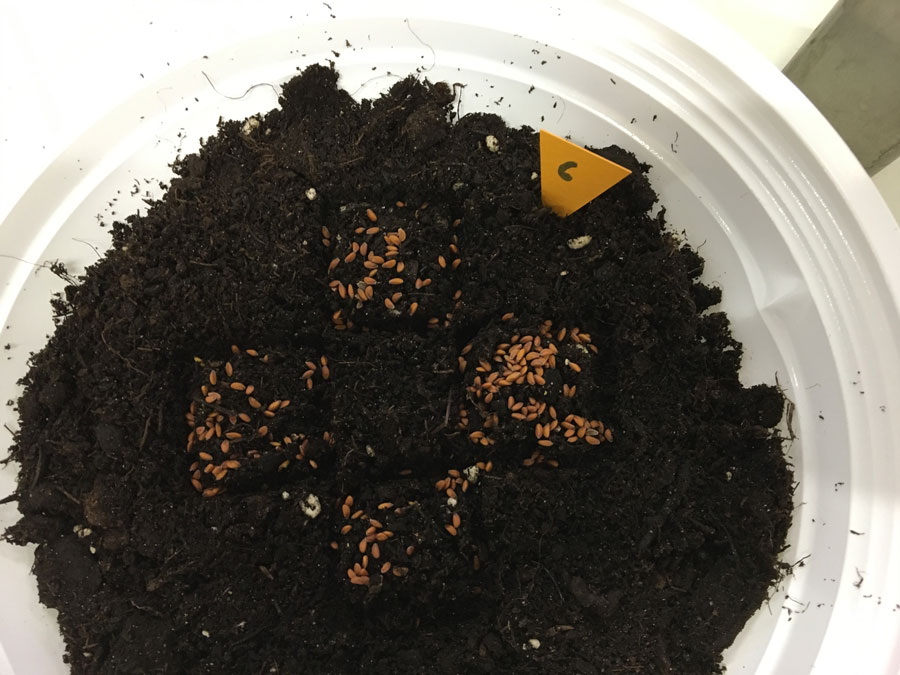
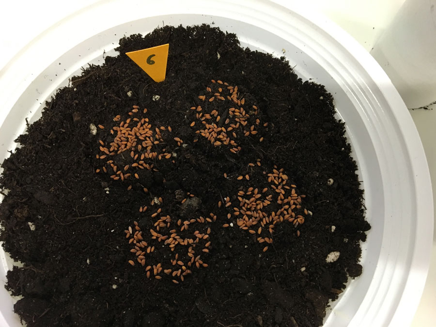
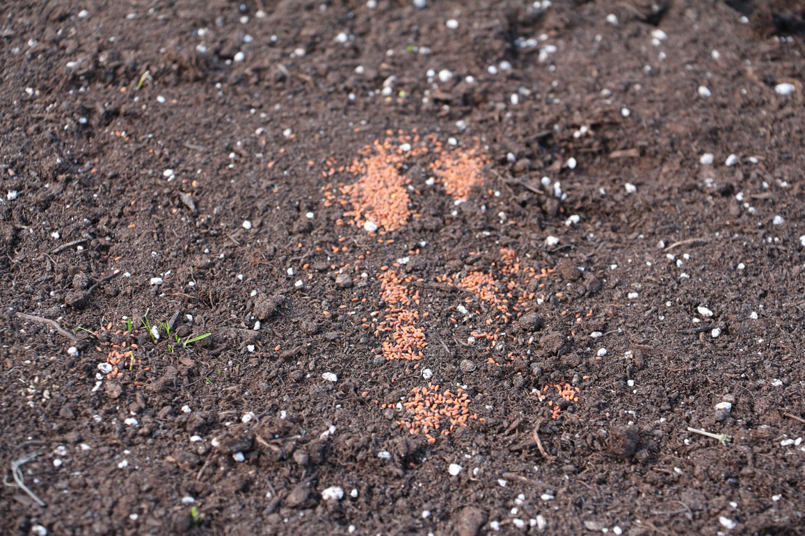
We achieved different patterns at then end, depending on the method: Injection, Sprinkle (squared), Sprinkle (round).
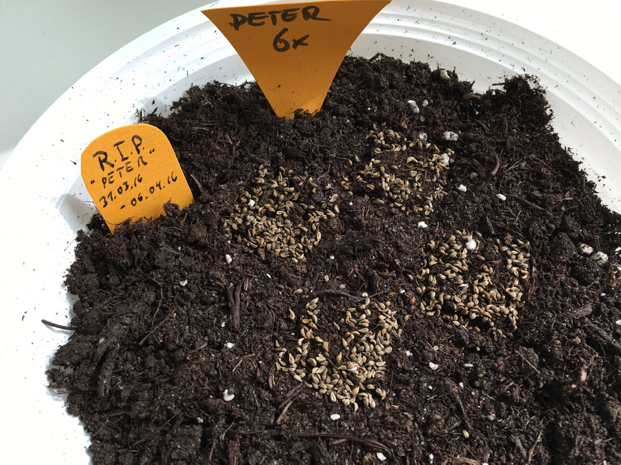
We also counted the numbers of turns (3 and 6) and noted them (little orange signs).
We also tried parsley seeds but just for reasons of visual patterns at the end. We expect the cress to grow more controlled (straight) and less bushy.
Observations
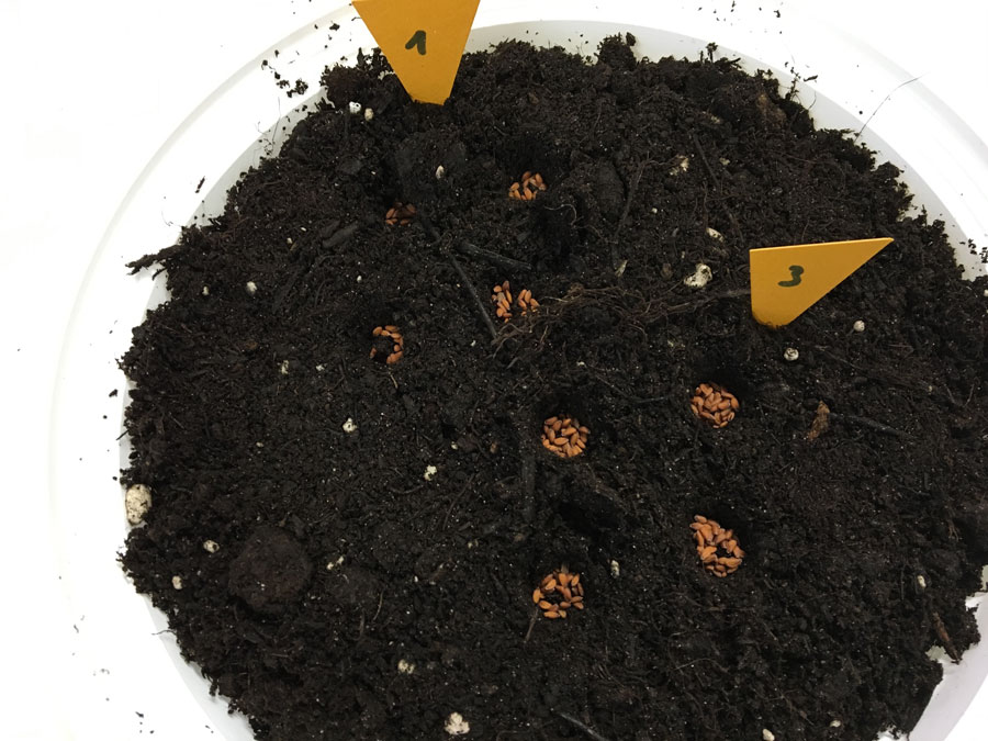
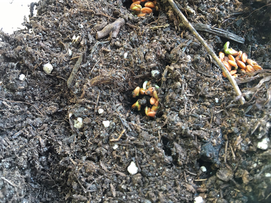
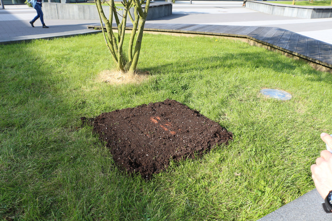
After 4 Days:
Thursday Evening, we did the tests.
There was a weekend in between and because of that, nobody could water the seeds on Sunday.
Following picture shows the results of the Insertion Mode. The other Sprinkle Methods showed no results so far
After 6 Days:
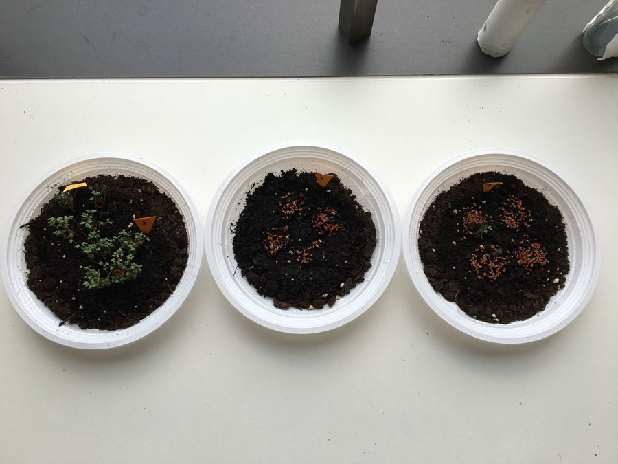
 Regrettably, "Peter" (parsley seeds = Petersilie (GER)) died :(
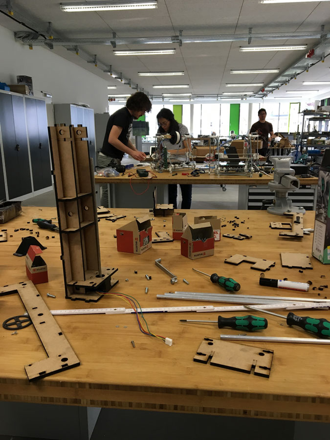
Process of MAKEing it
In principle the process of making can be separated in several phases, which of course interleave but for matter of documentation are being separated:
- Design & Construction (MTM Kit)
- Building the extruder
- FABNET USB
- "Controller" for the extruder, water supply, etc ...
- Controlling the machine (X,Y,Z)
- Controlling the extruding mechanism
- UI & image processing
- Machine Design
- Electronics
- Programming
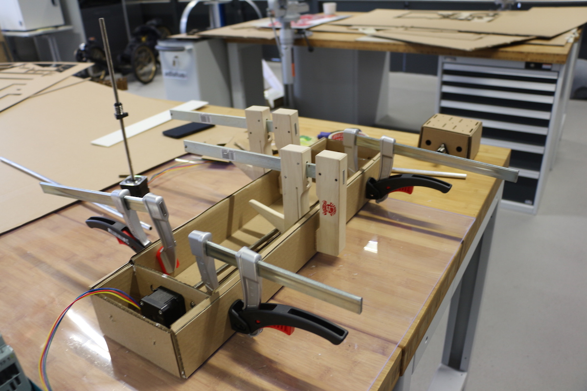
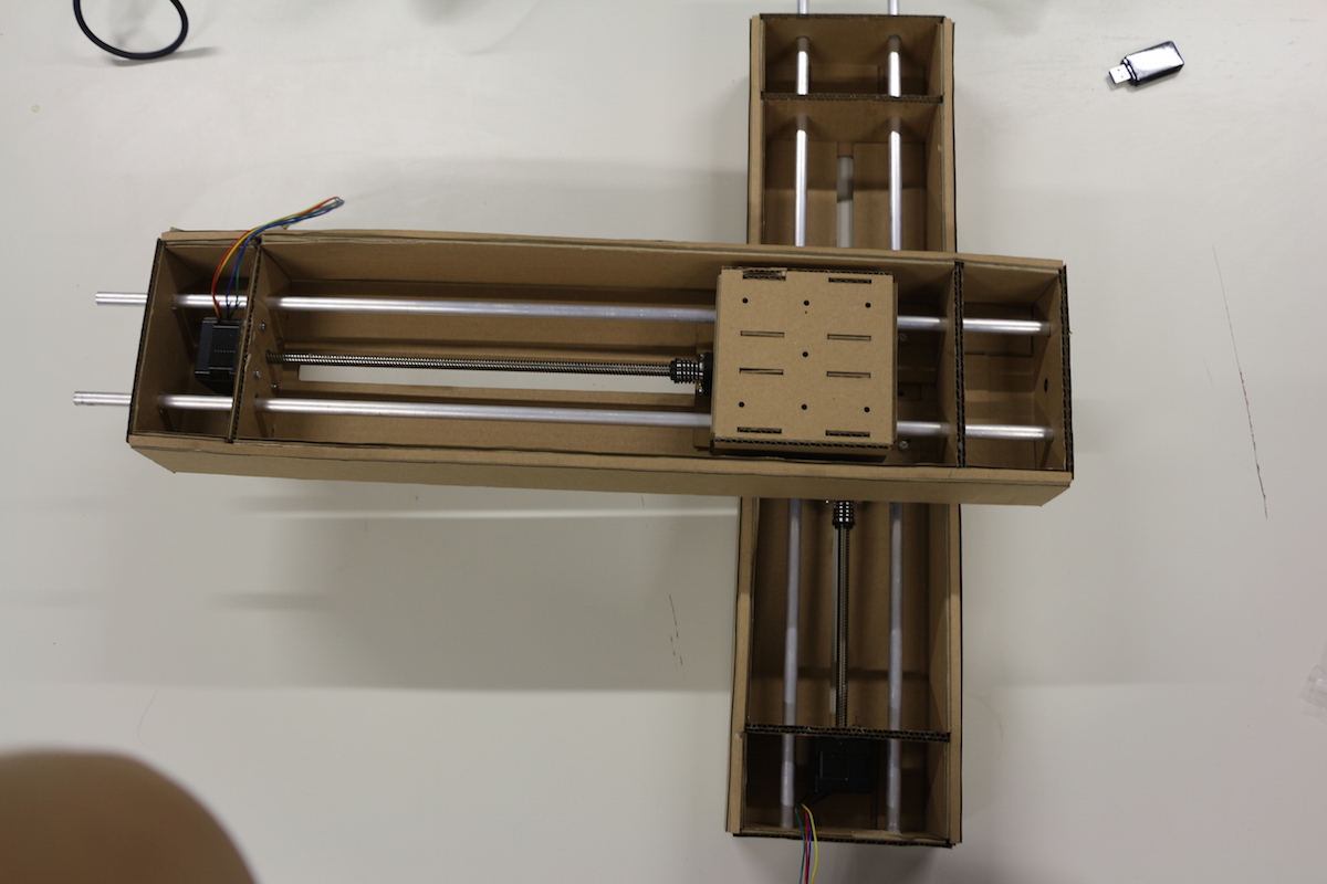
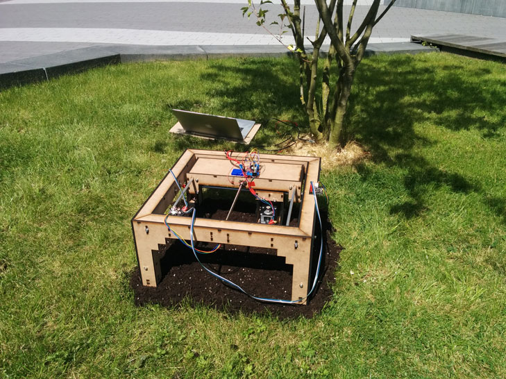
Machine Design
Design & Construction (MTM Kit)
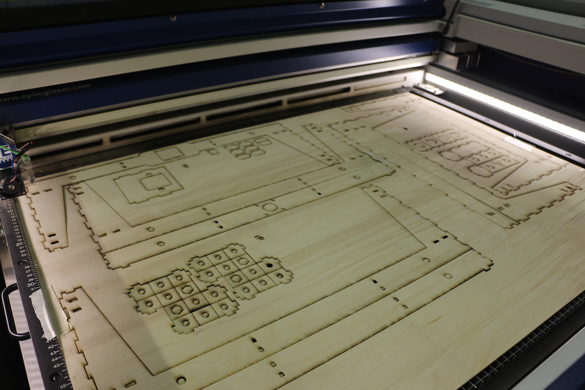
Due to the difficulties finding the 3mm conventional cardboard, I turned to another reference of cardboard: 3 mm thick Bookbinding cardboard, in grey.
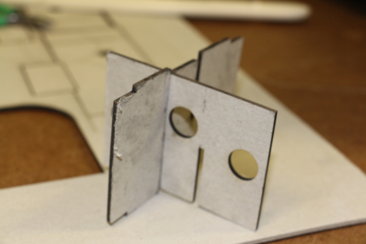
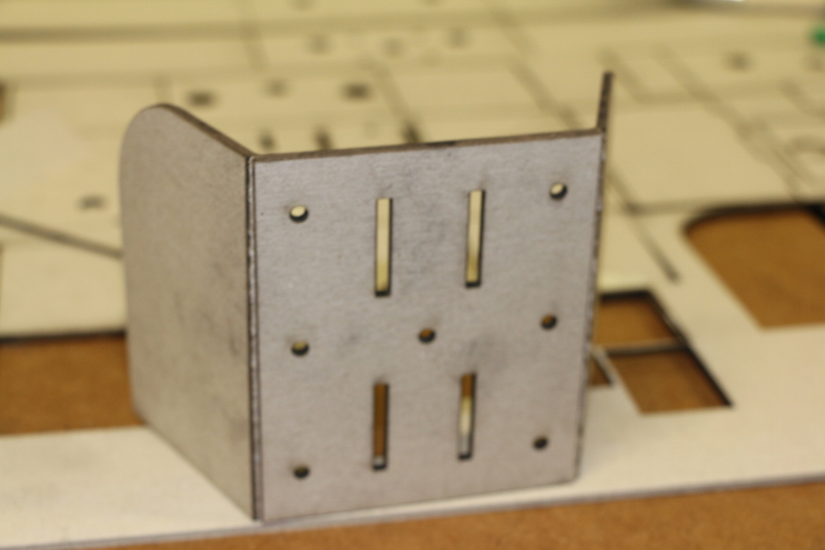
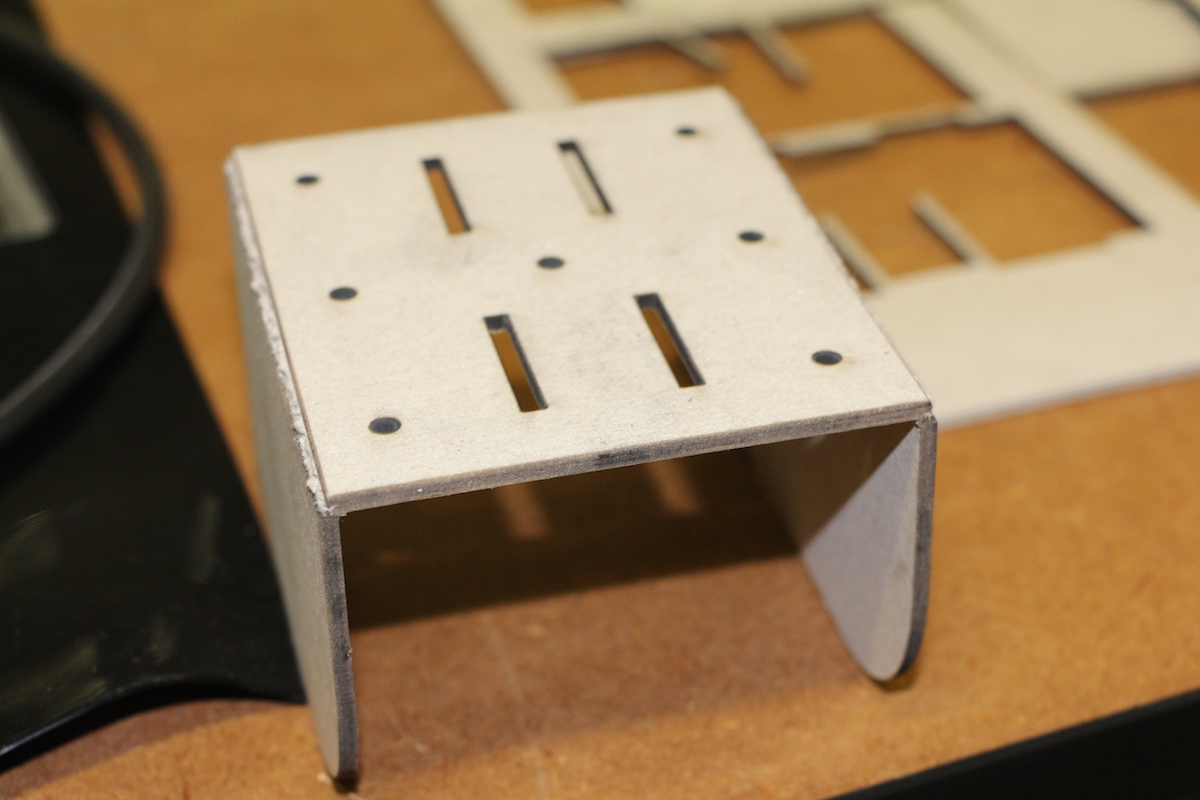
As a result, the material was bent previously, changing the cutting and engraving areas. Because hardness and thickness of the material, I couldn’t fold the cardboard as expected. Therefore, I had look for other options.
The most common cardboard that you can find in Germany is the 6 mm cardboard. Therefore, I edited the measurements of the cardboard thickness using the Rhino and Grasshopper data. In the panel of thickness, there are some modifications that you have to look before cutting but in general it doesn’t work so well, doing the folding shape.
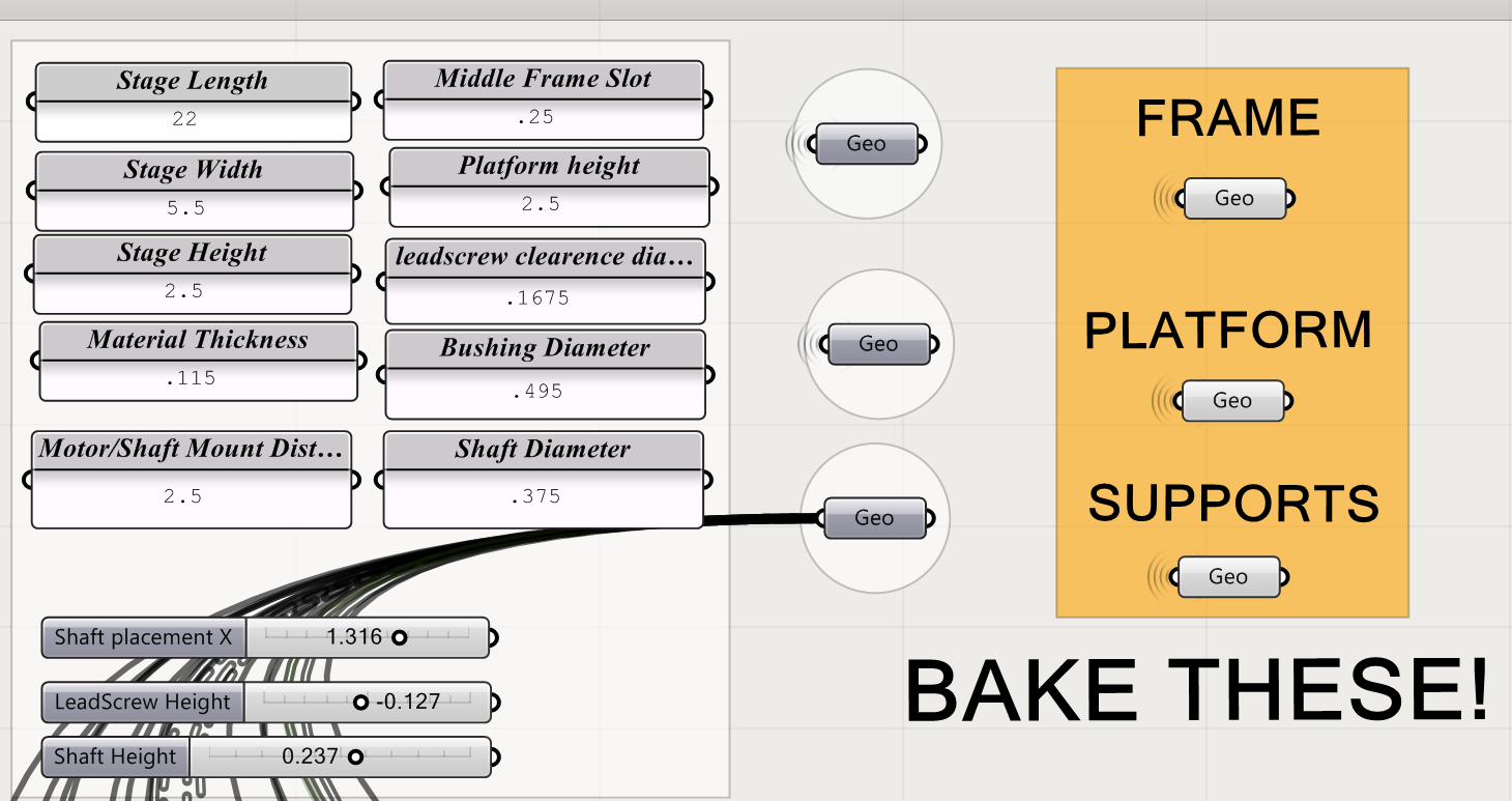
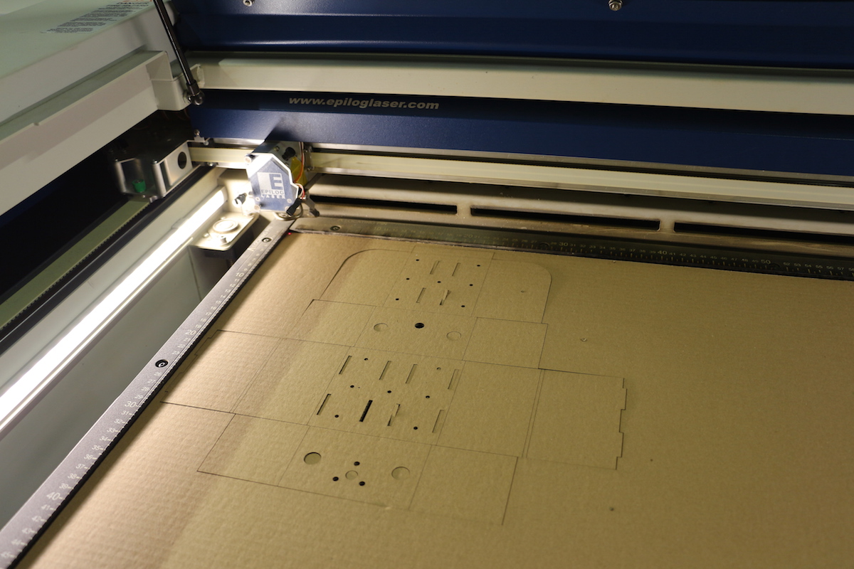
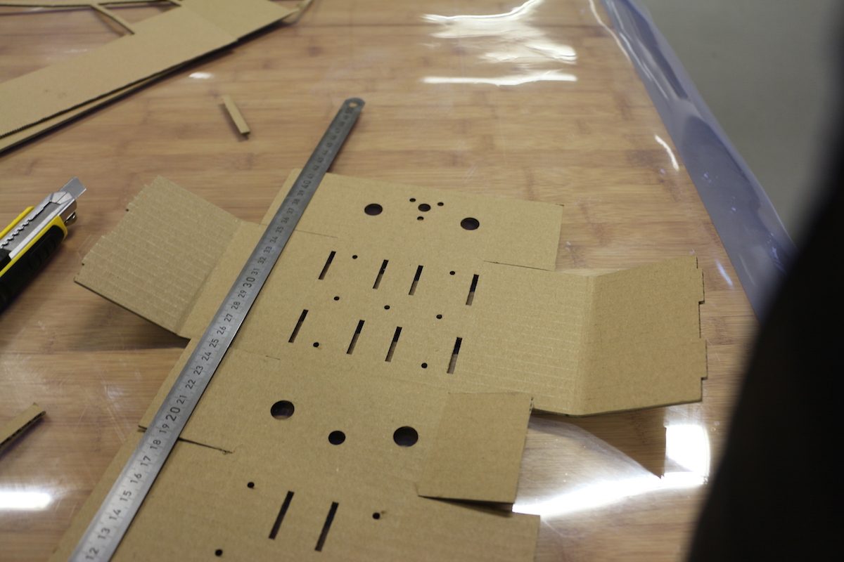
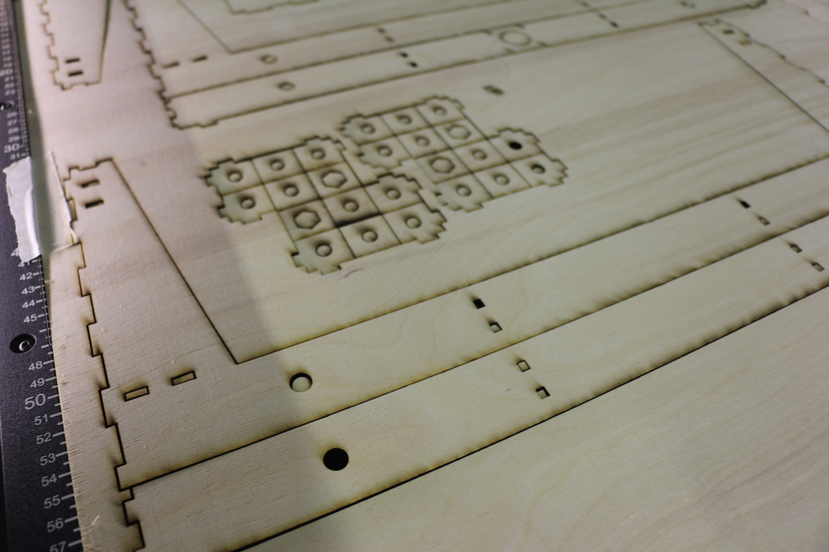
Well, I finally found the right material for cutting the gestalt node, the following steps , we cutting and assembling the cardboard parts. In the following picture you can find the cutting values for the epilog laser that we used for cutting and engraving the folding parts :
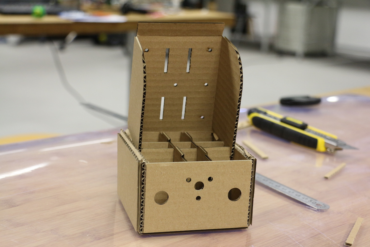
As you can see in the video, the movement of the gestalt modules axis is very reduced in comparison to the size of the pixel planter frame and the behavior at the pixels will grow. Also considering the attachment of the and weight of the extruder, we decided to change the design of the hole frame and look for other option.
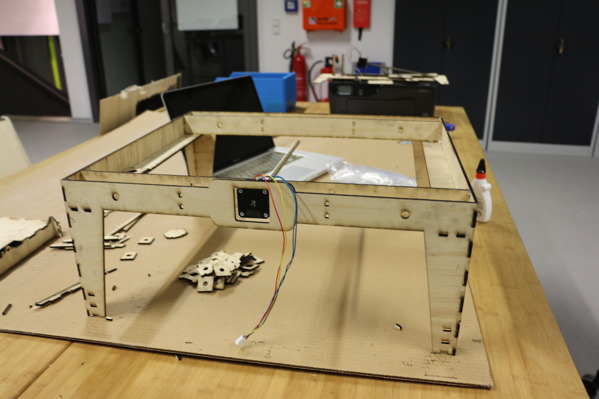
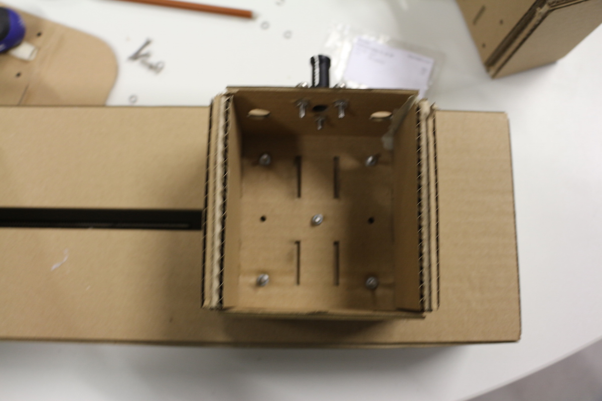
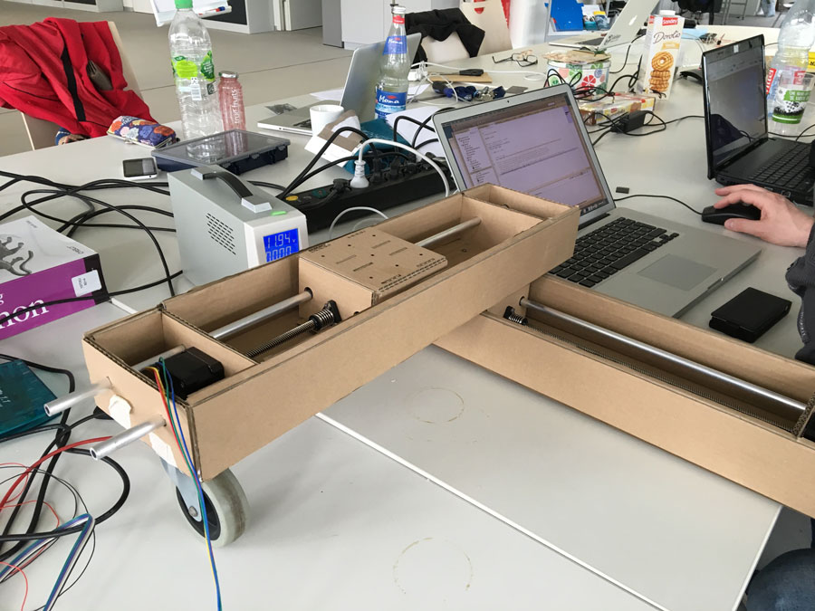
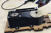
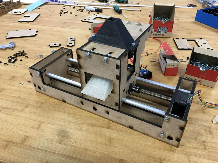
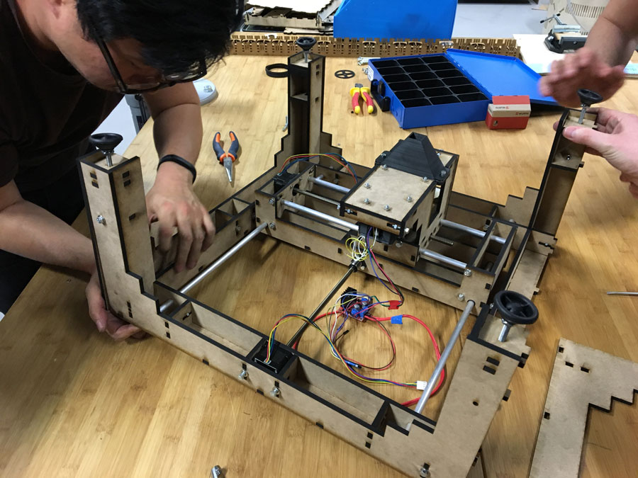
Building the Extruder, Mounting and Container (and final version of the Frame)
We also tested the SkyCam Concept:
FlyCam from usableDesign on Vimeo.
Final version of the frame:
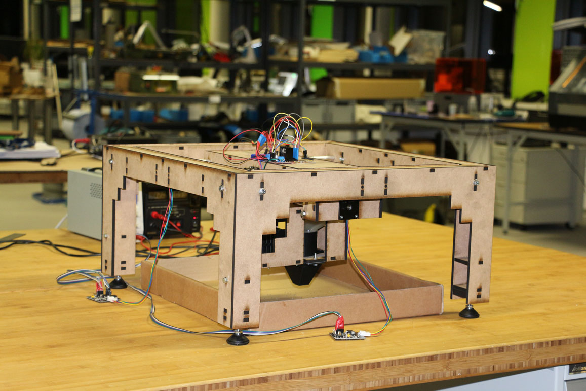
Electronics
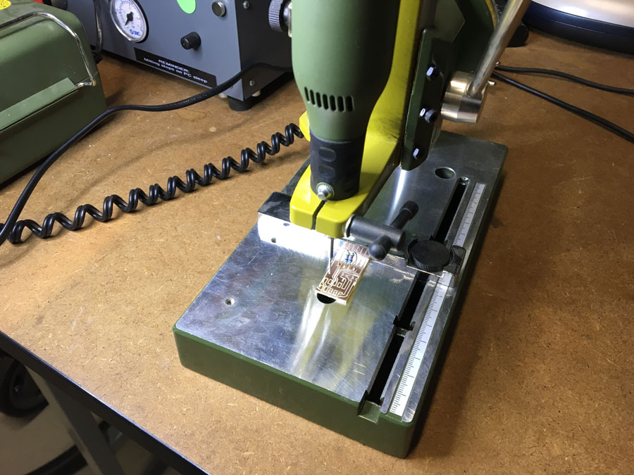
While reading through the [m]MTM website we realized that we are missing a FABNET USB:
Fabnet is a multi-drop network, meaning that multiple modules (a.k.a. nodes) share a single set of communication wires. Signalling is differential based on the RS-485 specification. Each node is assigned a four-byte IP address which uniquely identifies it over the network. Besides communication, Fabnet provides power at two voltages: high voltage (12V - 24V) is intended to drive motors, lamps and actuators, while low voltage (7.5V) supplies power to the logic circuits of the nodes.http://mtm.cba.mit.edu/fabinabox/dev/fabnet/overview.html

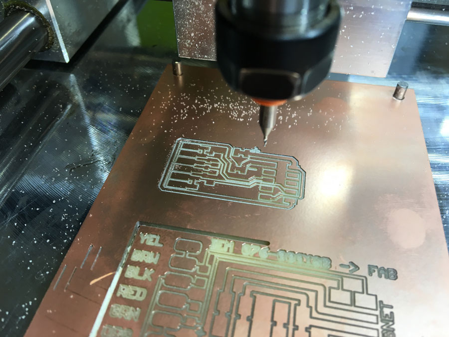
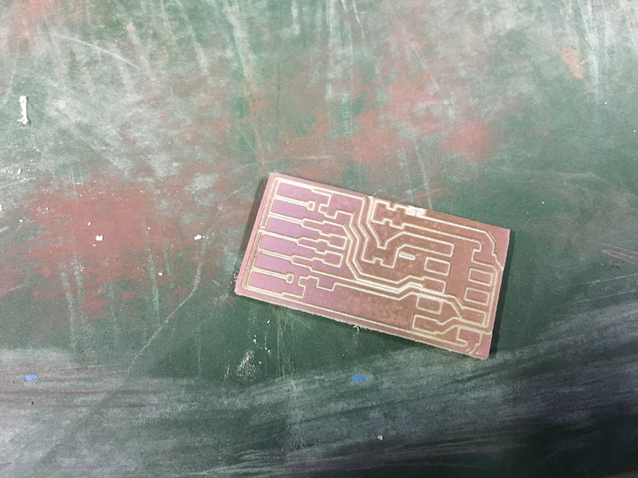
- We tried to produce the orignal FABNET USB board but for whatever reason there was a scaling issue. The Board appeared to be scaled up. Thus, we decided to use Bas's version of the board
- Here is a link to the MTM docu: Getting Started With Gestalt Nodes from the Tutorials Pages
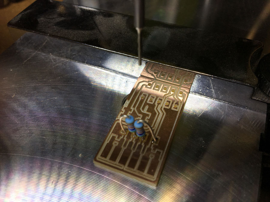
Milling the board, soldering the components, solder wires.
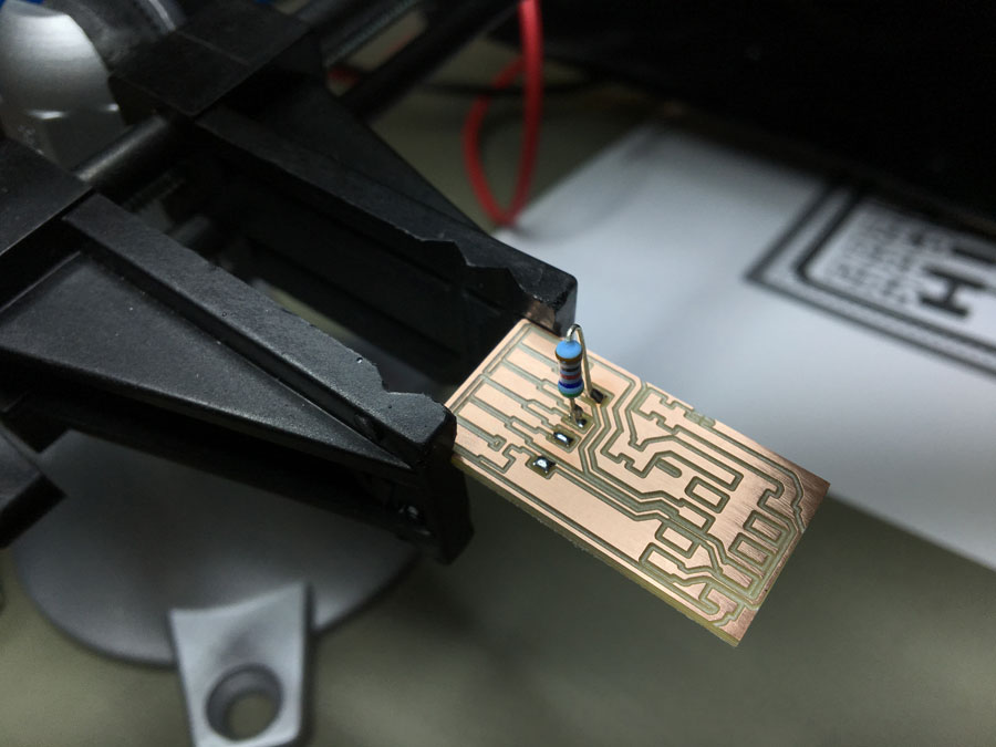
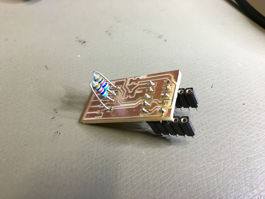
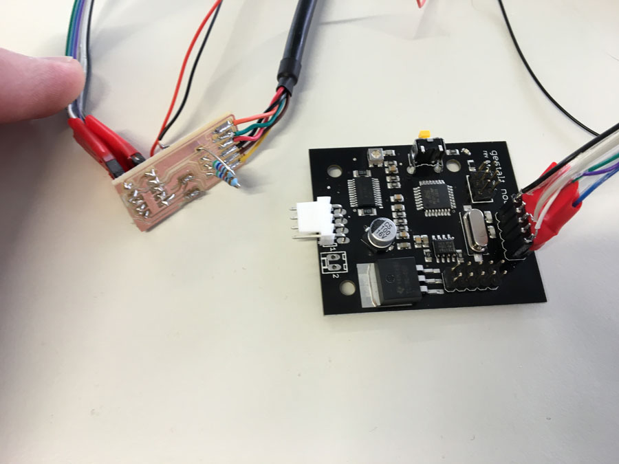
Finally, we connected the FABNET USB to the Gestalt-Node.
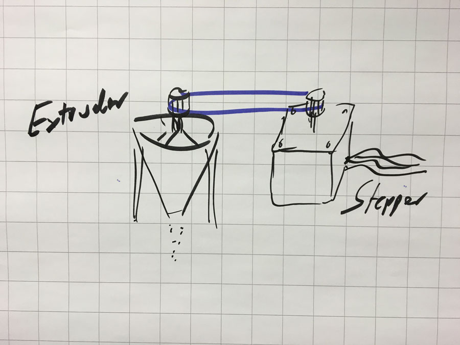
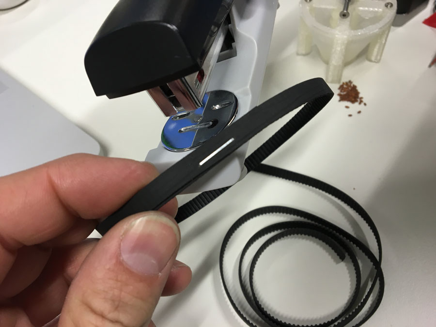
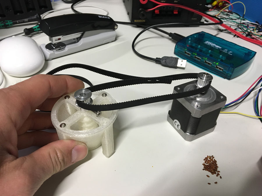
MAKE the screw-extruder turn
For the extrusion we thought about using a stepper motor (NEMA 17 Stepper motor) and a timing belt to make the screw-extruder turn.
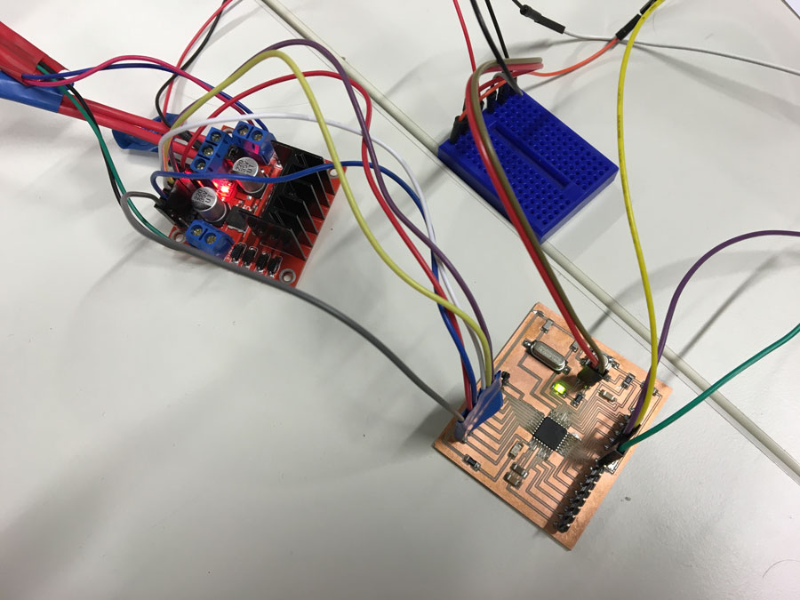
I wanted to use the L298N Dual H-Bridge Motor Controller module with an Arduino. I found some tutorails about it, such as:
- Arduino Modules - L298N Dual H-Bridge Motor Controller
- Tutorial - L298N Dual Motor Controller Module 2A and Arduino
- How to drive a Stepper Motor using Arduino and L298H Bridge
Following picture and list shows the pin-layout of the L298N H-Bridge MC.
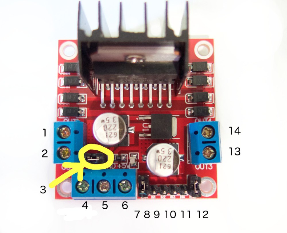
1. DC motor 1 “+” or stepper motor A+
2. DC motor 1 “-” or stepper motor A-
3. 12V jumper – remove this if using a supply voltage greater than 12V DC. This enables power to the onboard 5V regulator
4. Connect your motor supply voltage here, maximum of 35V DC. Remove 12V jumper if >12V DC
5. GND
6. 5V output if 12V jumper in place, ideal for powering your Arduino (etc)
7. DC motor 1 enable jumper. Leave this in place when using a stepper motor. Connect to PWM output for DC motor speed control.
8. IN1
9. IN2
10. IN3
11. IN4
12. DC motor 2 enable jumper. Leave this in place when using a stepper motor. Connect to PWM output for DC motor speed control.
13. DC motor 2 “+” or stepper motor B+
14. DC motor 2 “-” or stepper motor B-
The NEMA 17 comes with 6 wires. Two of them are the pairs A+ & A- and B+ and B-. Here, it is black + green and red + blue. The white and yellow ones are not used.
Connect the motor in pairs to A+ & A- and B+ and B- connectors on the L298N module. Next, connect the power supply: positive to pin 4 on the module and negative/GND to pin 5. "If you supply is up to 12V you can leave in the 12V jumper (point 3 in the image above) and 5V will be available from pin 6 on the module. This can be fed to your Arduino’s 5V pin to power it from the motors’ power supply. Don’t forget to connect Arduino GND to pin 5 on the module as well to complete the circuit." http://tronixstuff.com/2014/11/25/tutorial-l298n-dual-motor-controller-modules-and-arduino/
You need 6 digital output pins on the Arduino, of which two of them need to be PWM pins (denoted by the tilde “~”).
The Arduino digital output pins D9, D8, D7 and D6 will be connected to pins IN1, IN2, IN3 and IN4.
"The motor direction is controlled by sending a HIGH or LOW signal to the drive for each motor (or channel). For example for motor one, a HIGH to IN1 and a LOW to IN2 will cause it to turn in one direction, and a LOW and HIGH will cause it to turn in the other direction.
However the motors will not turn until a HIGH is set to the enable pin (7 for motor one, 12 for motor two). And they can be turned off with a LOW to the same pin(s). However if you need to control the speed of the motors, the PWM signal from the digital pin connected to the enable pin can take care of it" http://tronixstuff.com/2014/11/25/tutorial-l298n-dual-motor-controller-modules-and-arduino/
Here, we just use one motor, but the principle is the same.
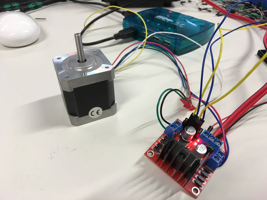
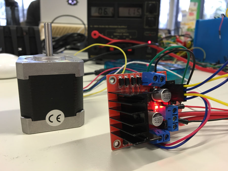
I supplied 12V to the Bridge and connected the arduino to my computer. To test it I simply used the demofile that comes with the Arduino examples: Files->Examples->Servo->Stepper Motor Control - one revolution
Finally, it works:
ScrewExtruderTest from usableDesign on Vimeo.
I wrote the code for the NAEMA Stepper motor.However, we run into some difficulties. The H-bridge (L298N DUAL FULL-BRIDGE DRIVER) ran hot.
Here is a description why: http://www.rugged-circuits.com/the-motor-driver-myth
As we want the motor to move forward and backwards continiously (for a short range of movements) so I put a delay between each movement. Because of that I thought of tunrning off the PWM pins fot that period of time. Thats why I made a simple For()-loop
for( int i=8; i<12; digitalWrite( i++, LOW ) ); in which I turned off all Pins. Well, it didn't helped.
So, I looked up the Datasheet and thought about using the two enable inputs: "Two enable inputs are provided to enable or disable the device independently of the input signals."
By doing this, I did a second trial.
/* Stepper Motor Control This program drives a unipolar or bipolar stepper motor. The motor is attached to digital pins 8 - 11 of the Arduino. The motor should revolve one revolution in one direction, then one revolution in the other direction. Modified 02.05.2016 by Karsten Nebe (based on code of by Tom Igoe) */ #includeint speed=120; int pause=500; // to prevet the H-Bridge from overheating, the motor enable pins will be manually turned off and on (when needed) int m1 = 12; // motor on/off pin int m2 = 13; // motor on/off pin const int stepsPerRevolution = 200; // change this to fit the number of steps per revolution // initialize the stepper library on pins 8 through 11: Stepper myStepper(stepsPerRevolution, 8, 9, 10, 11); void setup() { // set the speed at 60 rpm: myStepper.setSpeed(speed); // initialize the serial port: Serial.begin(9600); } void motorOn(){ // turn on motor enable pin 1 digitalWrite( m1, HIGH ); // turn on motor enable pin 2 digitalWrite( m2, HIGH ); } void motorOff(){ // turn on motor enable pin 1 digitalWrite( m1, HIGH ); // turn on motor enable pin 2 digitalWrite( m2, HIGH ); // turn off all input pins. for( int i=8; i<12; digitalWrite( i++, LOW ) ); } void loop() { // step one revolution in one direction: // Serial.println("clockwise"); motorOn(); myStepper.step(stepsPerRevolution); motorOff(); delay(pause); // step one revolution in the other direction: // Serial.println("counterclockwise"); motorOn(); myStepper.step(-stepsPerRevolution); motorOff(); delay(pause); }
Using the satshakit to run the motor of the extruder:
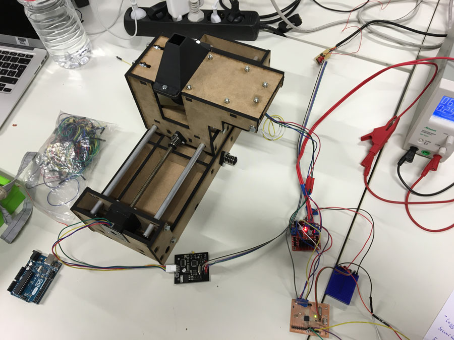
Machine Control With Gestalt Nodes and Arduino
Reading a 16x16 bitmap with Python (trivial)
For our PixelPlanter, we want to read the recipe for the machine's actions from a 16x16 pixel bitmap image. A shade between 0..255 in the image corresponds with an amount of seeds planted at the corresponding location within the bed. As simplification, we decided to use a binary image instead of a grayscale image for the final demonstration, as the result would be easier to see.
As Python does not come with an image processing library, I (Thomas) wanted to install either OpenCV for Python or the Python Imaging Library.
I first tried to install OpenCV for Python from "http://www.pyimagesearch.com/2015/06/15/install-opencv-3-0-and-python-2-7-on-osx/", but failed.
After that, I successfully installed the library PIL (Python Imaging Library). The project's homepage is here.
I used this tutorial: http://stackoverflow.com/questions/9070074/how-can-i-install-pil-on-mac-os-x-10-7-2-lion
However, before this worked, I needed to do the next:
ln -s  /Applications/Xcode.app/Contents/Developer/Platforms/MacOSX.platform/Developer/SDKs/MacOSX10.9.sdk/System/Library/Frameworks/Tk.framework/Versions/8.5/Headers/X11 /usr/local/include/X11
sudo pip install pil
xcode-select --install
The process is detailed in this tutorial: http://stackoverflow.com/questions/19532125/cant-install-pil-after-mac-os-x-10-9.
For the sake of comfort, I decided to use the Eclipse IDE and pydev from now on and to skip wxPython.
I used the following python fragment under Eclipse to read the image:
import svgParse.svg2path as svg2path
import mtm.Utils as utils
import mtm.fabMachine as plotter
from PIL import Image

if __name__ == '__main__':


    # Import an image
    img = Image.open("/Users/thomas/Desktop/FabAcademy/Week9/pixelPlanter_template.png")
    pixels = img.load() # create the pixel map

    for i in range(img.size[0]):    # for every pixel:
        for j in range(img.size[1]):
            print str(pixels[i,j])

    img.show()
...and got the following error messages from Eclipse:
Traceback (most recent call last):
  File "/Users/thomas/Documents/workspace/PixelPlanterControl/mtm/main.py", line 39, in
    pixels = img.load() # create the pixel map
  File "/Library/Python/2.7/site-packages/PIL/ImageFile.py", line 164, in load
    self.load_prepare()
  File "/Library/Python/2.7/site-packages/PIL/PngImagePlugin.py", line 381, in load_prepare
    ImageFile.ImageFile.load_prepare(self)
  File "/Library/Python/2.7/site-packages/PIL/ImageFile.py", line 231, in load_prepare
    self.im = Image.core.new(self.mode, self.size)
  File "/Library/Python/2.7/site-packages/PIL/Image.py", line 37, in __getattr__
    raise ImportError("The _imaging C module is not installed")
ImportError: The _imaging C module is not installed
The problem is due to the missing library _imaging.so, or _imagingmodule.so that belongs to the Python Imaging Library. I found more information here. I first found out whether a file named "_imaging.so" does already exist on my harddisk. Moreover, I read here that I need to add the file to "app.yaml", so I also looked for files with this name.
icds-MacBook-Pro:~ thomas$ locate _imaging.so
/Applications/Inkscape.app/Contents/Resources/lib/python2.7/site-packages/PIL/_imaging.so
/Applications/Inkscape.app/Contents/Resources/lib/python2.7/site-packages/sk1libs/imaging/_imaging.so
/Library/Python/2.7/site-packages/PIL/_imaging.so
/Users/thomas/Imaging-1.1.7/build/lib.macosx-10.11-intel-2.7/_imaging.so
icds-MacBook-Pro:~ thomas$ locate app.yaml
/Users/thomas/.p2/pool/plugins/org.python.pydev.customizations_4.5.5.201603221110/templates/google_app_engine/ask_login/app.yaml
/Users/thomas/.p2/pool/plugins/org.python.pydev.customizations_4.5.5.201603221110/templates/google_app_engine/hello_webapp_world/app.yaml
/Users/thomas/.p2/pool/plugins/org.python.pydev.customizations_4.5.5.201603221110/templates/google_app_engine/hello_world/app.yaml
icds-MacBook-Pro:~ thomas$
Our new FabLab Guru, Daniele Ingrassia, hinted me at the possibility that I am using an old version of the PIL which does potentially cause me trouble. He pointed me at the new version of the PIL that goes by the name PILLOW. I installed it with:
icds-MacBook-Pro:~ thomas$ sudo pip install pillow
Password:
The directory '/Users/thomas/Library/Caches/pip/http' or its parent directory is not owned by the current user and the cache has been disabled. Please check the permissions and owner of that directory. If executing pip with sudo, you may want sudo's -H flag.
The directory '/Users/thomas/Library/Caches/pip' or its parent directory is not owned by the current user and caching wheels has been disabled. check the permissions and owner of that directory. If executing pip with sudo, you may want sudo's -H flag.
Collecting pillow
  Downloading Pillow-3.2.0-cp27-cp27m-macosx_10_6_intel.macosx_10_9_intel.macosx_10_9_x86_64.macosx_10_10_intel.macosx_10_10_x86_64.whl (3.0MB)
    100% |████████████████████████████████| 3.0MB 355kB/s
Installing collected packages: pillow
Successfully installed pillow-3.2.0
This was the solution. With PILLOW, my modified seed of a Python Gestalt node control program worked instantaneously in Eclipse. I wrote a small function, plantImage(image, velocity) that accepts an input bitmap image and a velocity value as parameter. So far, it does nothing interesting but move to location (i, j) when value 255 is encountered within the pixel matrix. There are many things left to do: move the Z-axis, check whether the input image qualifies as a bitmap in the right dimensions, scale the coordinates in a way that they fit the bed, and so on. To be continued...
Software and hardware control of the PixelPlanter
We decided to use Ilan Moyer's Gestalt hardware and software framework as suggested in the FabAcademy class.
The Python code was developed using the PyDev plugin for Eclipse in the Eclipse IDE.
Image Processing
Our function plantImage_grayscale accepts an RGB image suitable for
the Python Imaging Library (PILLOW), converts it into real grayscale, then scales it down to size 16x16 pixels.
A pixel in the image is equivalent to a rectangular area ('box') within the bed. The higher the pixel value, the less seeds will be deployed
on the corresponding box.
Machine control strategy
The extruder head is positioned using two stepper motors, one for the x-direction, the other for the y-direction.
Each of the stepper motors is attached to a hardware Gestalt node (see photographs). The hardware Gestalt nodes are
linked serially. The first one is attached to the FabNet bridgeboard that Karsten Nebe did following this tutorial.
The FabNet bridgeboard is attached to the computer via USB.
For the software side, I have created a new Python project by the name PixelPlanterControl and imported the Gestalt libraries.
I have prepared a custom machine definition by copying and modifying the function "fabMachine.py".
The hardware Gestalt nodes are controlled by an instance of a xyNode object.
Although an xyNode can potentially steer two physical Gestalt nodes, or two stepper motors, respectively, simultaneously, I have not used this feature.
For our machine, serialized movements are adequate. Both nodes are set to the same velocity, which is among the parameters of function plantImage_grayscale.
Main function
The main function main.p is shown below.
The code for our custom software control for the PixelPlanter is imported, so is the Perl Imaging Library that is used for the basic image manipulation tasks.
The serial library needs to be imported in order to facilitate the serial communication between Arduino and the Gestalt library.
First the port to which the Arduino is attached is reserved. In below code fragment a dummy name is used. The source image is opened, and our custom function
"pixelPlanter.py" is called with the parameters path to image, velocity of the axes, box width, offsetX, offsetY.
import mtm.pixelPlanter as pixelPlanter
import serial
from PIL import Image

if __name__ == '__main__':

    # Open a serial port for communbicating with the Arduino
    arduinoCom = serial.Serial("/dev/tty.jPhone-WirelessiAP")
    img = Image.open("/Users/thomas/Desktop/FabAcademy/repository/fablabkamplintfort/students/125/week9_files/images/fabLab_logo.png")
    pixelPlanter.plantImage_grayscale(img, 7, 18, 0, 0, arduinoCom) # Arguments: path to image, velocity of the axes, box width, offsetX, offsetY
I wrote a first rendition of the function (see below screenshot) to try my hypotheses on how the library would steer the machine.
When observing the movements of the thread rods, I realized that they moved in patterns,
that were different to those I was expecting. The explanation for this was easy: I obviously had misunderstood the available documentation
of the move() command in Gestalt. Instead of using absolute coordinates as parameters for move(), I used relative coordinates.
![]()
I reworked the code (see below) to use absolute positioning. The function plantImage_grayscale() demands following arguments as input:
- image: path to RGB input image
- velocity: universally used velocity for step motors
- boxWidth: scaling factor that translates between the size of a pixel and that of a box in the bed
- offsetX: greater than zero if the bed's coordinate system is not equal to the machine's coordinate system
- offsetY: dto.
- arduinoCom: object for serial communication with an attached Arduino
Algorithm for the x-y-movement of the extruder head
The head is initially positioned at starting location (offsetX, offsetY) in the machine coordinate system. After finishing the entire planting
procedure on the whole bed, it returns to its starting location. For this location, it is convenient to place it in the middle of the upper left box.
The head moves through the bed in a meandering trajectory. It initially moves from left to right in sixteen discrete steps, then one step down, then
sixteen discrete steps from right to left, then one step down. This pattern is repeated eight times. In each discrete step, it stops in the middle of
a box. Prior to each movement, the program waits for the respective stepper motor to stop. The extent of each move is determined through the parameter boxWidth.
At each stop, the extruder stepper motor is moved as many steps as necessary to release the number of seeds that is proportional to the gray value of the
respective pixel in the source image. The functionality is outsourced to function releaseSeeds(stages, pixels[x, y], arduinoCom). The first parameter
is the base Gestalt object to represent the basic machine. The second parameter is the gray value of the pixel (x, y) in the source image which is equivalent
to the current box in the bed. The third parameter is a Serial object used for communicating with the Arduino board to which the extruder stepper motor is attached.
Initially, I had only programmed the x-y-movements of the extruder head as there was no machine yet (see Adriana's construction made of cardboard). While the number of steps the extruder head would go in any direction was fixed (15), the width of the squares on the bed was a number we needed to find empirically. We did that by first setting the parameter boxWidth in the Python code to a number that seemed suitable, then we observed whether the extruder head would cover as large a distance as possible without leaving the confines of the machine. We repeated this procedure until we found a setting for boxWidth that was acceptable.
# The bed consists of 16x16 rectangular spots ('boxes'). A spot either receives seeds, or it remains empty.
# This is controlled by the input bitmap image. A shade in the range 0..255 is equivalent to the density
# of seeds in a square within the bed. The interval is mapped onto the range 0..15, as we assume that
# one cannot distinguish more nuances in the planting.
# The parameter boxWidth is a scaling factor that maps the image coordinate system on the machine coordinate system
# A servo motor that is attached to an Arduino board is used for controlling the extruder head that emits the seeds.
# The communication between the program and the Arduino is established via serial connection.
def plantImage_grayscale(image, velocity, boxWidth, offsetX, offsetY, arduinoCom):

    imageSize = 16, 16 # The bed is divided into 16x16 boxes, so is the source image
    startX = offsetX # Initial position of the head
    startY = offsetY

    gsImage = image.convert('L') # Convert the image into a grayscale image
    thumbImage = gsImage.resize(imageSize) # Scale the image to size imageSize x imageSize
    pixels = thumbImage.load() # Create the pixel map
    thumbImage.save("/Users/thomas/Desktop/testImage.png");

    stages = virtualMachine(persistenceFile = "pixelPlanter.vmp")
    stages.xyNode.setVelocityRequest(velocity) # Universal speed for the combined node that handles x-y-plane

    # Move the head to its starting location. This is not necessarily the origin of the machine coordinate system
    # Ideally, this location lies within the middle of the leftmost box in the first row
    stages.move([startX, 0], 0)
    waitForMovementX(stages)
    stages.move([0, startY], 0)
    waitForMovementY(stages)

    # Move the head and plant the seeds
    # In each iteration, the head moves from left to right, then down, then moves from right to left
    # While the head moves in x-direction, it stops in the center of every box and releases seeds
    currentX = startX # Holds current position of the head
    currentY = startY
    for i in range(1, 8):
        # Move the head eight steps to the right in x-direction
        for step in range(1, 16):
            currentX = currentX + boxWidth
            stages.move([currentX, currentY], 0)
            waitForMovementX(stages)
            releaseSeeds(stages, pixels[step-1, 2*i-2], arduinoCom)
        # Move the head one step down in y-direction
        currentY = currentY + boxWidth
        stages.move([currentX, currentY], 0)
        waitForMovementY(stages)
        releaseSeeds(stages, pixels[step-1, 2*i-2], arduinoCom)
        # Move the head eight steps to the left in x-direction
        for step in range(1, 16):
            currentX = currentX - boxWidth
            stages.move([currentX, currentY], 0)
            waitForMovementX(stages)
            releaseSeeds(stages, pixels[step-1, 2*i-1], arduinoCom)
        # Move the head one step down in y-direction
        currentY = currentY + boxWidth
        stages.move([currentX, currentY], 0)
        waitForMovementY(stages)
        releaseSeeds(stages, pixels[step-1, 2*i-1],arduinoCom)

    # Move the head back to the starting position
    stages.move([startX, 0], 0)
    waitForMovementX(stages)
    stages.move([0, startY], 0)
    waitForMovementY(stages)
Serial communication between Arduino and Python code
For machine control, the computer is expected to control through a serial connection
a stepper motor that is linked to an Arduino Uno board. Whenever the computer sends
the shade of a pixel to the Arduino, the stepper motor shall move a number of steps
that is proportional to the shade. The exact relationship between shade and the number
of steps still needs to be decided about in an empirical study.
However, in order to make sure that a serial connection between Arduino and the Computer has
been established, a rudimentary "handshake" is made upon setting up the Arduino sketch. In
function setup(), the sketch waits for the receipt of byte 255 over the serial line (see
function waitForSerialAndReply()), then answers with byte 255. It then continues with function
loop(). There, the program keeps waiting for incoming bytes that it interprets as the shade
of a pixel. It moves the attached stepper motor that emits seeds from the extruder.
Below Arduino sketch is modified from an example by Tom Igoe. It makes use of the
stepper motor library which comes with the Arduino IDE.
/*
 * ExtruderMotorControl by Thomas Laubach

 * Modified from Tom Igoe's example sketch
 "Stepper Motor Control - one revolution"
 */

#include

int inByte = 0;
const int stepsPerRevolution = 200;  // change this to fit the number of steps per revolution

// Initialize the stepper library on pins 8 through 11
Stepper myStepper(stepsPerRevolution, 8, 9, 10, 11);

void setup()
{
  myStepper.setSpeed(60); // Set the speed of the stepper motor at 60 rpm
  Serial.begin(9600); // Start serial port at 9600 bps

  while (!waitForSerialAndReply()) {};  // Send a byte to establish contact until receiver responds
}

void loop()
{
  int shade = 0;
  int numSteps = 0; // Empirically found number of steps for our extruder, dependent on argument shade

  if (Serial.available() > 0) // Grab the next available byte from the serial line
  {
    shade = (byte) Serial.read();
    numSteps = 1.5 * shade; // TODO: find the necessary number of steps
    myStepper.step(numSteps);
    delay(500);
  }
}

boolean waitForSerialAndReply()
{
  Serial.println("Waiting for the Computer to send a 255 byte...");

  while (Serial.available() == 0) { } // Wait for a byte on the serial line

  do // Investigate the next byte from the serial line...
  {
    inByte = Serial.read();
    Serial.print("\nByte received from the Computer: ");
    Serial.print(inByte, DEC);
  }
  while (!inByte == 255); // ...as long as it is not byte 255

  Serial.println("Received a 255 from the Computer. Computer is now serially linked to Arduino board");
  Serial.write(255); // Reply with byte 255
  delay(2000);
  return true;
}
I extended the main function in Python for a basic "handshake" mechanism between the Arduino and the Computer.
The Python program first opens a serial connection to the attached Arduino Uno. Then it empties the serial input
and output buffers and waits for three seconds. After this time it sends byte 255 across the serial line in order
to tell the Arduino "that it's here". It then waits for an answer from the Arduino until it receives byte 255 on
the serial line. Only when this handshake has taken place, it opens an image file and processes it.
When the USB plug from the Arduino is plugged in, it is likely that the device name is being changed. This means that
in the program the name needs to be replaced. This is annoying and could be done automatically.
# -*- coding: utf-8 -*-

'''
Created on April 18th., 2016

@author: Thomas Laubach
'''

import mtm.pixelPlanter as pixelPlanter
import serial
from PIL import Image
from time import sleep

if __name__ == '__main__':

    # Open a serial port for communicating with the Arduino
    arduinoCom = serial.Serial("/dev/tty.usbmodemFD1321", 9600) # Speed 9600 baud
    # Send a character across the serial port in order to establish a connection to the Arduino
    arduinoCom.flushInput()
    arduinoCom.flushOutput()

    sleep(3); # Wait for three seconds
    arduinoCom.write(chr(255)) # Send a byte to the Arduino
    print "Sent byte 255 to the Arduino."

    # Wait for the Arduino to respond with another 255, then move on
    print "Now waiting for the Arduino to answer with byte 255"
    newByte = 0
    newByteStr = ""
    while newByte != 255:
        newByte = ord(arduinoCom.read()) # Read one byte from the Serial port
        if newByteStr != "":
            print "Received a new byte from the Arduino: "
            print newByte
        sleep(0.30)

    print "Received byte '255' from the Arduino. Going on..."

    # Open an image, then plant it
    img = Image.open("/Users/thomas/Desktop/FabAcademy/repository/fablabkamplintfort/students/125/week9_files/images/fabLab_logo.png")
    pixelPlanter.plantImage_grayscale(img, 7, 18, 0, 0, arduinoCom) # Arguments: path to image, velocity of the axes, box width, offsetX, offsetY
As an experiment, I have converted a FabLab logo for the PixelPlanter (see below image). For the final machine, we have simplified our approach such that it gets a halftone image, i. e. binary image, as input. Where the machine encounters a white pixel, plants are seeded, at places with a black pixel, nothing is seeded.

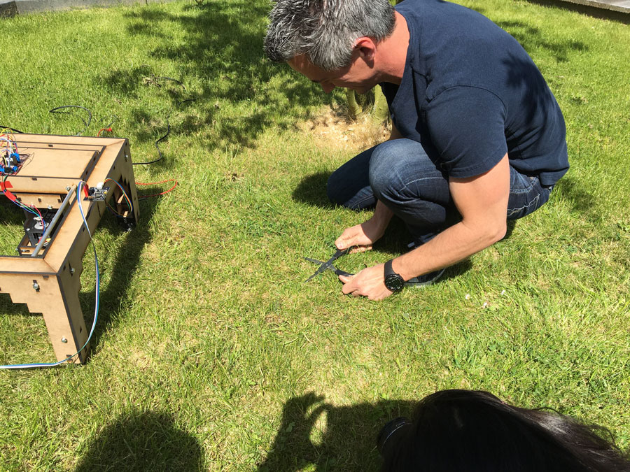
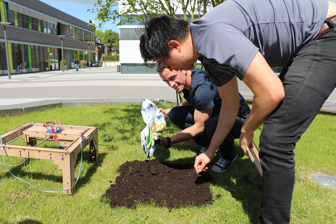
When we were testing the machine outside (see below pictures), the x-y-movements of the head were as we expected. In order to provide some time for the extruder head to release the necessary amount of seeds on a box, we inserted a short delay in the machine control code. This did not work: as the machine progressed to seed plants in the corresponding boxes on the bed, it more and more did so at the wrong spots, sometimes even planting seeds where no seeds should be planted. We assumed a synchronization problem that was due to the serial communication not working correctly, maybe because the Python serial library was buffering bytes that were read too fast. Daniele Ingrassia helped me to fix the problem. After emitting seeds, we let the Arduino code notify the Python code on the computer that it could move on to the next spot in the bed. This worked.
General remarks
- In Eclipse, you need to manually delete the persistence file before you start the program, otherwise it will throw an error. It would be convenient to make the number of seeds to be released dependent on the size of the bed. The larger the bed, the more discriminable shades are possible. We are also thinking about using seeds for differently colored plants. However, this would require a re-design of the extruder.
- The function waitForMovementX/Y(stages) is there to wait for the motors to stop spinning. As we have copied the code from the fabMachine, I have not reproduced it here.
- For this assignment, we built the Arduino-compatible Satshakit.
- Whenever the Python program is executed within the Eclipse IDE, the machine persistence file, here examples.vmp, must be deleted.
Source files
Arduino motor control sketchPython motor control Eclipse pydev project
Final Run
Downloads
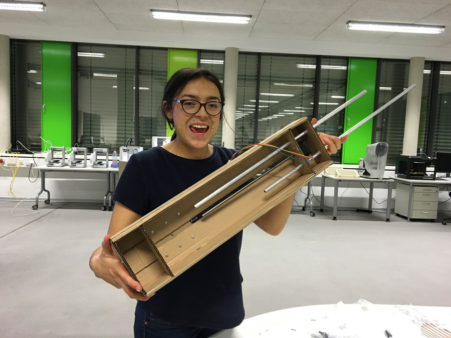
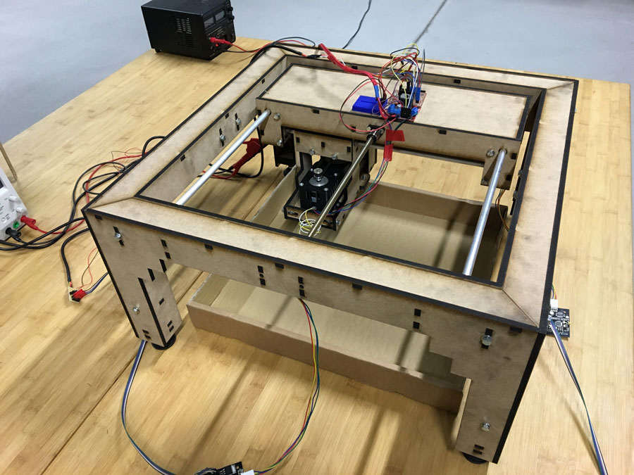
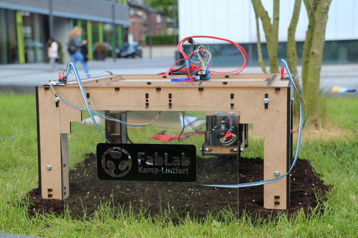
This is the final version of the frame including the extruder:
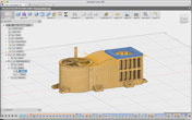
The Fusion360 File can be downloaded (here)
The python source code can be downloaded here.