Week 4: electronics production
February 17 - 23
Assignment
- Make an in-circuit programmer
Intro to EAGLE
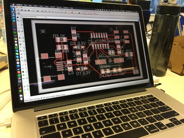
The plan for this week is to create a FabISP using a pre-made design, but also get a little bit familiar with the EAGLE user interface, as we plan to use it in a few weeks for Electronics Design. Based on this, I went with Dave's FabISP because he had the EAGLE files available.
To accomplish getting familiar with EAGLE, I took Dave's EAGLE files and made some modifications. I first added a couple of mounting holes for a planned case and followed the advice of our resident eletronic expert, Andreas, to turn the unused copper areas of the board as a unified ground. I found the interface to be extremely archaic and unintuitive. The icons are unlabled and do a very bad job of representing their functions. Despite this, I managed to slog through it and get the board to a state at which I was happy with.
Circuit Milling with CirQoid
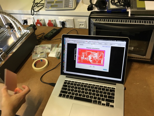
Our electronics board CNC is a CirQoid, which required a specific set of actions in order to get the files ready for its software:
1. The outer cutout shape needs to placed on Milling Layer 46. In addition, tabs should be added by removing small segments of the cutout, so the final board does not escape violently out a window into someone's eye on the completion of the milling.
2. Start the CAM processor File>CAM Processor...
3. Open the CirQoid CAM processor jobFile>Open>Job... and select cqw-gerb274x-7.2.cam and process the job
4. Next run the ULP to get the output files File>Run ULP... and select mountsmc.ulp
5. All the necessary files for CirQoid should be now in one folder
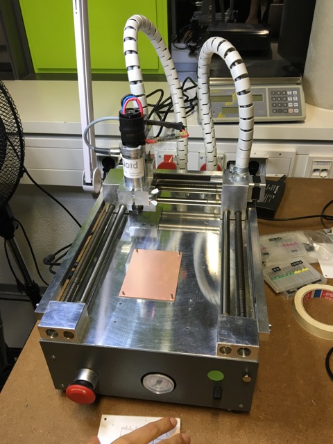
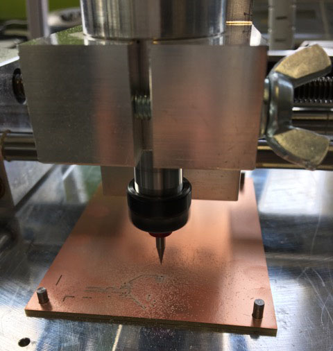
Our copper boards come without mounting holes, so these must be carefully and accurately drilled into the board before being mounted to the machine bed. Two holes must be aligned at the minimum, but at least three are preferred to ensure the board does not move during milling. So extreme care must be used during drilling.
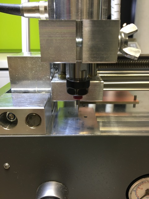
The CirQoid requires manual tool changes, and for the circuit milling, a 0.254mm 15 degree bit was selected. The software for CirQoid, cirQWizard takes you through the steps and does a scratch test in order to select the proper Z cut height.
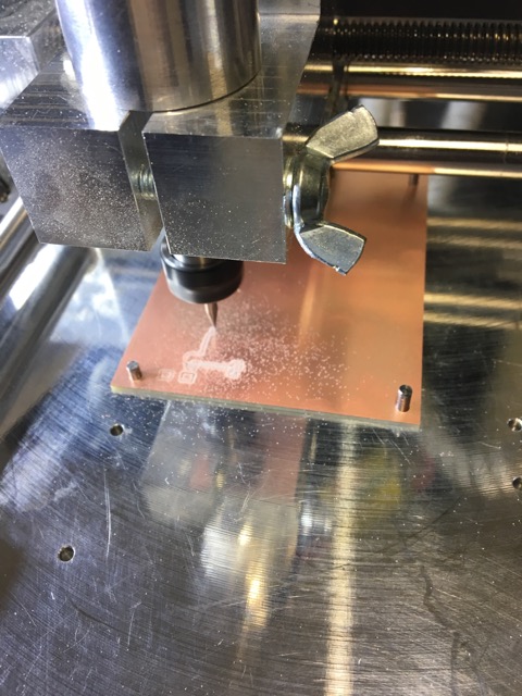
While the software isn't the most intuitive and the machine requires one to sit by with a vacuum cleaner to ensure proper extraction, the machine does its job pretty well.
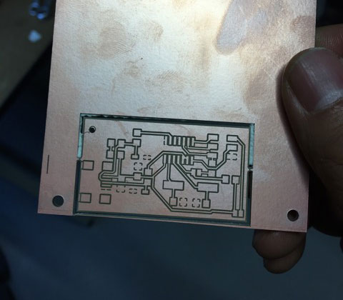
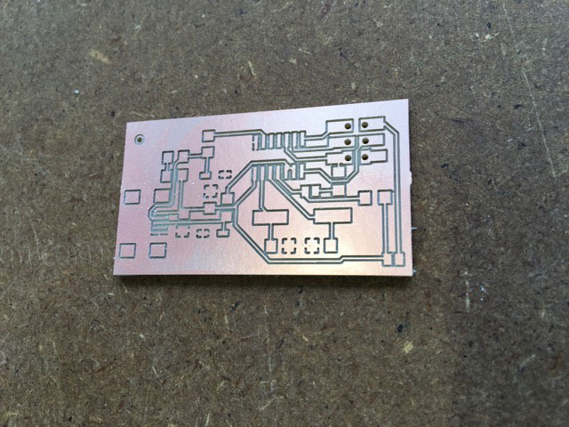
The end result is a pretty handsome board. It is washed to ensure no copper particles trapped in between the traces.
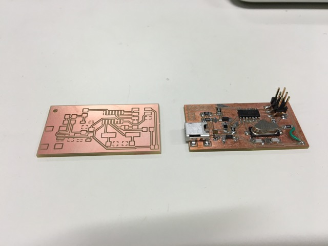
Here is a side by side comparison of before component soldering and after.
Tiny Soldering
The start of the soldering started with a couple of easier components. Having had experience in the past soldering miniscule objects, this task was not too big of a problem. The only harder part was getting the ground islands to heat up properly to accept the solder. The strategy was to tin one side first, usually the harder to reach plate, and then tack the component onto the board. Next you solder the other side and then go back and solder the tacked side.
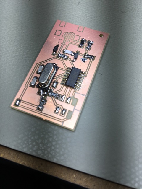
This went on until the harder components such as the micro controller and the usb plug. I used the same method of tacking one side, then I flowed solder over the entire area of contacts and used a solder wick to remove the excess.
One issue I ran into was that we had run out of 6 pin connectors, so I substituted three sets of two pin connectors. Unfortunately, the alignment wasn't the best and the copper pad ripped off the board when the serial connector was attached. I first looked for a solution to create a solder bridge for the lost pads, but it was not feasable to do so.
Restarting Anew & Troubleshooting
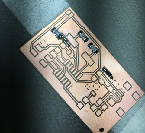
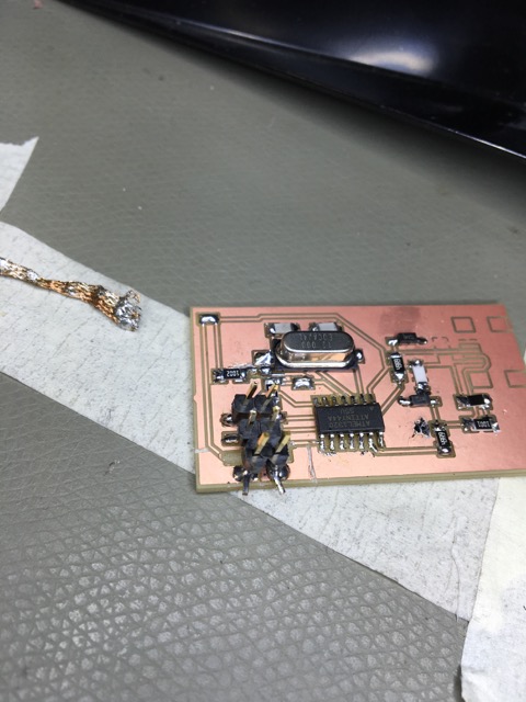
Soooo...I made another one. Someone suggested that I include 1mm holes so I can put through pins from the other side, so I did so. Great idea, right?
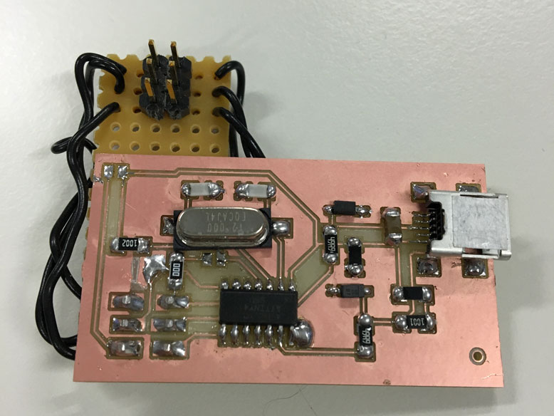
I quickly realized that putting the pins through from the other side created a mirror of the connections opposite of the serial cable connection. After many face palms I got to work on a workaround. This was the end result.
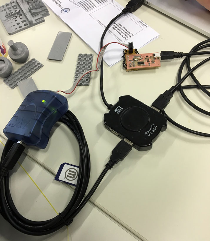
Despite its ugliness, the board worked as intended. Using Atmel's AVRISPmkii, I connected the serial cable and powered on the board with the usb cable. The programming went without a hitch, with the process documented below.
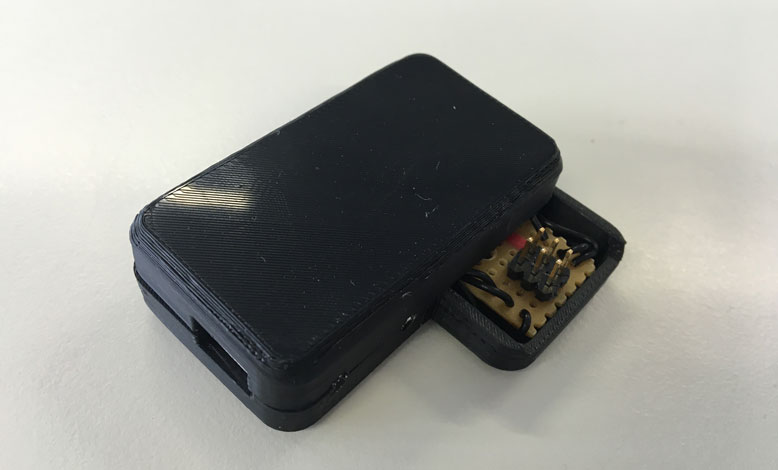
Then a case was hurriedly made to hide the majority of this monstrosity.
Programming the Board
To program the board, I turned to Atmel's AVRISPmkii device. It has a simple usb to serial connector that allows one to communicate with the on board chip. To make it compatible with the Macbook OSX, I used CrossPack for AVR® Development from Objective Development.
The programming went rather easily using the following commands:
make cleanmake hexModify the Makefile: “AVRDUDE = avrdude -c avrispmkii -P usb -p $(DEVICE)“(sudo) make fuse(sudo) make programIn the end the light blinked and the program was confirmed. Then all I had to do was disconnect the solder jumpers one and two, and the programmer was ready for use.
$ make hex
avr-gcc -Wall -Os -DF_CPU=12000000
-Iusbdrv -I. -DDEBUG_LEVEL=0 -mmcu=attiny44 -c usbdrv/usbdrv.c -o usbdrv/usbdrv.o
avr-gcc -Wall -Os -DF_CPU=12000000
-Iusbdrv -I. -DDEBUG_LEVEL=0 -mmcu=attiny44 -x assembler-with-cpp -c usbdrv/usbdrvasm.S -o usbdrv/usbdrvasm.o
avr-gcc -Wall -Os -DF_CPU=12000000
-Iusbdrv -I. -DDEBUG_LEVEL=0 -mmcu=attiny44 -c usbdrv/oddebug.c -o usbdrv/oddebug.o
avr-gcc -Wall -Os -DF_CPU=12000000
-Iusbdrv -I. -DDEBUG_LEVEL=0 -mmcu=attiny44 -c main.c -o main.o
main.c:88:13: warning: always_inline function might not be inlinable [-Wattributes]
 static void delay ( void )
             ^
avr-gcc -Wall -Os -DF_CPU=12000000
-Iusbdrv -I. -DDEBUG_LEVEL=0 -mmcu=attiny44 -o main.elf usbdrv/usbdrv.o usbdrv/usbdrvasm.o usbdrv/oddebug.o main.o
rm -f main.hex main.eep.hex
avr-objcopy -j .text -j .data -O ihex main.elf main.hex
avr-size main.hex
   text   data
    bss     dec
    hex filename
      0   2070
      0   2070
    816 main.hex
jy ~/Documents/FabAcademy/Training (intern)/Embedded programming/fabISP_mac.0.8.2_firmware $ make fuse
avrdude -c avrispmkii -P usb -p attiny44  -U hfuse:w:0xDF:m -U lfuse:w:0xFF:m

avrdude: AVR device initialized and ready to accept instructions

Reading | ################################################## | 100% 0.00s

avrdude: Device signature = 0x1e9207
avrdude: reading input file "0xDF"
avrdude: writing hfuse (1 bytes):

Writing | ################################################## | 100% 0.00s

avrdude: 1 bytes of hfuse written
avrdude: verifying hfuse memory against 0xDF:
avrdude: load data hfuse data from input file 0xDF:
avrdude: input file 0xDF contains 1 bytes
avrdude: reading on-chip hfuse data:

Reading | ################################################## | 100% 0.00s

avrdude: verifying ...
avrdude: 1 bytes of hfuse verified
avrdude: reading input file "0xFF"
avrdude: writing lfuse (1 bytes):

Writing | ################################################## | 100% 0.00s

avrdude: 1 bytes of lfuse written
avrdude: verifying lfuse memory against 0xFF:
avrdude: load data lfuse data from input file 0xFF:
avrdude: input file 0xFF contains 1 bytes
avrdude: reading on-chip lfuse data:

Reading | ################################################## | 100% 0.00s

avrdude: verifying ...
avrdude: 1 bytes of lfuse verified

avrdude: safemode: Verify error - unable to read hfuse properly. Programmer may not be reliable.
avrdude: safemode: Fuses OK (H:FF, E:DF, L:FF)

avrdude done.  Thank you.

jy ~/Documents/FabAcademy/Training (intern)/Embedded programming/fabISP_mac.0.8.2_firmware $ make program
avrdude -c avrispmkii -P usb -p attiny44  -U flash:w:main.hex:i

avrdude: AVR device initialized and ready to accept instructions

Reading | ################################################## | 100% 0.00s

avrdude: Device signature = 0x1e9207
avrdude: NOTE: "flash" memory has been specified, an erase cycle will be performed
         To disable this feature, specify the -D option.
avrdude: erasing chip
avrdude: reading input file "main.hex"
avrdude: writing flash (2070 bytes):

Writing | ################################################## | 100% 0.72s

avrdude: 2070 bytes of flash written
avrdude: verifying flash memory against main.hex:
avrdude: load data flash data from input file main.hex:
avrdude: input file main.hex contains 2070 bytes
avrdude: reading on-chip flash data:

Reading | ################################################## | 100% 0.65s

avrdude: verifying ...
avrdude: 2070 bytes of flash verified

avrdude: safemode: Fuses OK (H:FF, E:DF, L:FF)

avrdude done.  Thank you.

avrdude -c avrispmkii -P usb -p attiny44  -U hfuse:w:0xDF:m -U lfuse:w:0xFF:m

avrdude: AVR device initialized and ready to accept instructions

Reading | ################################################## | 100% 0.00s

avrdude: Device signature = 0x1e9207
avrdude: reading input file "0xDF"
avrdude: writing hfuse (1 bytes):

Writing | ################################################## | 100% 0.00s

avrdude: 1 bytes of hfuse written
avrdude: verifying hfuse memory against 0xDF:
avrdude: load data hfuse data from input file 0xDF:
avrdude: input file 0xDF contains 1 bytes
avrdude: reading on-chip hfuse data:

Reading | ################################################## | 100% 0.00s

avrdude: verifying ...
avrdude: 1 bytes of hfuse verified
avrdude: reading input file "0xFF"
avrdude: writing lfuse (1 bytes):

Writing | ################################################## | 100% 0.00s

avrdude: 1 bytes of lfuse written
avrdude: verifying lfuse memory against 0xFF:
avrdude: load data lfuse data from input file 0xFF:
avrdude: input file 0xFF contains 1 bytes
avrdude: reading on-chip lfuse data:

Reading | ################################################## | 100% 0.00s

avrdude: verifying ...
avrdude: 1 bytes of lfuse verified

avrdude: safemode: Fuses OK (H:FF, E:DF, L:FF)

avrdude done.  Thank you.