Assignment 4 - Week4 - Electronics Production
This assignment talks about PCB fabrication , and my reference was that LINK.
The FabISP is an in-system programmer for AVR microcontrollers, designed for production within a FabLab. That is, it allows you to program the microcontrollers on other boards you make, using nothing but a USB cable and 6-pin IDC to 6-pin IDC cable. It's based on the USBtiny and V-USB firmwares, which allow the ATtiny44 to perform USB communication in software. Programming can be done through avrdude. The schematic (PDF) is super simple: USB connector, ATtiny44, and 6-pin ISP header, with assorted passive components. I started with the Eagle files for the USBtinyISP, although there's almost nothing left of it. Most of the parts for the FabISP are in the FabLab inventory. Exceptions include the Mini-B USB connector (SparkFun, Digi-Key), 12 MHz crystal (Digi-Key), and 18 pF capacitors for the crystal (Digi-Key).
I saw fabisp tool before many times , i saw in my opinion a design fault , maybe it's right and maybe it's wrong ,but my target is to make smaller in width so that i can put a heat shrink around it to make more handy , also i want to increase the thickness of the copper tracks and put some LEDs ,one for power and another for serial clicks as an indicator for programming progress.
First: studying - Second
I studied david's circuit well and searched the internet and found that usb devices must have 12mHz crystal , and david has done that.
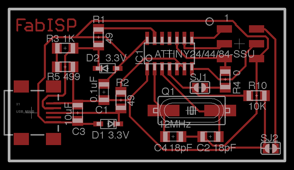
Here is his board layout.
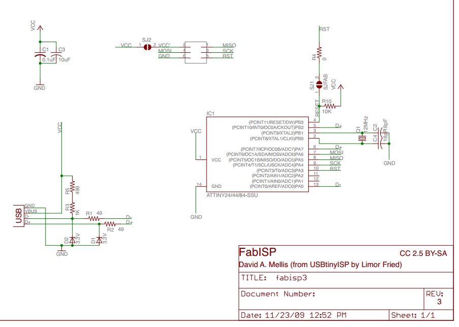
And here is his circuit.
Second: - First
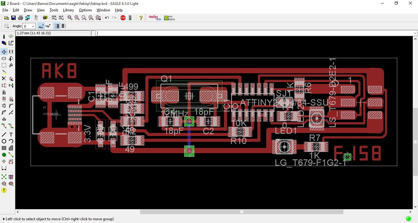
My own design in CadSoft EAGLE PCB Design Software.
Here is the PNG file.
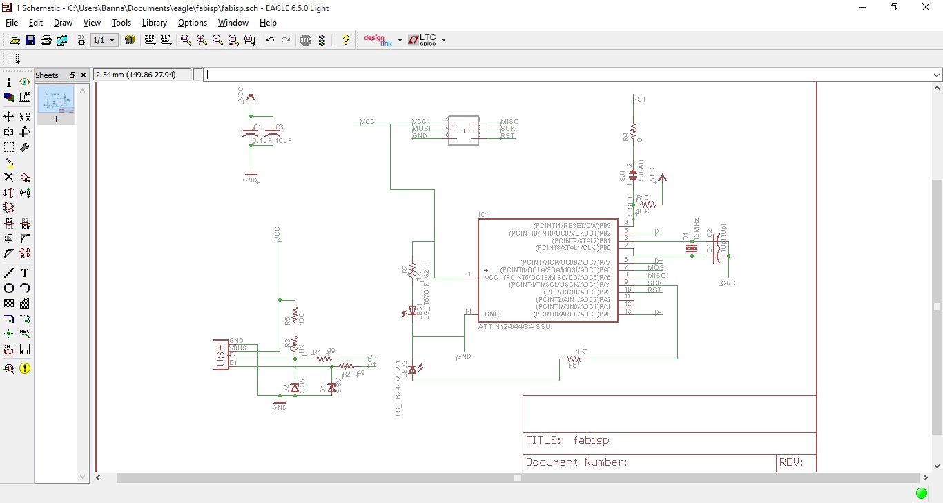
After switching from schematic design to board design.
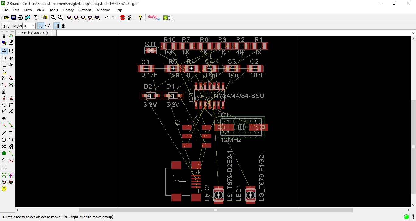
And here is after arranging the components.
Hardware Interface
The board connects to the computer using a Mini USB cable. It connects to the target (the board being programmed) with an 6-pin cable on the 2x3 ISP header.
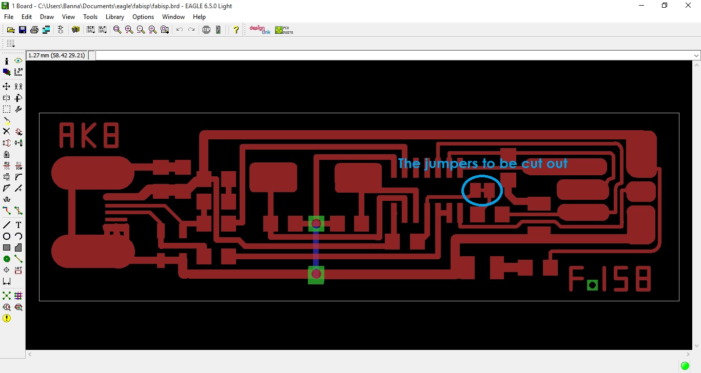
The FabISP board contains one solder jumpers: pairs of adjacent pads with no components mounted on them. It's closed with a very fine copper track to configure the board in its first launch (programming the attiny44 itself with the same 2x3 ISP header) and then u can cut it out with any sharp edge.
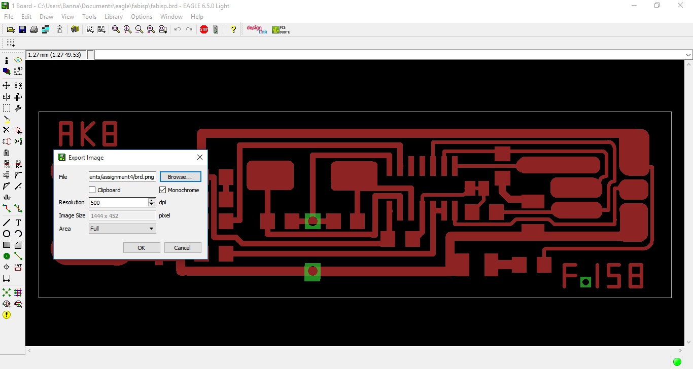
Exporting
Before making the board u must have a png image exported but first u have to show some layers not all of them .
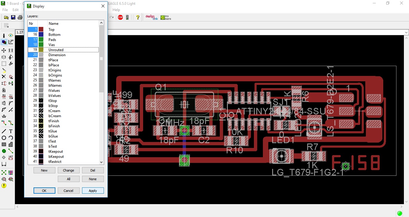
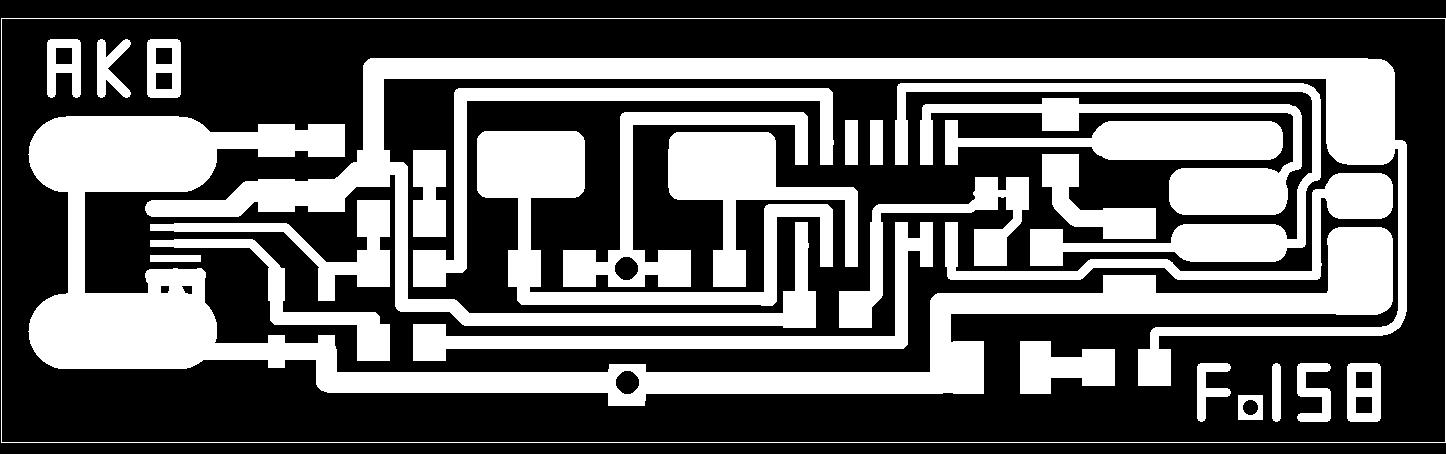
Then export it as an image with resolution 500 dpi and monochrome.
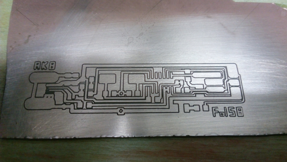
Then here is the exported PNG for the board and PNG for cutting the board.

Installing fab modules
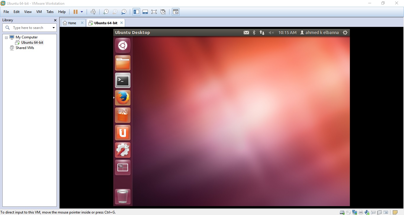
I wanted to use the modela by controlling it with my own laptop and mine has windows 10 , after reading and searching i found that the best way to operate the modela is by linux, so i installed Ubuntu 12.04.5 Desktop (64-bit) on VMware after using a tutorial on how to install ubuntu in vmware.
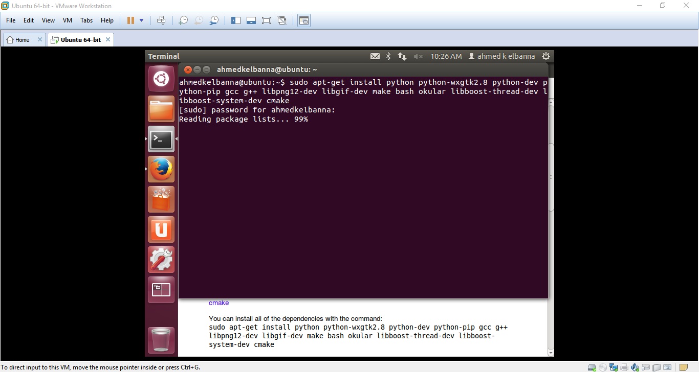
Then i used this guide to install fab modules on linux.
First u have to open a Terminal and past this command by using right click and paste ( sudo apt-get install python python-wxgtk2.8 python-dev python-pip gcc g++ libpng12-dev libgif-dev make bash okular libboost-thread-dev libboost-system-dev cmake ) .
It will ask for the user password enter it and it will start to download the package.
After it downloads and installs, don't close the terminal.
Now you are ready to compile, after downloading the fab modules source, unzip fab_src.zip in a known folder (downloads/fab_src).
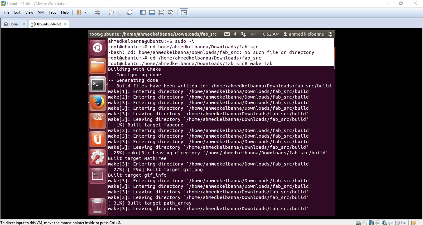
Then type sudo -i (mybe it asks for the user password , enter it).
cd to the folder (cd /home/ahmedkelbanna/downloads/fab_src).
Type make fab, which should compile all executables and copy scripts into bin.
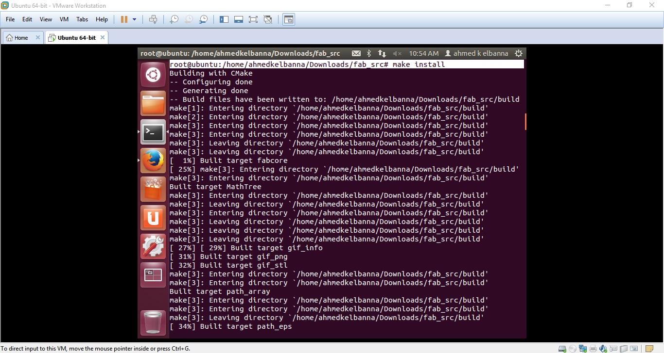
At this point, type make install , it will copy all executables and scripts to /usr/local/bin.
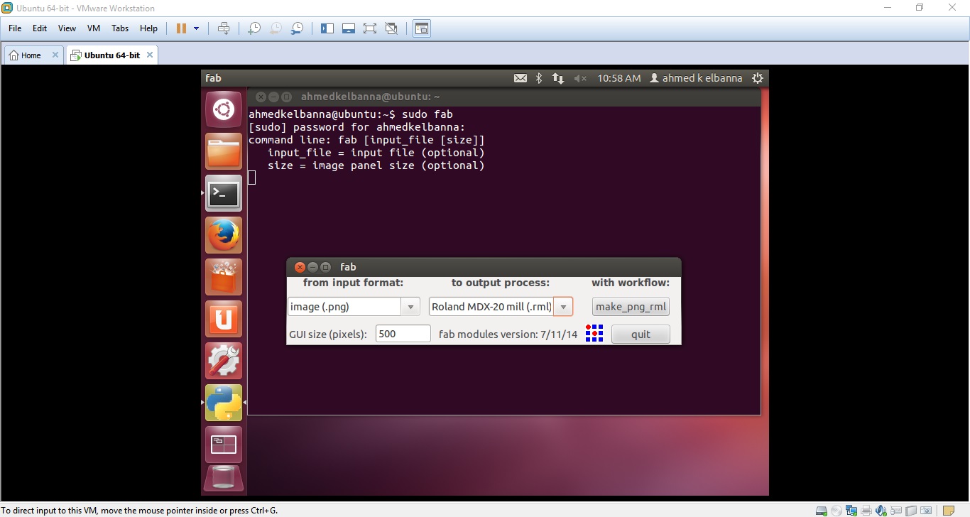
Now fab modules is installed successfuly , close the terminal and open a new one, type sudo fab (it will ask for the user password enter it) , fab application will open then , choose PNG as input format and roland MDX-20 mill (or your machine) as an output process , also enter GUI size pixels 400 .
Then proceed to make_png_rml.
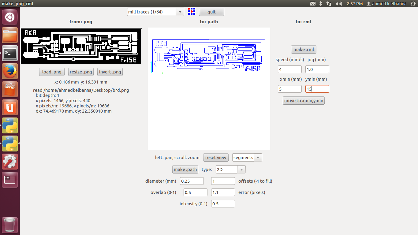
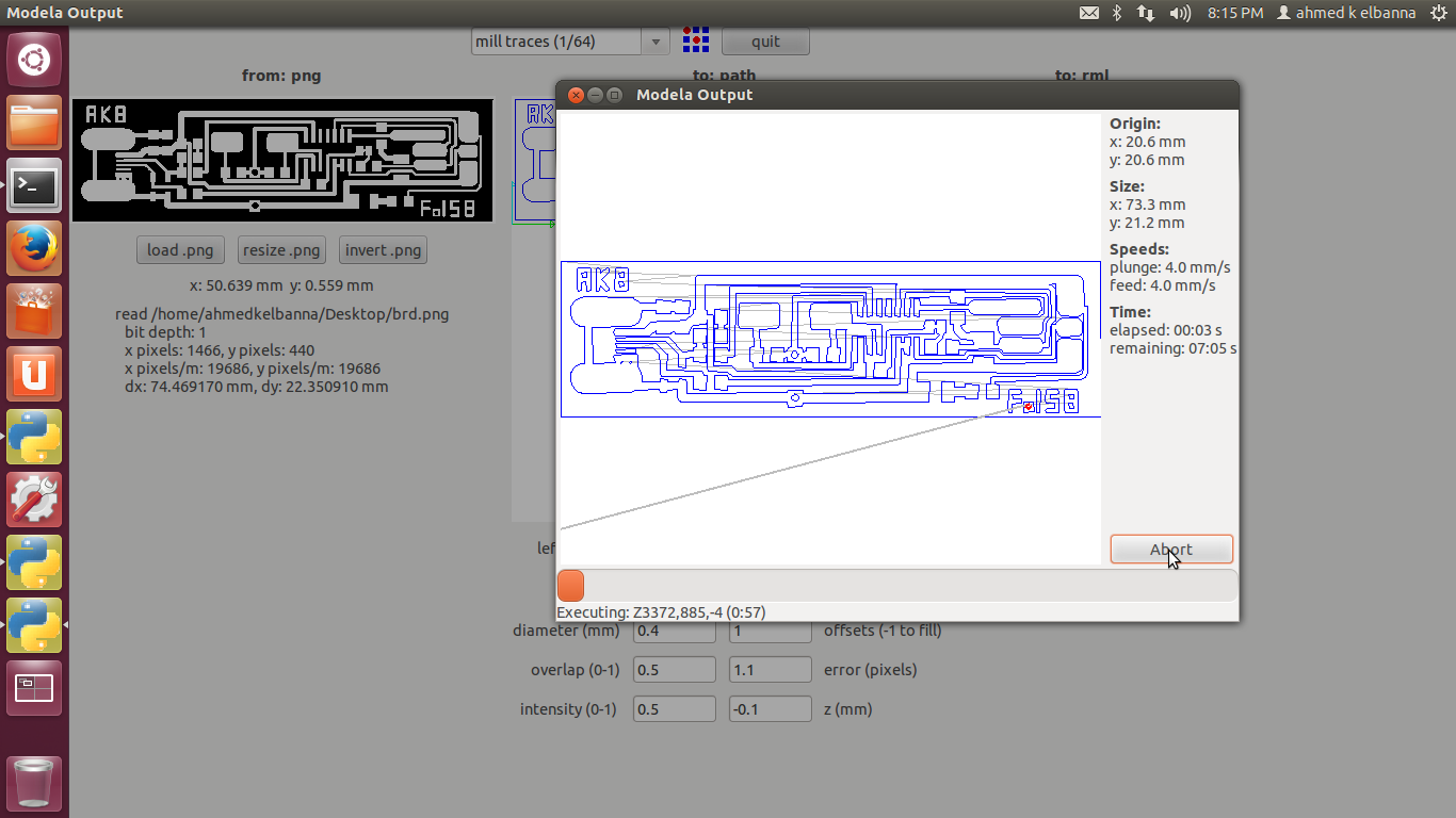
Now load your png board file and choose mill traces 1/64 then press make path after choosing the offsets (how many times to mill around the traces)
I choosed one time only offset, and view as segments and the type of the path 2D.
Then i pressed make .rml , it will take about 10 minutes.
Before sending move the spindle to the origin point ( in my case was 5 in X , 10 in Y) then press move to xmin,ymin
Press send it.
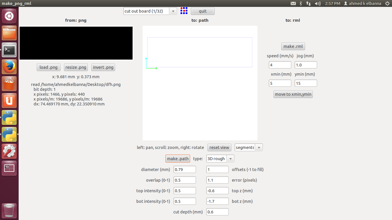
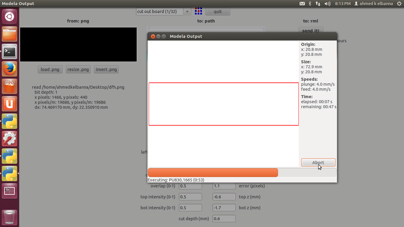
The same steps will be made when cutting but with another configurations.
After loading the png cut file , choose cut out board 1/32 then make .path then make .rml .
It will take about 2.5 minutes.
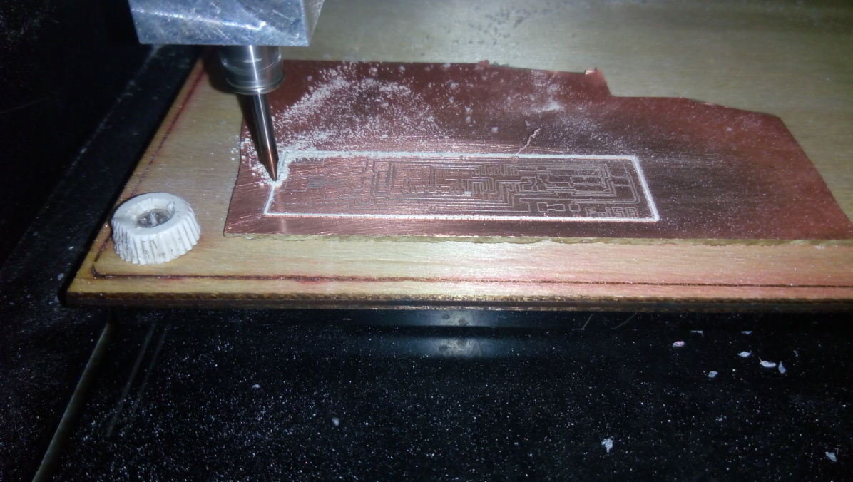
Making the Board
I used 1/64 cutting tool.
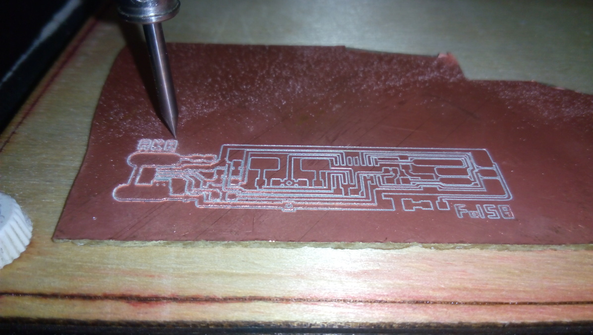
And here is a video while milling .
Here is after milling and cleaning with sand papers.
Check for shorts (i.e. things that shouldn't be connected but are) using the multimeter before moving the pcb or soldering the components onto the board.
Also here is while cutting the board with a 1/32 cutting tool.
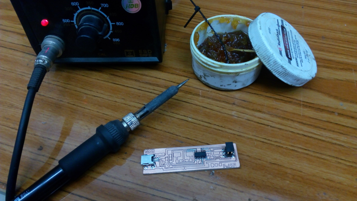
Now soldering time:
I got my soldering station , flux and tin , then i started soldering the mini usb , the Attiny44 and the 2x3 ISP header on the board.
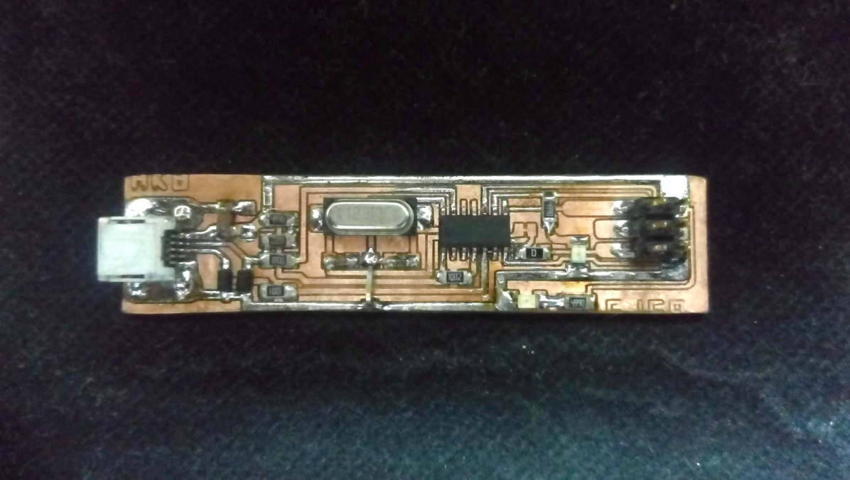
Here is the board after soldering all the components .
Programming the ATtiny44
Before using the FabISP, you need to program the ATtiny44 on it. To do this, you'll need another (programmer)USBasp or arduino as isp or a preprogrammed FABisp or some other in-system programmer (like an AVRISP mkII) .
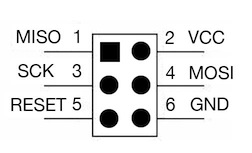
Make sure SJ1 (the solder jumper near the microcontroller) is closed. Connect the 6 pin cable of the USBasp programmer to your FabISP, being sure to orient it correctly (pin 1 to pin 1).
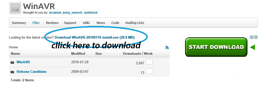
You'll need to install the development tools for AVR microcontrollers. WinAVR is the best for windows , here download it then install .
Then download the firmware file and unzip it in a know place.
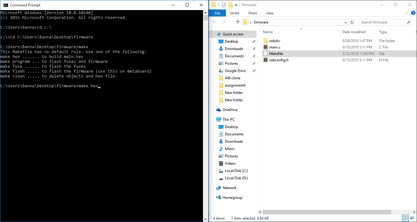
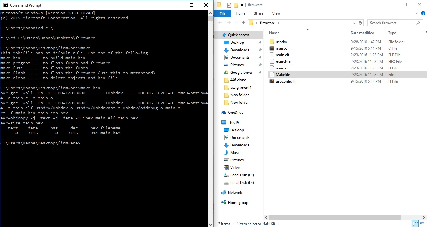
Now open CMD as administrator, then type cd c:\ , then type the location of the firmware folder (cd C:\Users\Banna\Desktop\firmware) , then type make , a list of make commands will appear, type make hex
After pressing enter it will make the hex file that we want to upload it in the 12 mHz fabisp.
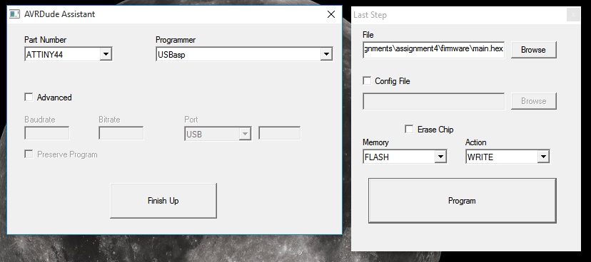
In my case i used AVRDude Assistant program (USPasp software) and choosed the hex file that i made in the last step and make that configurations.
First make sure to erase the chip, the press program.
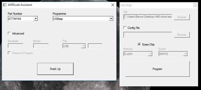
Then uncheck erase chip then press program again.
Here is after writing the code successfully.
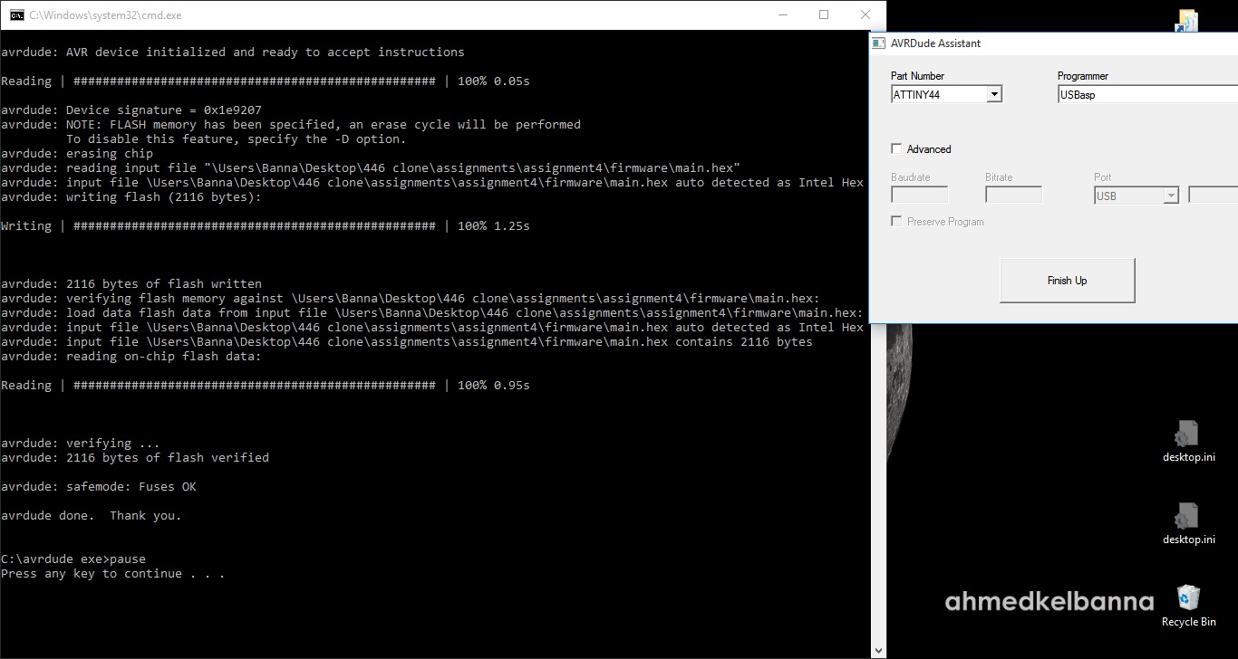
.gif)
Once the ATtiny44 is programmed don't open the SJ1 solder jumper yet (don't disconnect the two pads).
Using the FabISP
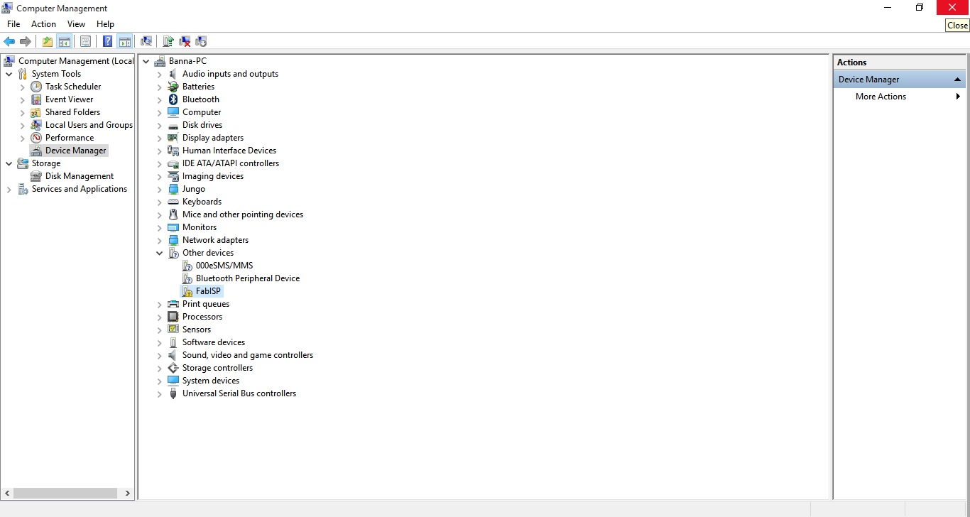
If you connect the FabISP to your computer, it should appear as FABisp that can be seen in other devices in the Device Manager on Windows.
Now you can open the SJ1 solder jumper yet (disconnect the two pads)
The FabISP should work from avrdude without a driver. On Windows, you'll need the Windows USBtinyISP driver built with libusb v1.12 (usbtinyisp w32 driver v1.12.zip). On the 64-bit version of Windows, try these drivers instead. When you plug in the FabISP, point the Windows add hardware wizard at that folder. To use the FabISP from avrdude, supply usbtiny as the -c parameter.
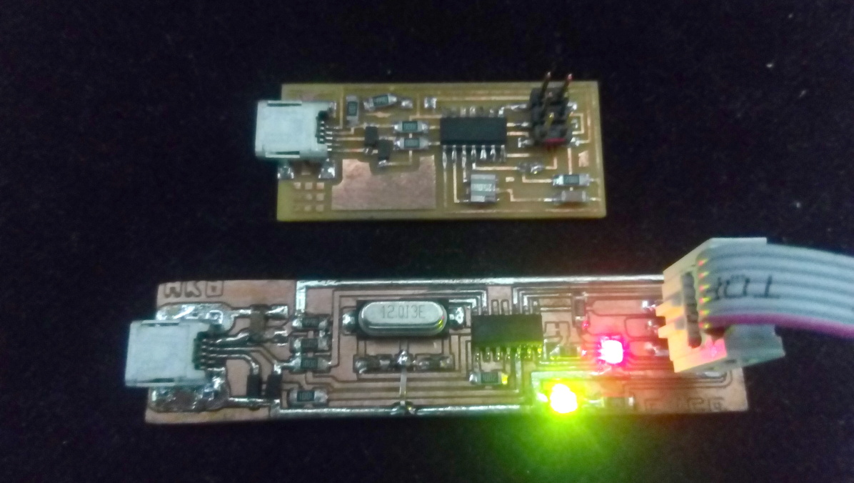
Comparing the ordinary FABisp and my new FABisp
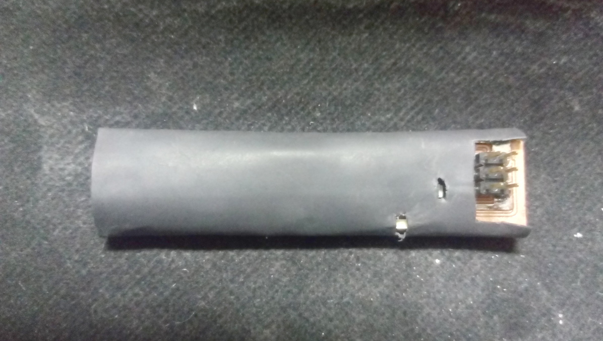
I did warm up the heat shrink yet for testing the board and make sure it works properly .
And here it is ;).