


GENERAL OBJETIVE:

Electronics Production
make an in-circuit programmer
David Andy Valentin Zaerc
programming
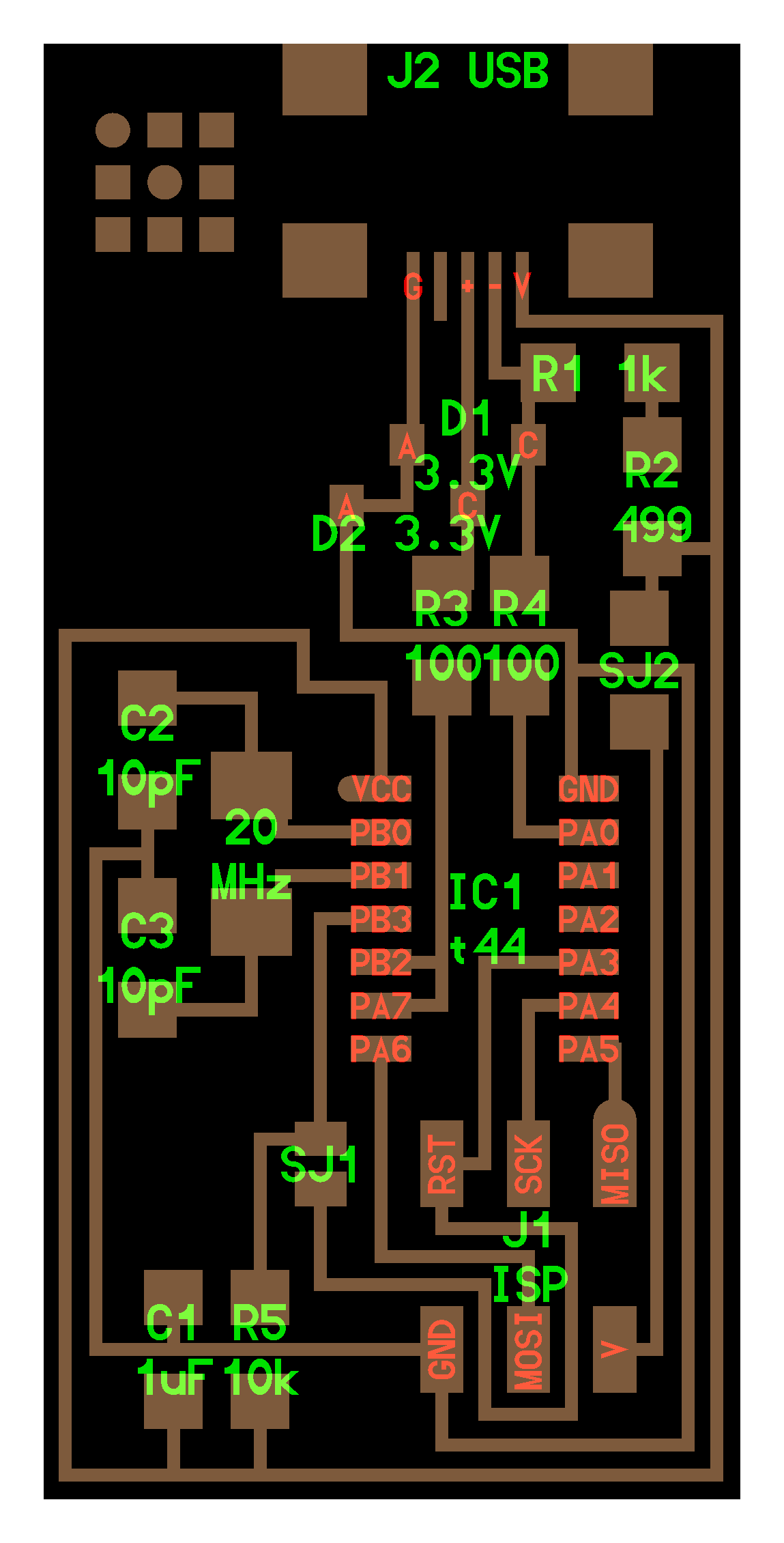
hello.ISP.44.cad board components traces interior
hello.ISP.44.res.cad board traces interior
inventory microcontroller crystal USB connector ribbon connector Zener diode jumper
firmware.zip
USB power
make clean
make hex
(sudo) make fuse (check programmer in Makefile, may need to repeat)
(sudo) make program
desolder SJ1 and SJ2
make IDC ISP cable, connecting header pin 1 to pin 1, check wires
David, Andy, Valentin and Zaerc: the programming for this assignment tablet with the help of tutorials and exercises should be done by.
Having read and reviewed the various exercises of how to tablet, it has decided to carry out as follows:
1. Download the images in PNG format helloISP card (hello.IPS.44.interior and hello.ISP.44.traces)
Download images from here: (tracks) and (Interior).
2. It was Dr. Engrave program, which is part of the software included with the Roland MDX Modela 20 (see tutorial); however, the result was not satisfactory start, this is because the software that does not compensate the diameter of the cutter, so self must perform this process on the image when working on the software.

Figure 1 Interface Dr. Engrave
3. To facilitate the realization of the tablet and not having to manually compensate the diameter cutter was used Fab Modules; however, it was not possible to use the online version and therefore settled in UBUNTU 15.10 with the help of tutorial page and the tablet was made, here I perfectly on the first try and have not had to compensate , using only the cutter indicated.

Figure 2 Interface Modules Fab
4. After sending the Roland manufacture MDX20, a bit must be sanded to remove the tablet remaining waste removing rust and in case there.
You must use an average sandpaper to remove material waste, and after removing the waste is to use a very fine sandpaper or an eraser to remove the rust and facilitate the welding process.

Figure 3 Tablet PCB without sanding

Figure 4 Tablet PCB Sanded
5. When you have the clean tablet can be performed more easily the welding process components, in this case should be used as a guide.
Download image hello.ISP.board
In the image indicates the position downloaded and accommodation that should bring the components to be welded on the tablet, recommendations for the welding process the following are made:
a) While you are sanding and cleaning tablet, preheat the soldering iron. If you have a workstation preheated to 50% of its maximum power and if you do not have a connect about 5 minutes before starting the welding process.
b) Do not use more than 40 watts of power soldering iron, to avoid excessively raising the temperature of the micro-controller and damage it.
c) If treated surface mount components, tinning tracks largely facilitate the welding process. Tinning term refers to putting on the ski welding copper by heating and depositing very little welding.
d) To connect the SJ1 elements and SJ2 can be done with a wire, component continuity or with a pair of header's male and a jumper, this in order to make it look more aesthetic and facilitate the connection process .

Figure 5 Drilling Tablet hello.ISP
To facilitate assembly and welding process can be performed where perforations entering the ends of the pieces, both SJ1 and SJ2 for connectors and connector apara ISP.

Figure 3 Tablet PCB without sanding

Figure 7 tablet hello.ISP and programmer mkii AVRISP
6. Upon completion of the welding process using a programmer, in this case a AVRISP mkii (Figure 7), should make use of AVRStudio software for loading the program to be executed by the micro-controller to operate as desired in this case programmed to function as a programmer. The steps for programming the tablet is
a) Download the hello.isp.hex file (compiled the scheduled hello.ISP.c).
b) AVRStudio Open the Tools menu and find the application of "Device Programmer"
c) Load the program to the tablet (see tutorial).

Figure 8 Programming Interface AVRStudio