Week 6 - Electronics Design
Assignment
redraw the echo hello-world board
- add (at least) a button and LED (with current-limiting resistor)
- check the design rules, and make it
- extra credit: simulate its operation
Index
Schematics
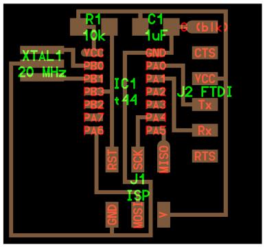
The assignment is to redraw the following board and add a button and LED to it:
First step - go through some Eagle tutorials:
- Youtube videos by Jeremy Burns: part 1, part 2.
- MIT Electronics Design 101: also get the PPT.
- Fab Academy tutorial.
- SparkFun schematic and board tutorials.
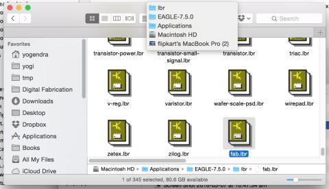
Install Eagle, then download fab.lbr (library of components) and place it into the lbr folder in your Eagle installation.
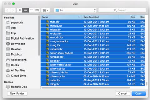
Switch to Eagle and click the menu-item for “Library -> Use”, and select all the files and click open.
Similarly, download fab.dru (design rules) and place it in the dru folder in the Eagle installation.
Create a new project in Eagle and add a schematic to it.
Add components from the library (look for components directly under the Fab folder in the Add Dialog):
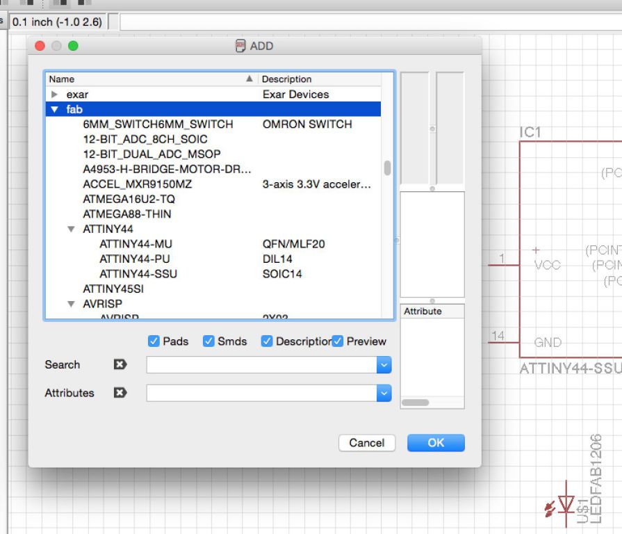
- ATtiny44-SSU: datasheet
- 20mhz resonator: ATtiny has an inbuilt 8mhz clock, but this one is faster and more accurate
- 6mm Switch Omrom
- AVR ISP SMD header: for programming the board
- FTDI SMD header: powers the board and allows it to speak to the computer
- 10K resistor x 2
- 1µF capacitor
- GND: Ground
- VCC: Power supply
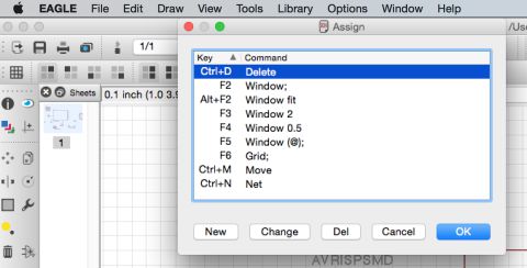
Pro tip: Assign keyboard shortcuts to switch quickly between commands by clicking the menu item “Options => Assign”.
To figure out the resistor required for the LED, check the LED datasheet. It mentions a Voltage - Forward (Vf) of 2.1V and DC Forward Current of 30mA (Ifc). To calculate the required resistance:
 R = (Vs - Vf) / Ifc
=> R = (5V - 2.1V) / 0.03A
=> R = 96.67 Ohms
Given a requirement of 96.67 Ohms, I will use a 100 Ohms resistor. The power dissipation in the resistor would be:
 P = VI
=> P = 2.9V x 0.03A
=> 87mW
To check if the 100 Ohm resistor would support this, find its part number from the FabLab Inventory and look it up at the vendor’s site.
In this case, the 100 Ohm resistor has a power rating of 0.25W, which is well above 0.087W that it is expected to dissipate.
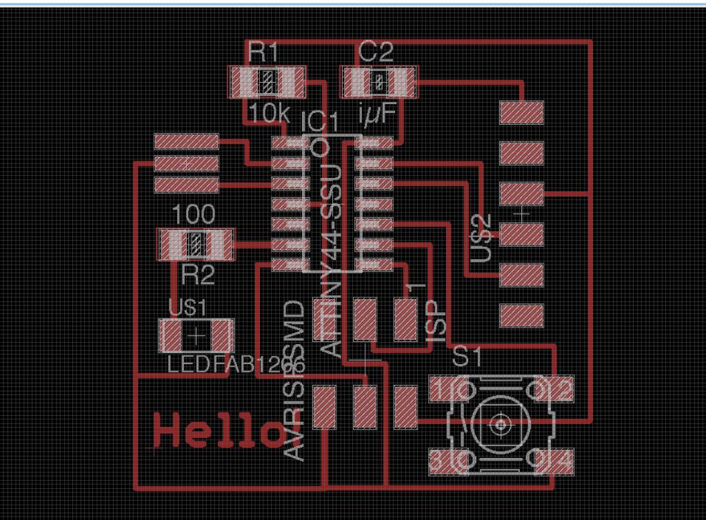
Here is the final schematic.
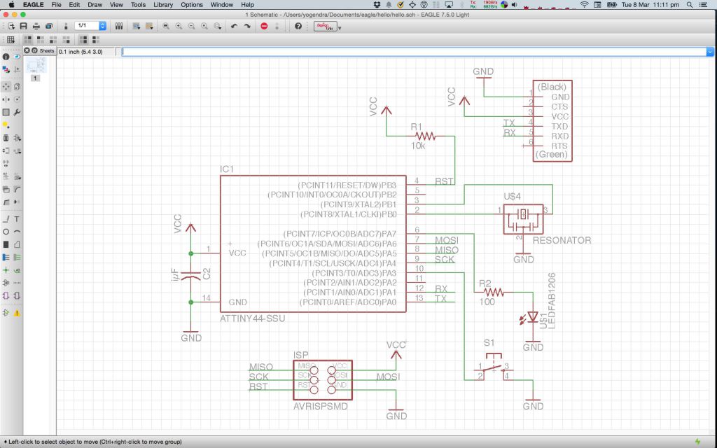
It took a surprisingly long time to create this, especially figuring out how to connect the components. Creating keyboard shortcuts for the commands helped a lot.
Layout
With the schematic done, switch to board view.
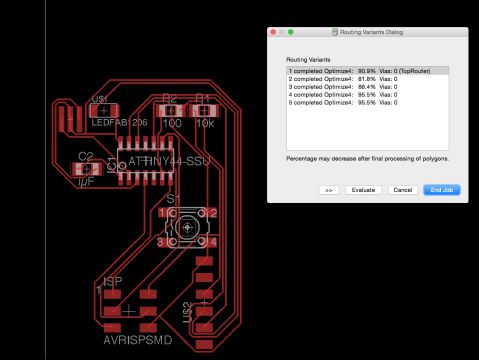
First I attempted Autorouting. Here is the output with Top = Auto and Bottom = NA, since I wanted a single side board only.
After this I manually routed the traces using the tutorial as a guide.
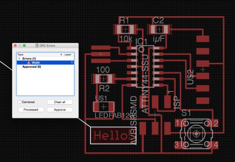
Then I ran the fab Design Rule Checks, which revealed a few traces were too close to each other and the font width was too small.
I changed the trace width from 0.016 in to 0.012 in and increased the font width, and that fixed the errors.
Here is the final layout:
Milling
Export the layout as a monochrome png at 500 dpi. Here is the output:
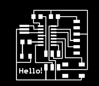
Then edit it in Gimp to crop and set a white border - change Canvas size, add 20 px to height and width, center it then Image -> Flatten, this will add a 20px white border.
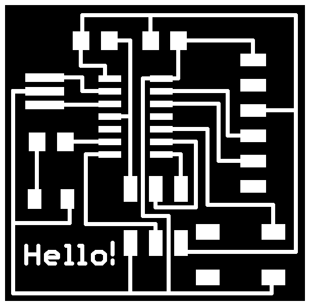
Then create the outline image for milling by bucket filling all the internal areas with white in Gimp, and adding a 20 px black border.

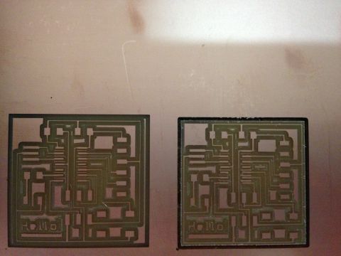
The traces for the board turned out to be too narrow and were peeling off in some places, as shown in the image below.
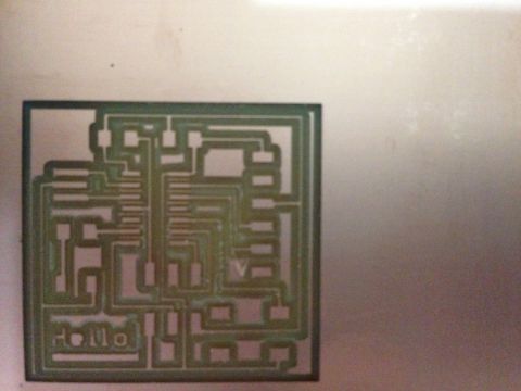
I increased the trace widths from 0.012 in to 0.015 in and milled again. This was the result:
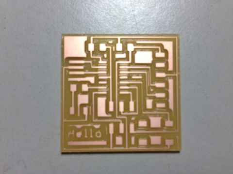
In the 2nd board some of the traces were quite narrow, but I went ahead and cut it out, here is the final milled board:
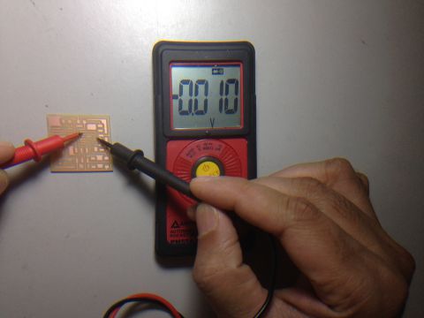
I tested the traces for current flow using a multimeter and it confirmed that these were working fine:
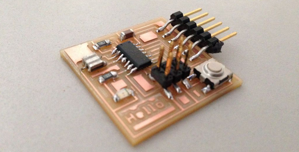
Last step was to stuff the board. Here is the completed board:
Original Files
- Schematic: hello.sch
- Board layout: hello.brd
- Milling traces image: hello-traces.png
- Milling outline image: hello-outline.png
Notes
ATtiny44-SSU microcontroller
- Datasheet
- 8-bit microcontroller
- Modified Harvard architecture
- Harvard architecture uses separate address space for data and instructions unlike Von Neumann architectures. This allows concurrent and faster access to instructions and data even without caches.
- Modified Harvard architecture has separate instruction and data caches backed by a shared memory.
- In-system programmable, EEPROM (Electrically Eraseable Programmable ROM)
- RAM
- Special Function Registors (part of RAM)