Week 20 - Final Project Development
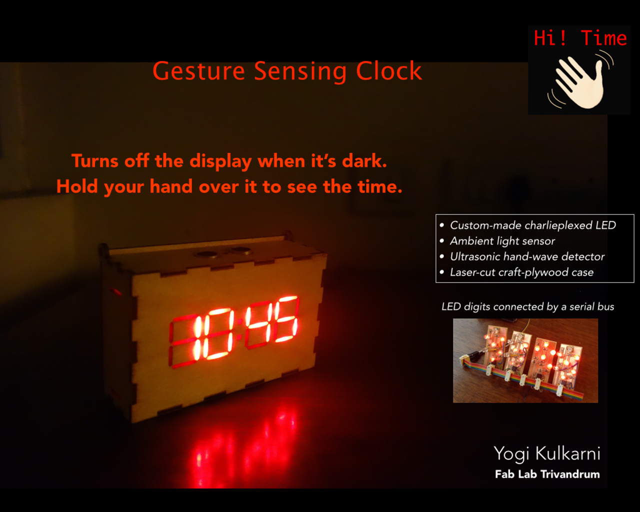
Here’s the final product:
And here’s the story of how it was built:
Thu, May 12th
Given the plan for the final project, which is documented on the Applications & Implications page, I’m starting prototyping some of the key pieces that are required for the clock.
The first is the Motion Detector. I need a way to detect a hand-wave about 1 foot above or in front of the clock.
However I like working outside-in, i.e. starting with the end product and working backwards to the details. Therefore, I’m starting off creating the design in Rhino.
Digit Test Cuts
First step was to design the digits and try out a test cut to get the tolerances correct for the acrylic segments to fit into the craft plywood outlines.
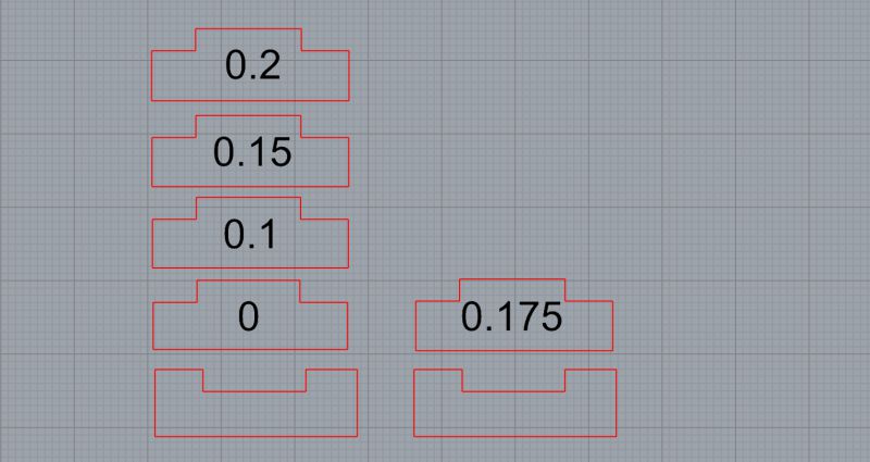
Here is the design in Rhino.
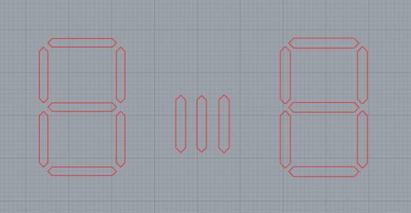
The original digit design is on the left, this is used for the plywood cut.
The one on the right is used for the acrylic cut, it is increased in size by 1.15 mm (using Offset command).
The ones in the middle are the different sizes (0.1mm, 0.15mm, 0.2mm offset) to get the acrylic fit just right.
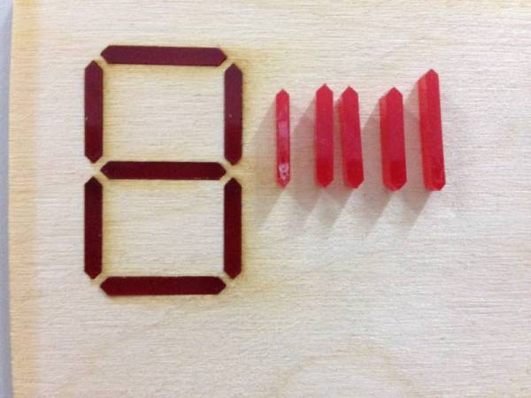
0.15mm increase had the best fit, here are the cut pieces:
“2” being displayed with the test digit on the 7-segment board:
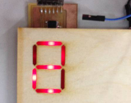
Looks like I might have to add 2 LEDs instead of 1 for each segment.
Fri, May 13th
Today I went to the local electronics market to buy a bunch of things I needed for the project. It turned out to be very productive as I was able to get pretty much everything I needed:
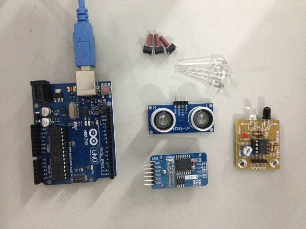
- RTC DS3231 module
- HCSR04 Ultrasonic sensor module
- IR Transceiver
- Bright LEDs
- Arduino Uno for prototyping
- Jumper cables
- Push buttons with longer shaft
For motion detection I plan to try the ultrasonic sensor first since I want detection over at least 1+ ft, which the IR sensor isn’t capable of.
Ultrasonic sensor test
As per the datasheet and user-guide the sensor requires a 10µs pulse on it’s Trigger pin, which causes it to send out 8 40khz sound pulses and waits for the echo back. The distance to the object can be calculated by multiplying the time taken by the speed of sound.
I used an Arduino sketch from here.
#include <NewPing.h>

#define TRIGGER_PIN  12
#define ECHO_PIN     11
#define MAX_DISTANCE 50

NewPing sonar(TRIGGER_PIN, ECHO_PIN, MAX_DISTANCE);

void setup() {
  Serial.begin(9600);
}

void loop() {
  delay(500);
  int uS = sonar.ping();
  Serial.print("Ping: ");
  Serial.print(uS / US_ROUNDTRIP_CM);
  Serial.println("cm");
}
Here is a video showing the test:
Real Time Clock Test
Next step is to test the RTC module. Here is the DS3231 datasheet.
I used this guide and sketch to test the module.
I hooked up the I2C SDA (data) and SCL (clock) to pins A4 and A5 respectively.
Here’s the sketch from the article:
#include "Wire.h"
#define DS3231_I2C_ADDRESS 0x68
// Convert normal decimal numbers to binary coded decimal
byte decToBcd(byte val)
{
  return( (val/10*16) + (val%10) );
}
// Convert binary coded decimal to normal decimal numbers
byte bcdToDec(byte val)
{
  return( (val/16*10) + (val%16) );
}

void setDS3231time(byte second, byte minute, byte hour, byte dayOfWeek, byte
dayOfMonth, byte month, byte year)
{
  // sets time and date data to DS3231
  Wire.beginTransmission(DS3231_I2C_ADDRESS);
  Wire.write(0); // set next input to start at the seconds register
  Wire.write(decToBcd(second)); // set seconds
  Wire.write(decToBcd(minute)); // set minutes
  Wire.write(decToBcd(hour)); // set hours
  Wire.write(decToBcd(dayOfWeek)); // set day of week (1=Sunday, 7=Saturday)
  Wire.write(decToBcd(dayOfMonth)); // set date (1 to 31)
  Wire.write(decToBcd(month)); // set month
  Wire.write(decToBcd(year)); // set year (0 to 99)
  Wire.endTransmission();
}

void setup()
{
  Wire.begin();
  Serial.begin(9600);
  // set the initial time here:
  // DS3231 seconds, minutes, hours, day, date, month, year
  setDS3231time(0,14,20,6,13,5,16);
}

void readDS3231time(byte *second,
byte *minute,
byte *hour,
byte *dayOfWeek,
byte *dayOfMonth,
byte *month,
byte *year)
{
  Wire.beginTransmission(DS3231_I2C_ADDRESS);
  Wire.write(0); // set DS3231 register pointer to 00h
  Wire.endTransmission();
  Wire.requestFrom(DS3231_I2C_ADDRESS, 7);
  // request seven bytes of data from DS3231 starting from register 00h
  *second = bcdToDec(Wire.read() & 0x7f);
  *minute = bcdToDec(Wire.read());
  *hour = bcdToDec(Wire.read() & 0x3f);
  *dayOfWeek = bcdToDec(Wire.read());
  *dayOfMonth = bcdToDec(Wire.read());
  *month = bcdToDec(Wire.read());
  *year = bcdToDec(Wire.read());
}

void displayTime()
{
  byte second, minute, hour, dayOfWeek, dayOfMonth, month, year;
  // retrieve data from DS3231
  readDS3231time(&second, &minute, &hour, &dayOfWeek, &dayOfMonth, &month,
  &year);
  // send it to the serial monitor
  Serial.print(hour, DEC);
  // convert the byte variable to a decimal number when displayed
  Serial.print(":");
  if (minute<10)
  {
    Serial.print("0");
  }
  Serial.print(minute, DEC);
  Serial.print(":");
  if (second<10)
  {
    Serial.print("0");
  }
  Serial.print(second, DEC);
  Serial.print(" ");
  Serial.print(dayOfMonth, DEC);
  Serial.print("/");
  Serial.print(month, DEC);
  Serial.print("/");
  Serial.print(year, DEC);
  Serial.print(" Day of week: ");
  switch(dayOfWeek){
  case 1:
    Serial.println("Sunday");
    break;
  case 2:
    Serial.println("Monday");
    break;
  case 3:
    Serial.println("Tuesday");
    break;
  case 4:
    Serial.println("Wednesday");
    break;
  case 5:
    Serial.println("Thursday");
    break;
  case 6:
    Serial.println("Friday");
    break;
  case 7:
    Serial.println("Saturday");
    break;
  }
}
void loop()
{
  displayTime(); // display the real-time clock data on the Serial Monitor,
  delay(1000); // every second
}
Most of the code is for formatting the time for display. The actual interaction is quite simple, and converts data between Binary Coded Decimal and Decimal. The RTC uses BCD for each part of the time (H:M:S, etc.).
Here is a video showing the test the time is printed out every second.
Sat, May 14th
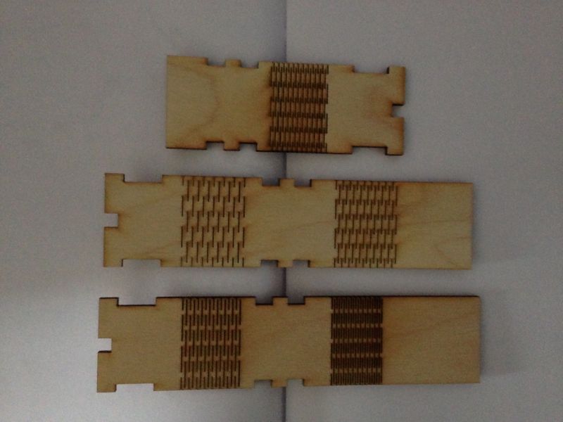
Today I designed the cover for the clock in Rhino and did test cuts to get the press-fit tolerances and flexures correct.
Here is the design for the testing press-fit tolerance. I kept one side constant and increased the size (using Offset command) of the other pieces by 0.1 - 0.2 mm (The laser cutter has a kerf of 0.2 mm).
These are the test cuts. 0.175 had a good fit, I’ll be going with 0.18.
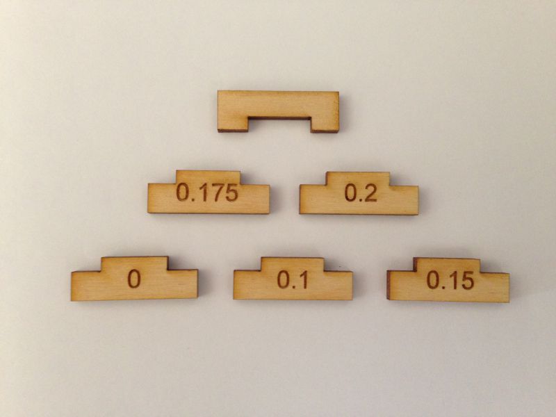
I have to remember to add chamfers to make it easier to slide the pieces in.
The flexures took longer than expected and I had to try a number of variations. Here is the design:
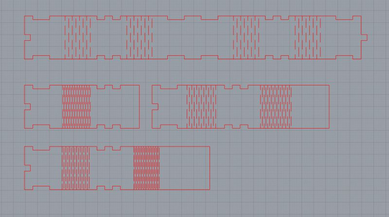
The one which worked best had 1 mm horizontal spacing and 2 mm gap between each vertical cut, which is the bottom right onw below:
Sun, May 15th
Today my goal is to fabricate a digit board with the new bright LEDs I’ve bought.
I checked the voltage and current range for the LED using a DC power supply.
At a steady current of 10mA, the LED is off at 1.4V and brightest at 2.2V.
I was considering having 2 LEDs for each segment, but that significantly increases the effort to solder so many LEDs and resistors (if 2 LEDs for each segment are arranged in parallel with their own resistor).
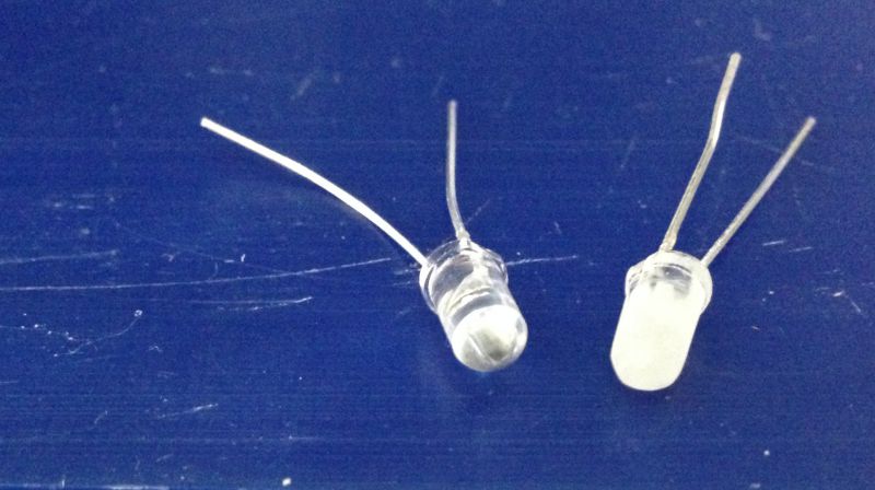
What I really want is a more diffused light coming from the LED. I found a neat hack on Instructables to do this by sandpapering the LED.
Here is the sandpapered one next to a normal one:
Here is the output of the 2 when connected to a power source with 2.1V and 10mA:
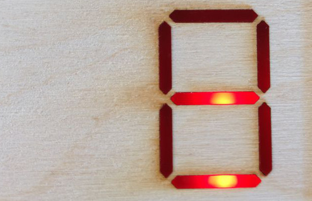
The middle horizontal segment is the diffused one. The difference is not pronouned in the photo but the sandpapered one is definitely diffusing the light.
This is an excellent hack… it saves me a lot of time and effort!
Next step is to fabricate the digit board with the new LEDs.
I plan to drill vias for the LED leads and solder them to the underside of the board. I don’t
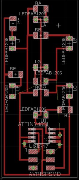
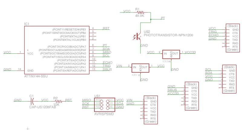
I used the 7-segment board from the Output Devices week. However, I noticed that I had arranged the resistors and LEDs in the wrong order. The resistors should come before the LED, because otherwise the LED gets the full voltage rather than the divided voltage.
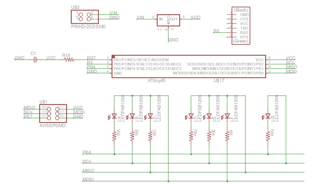
I changed the schematic to reflect this:
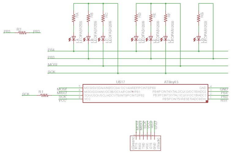
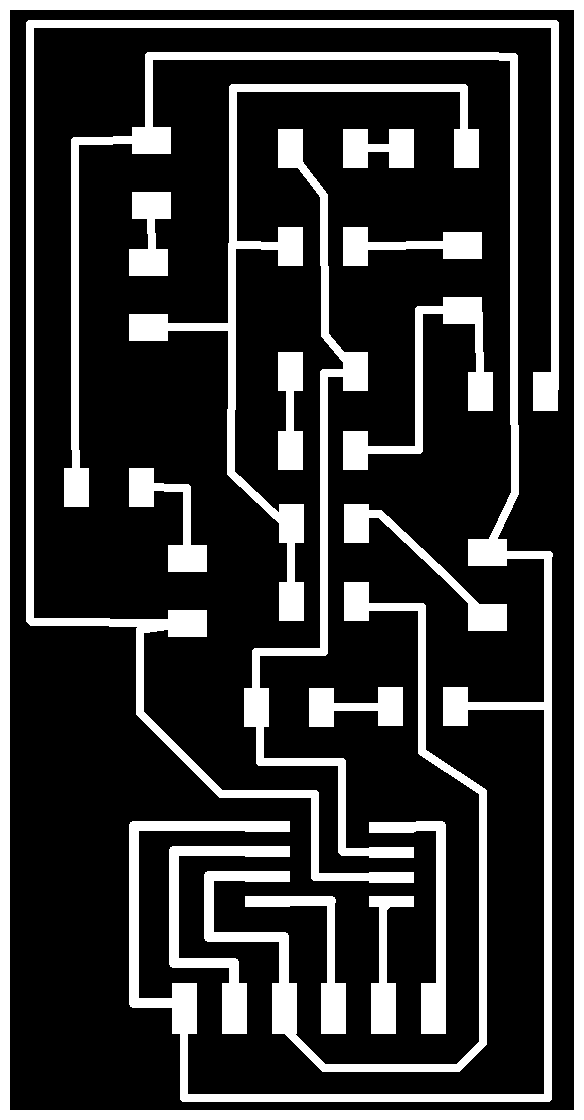
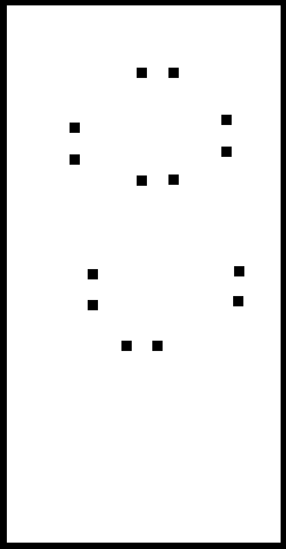
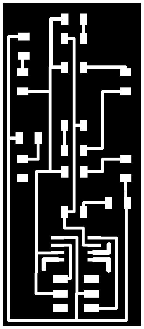
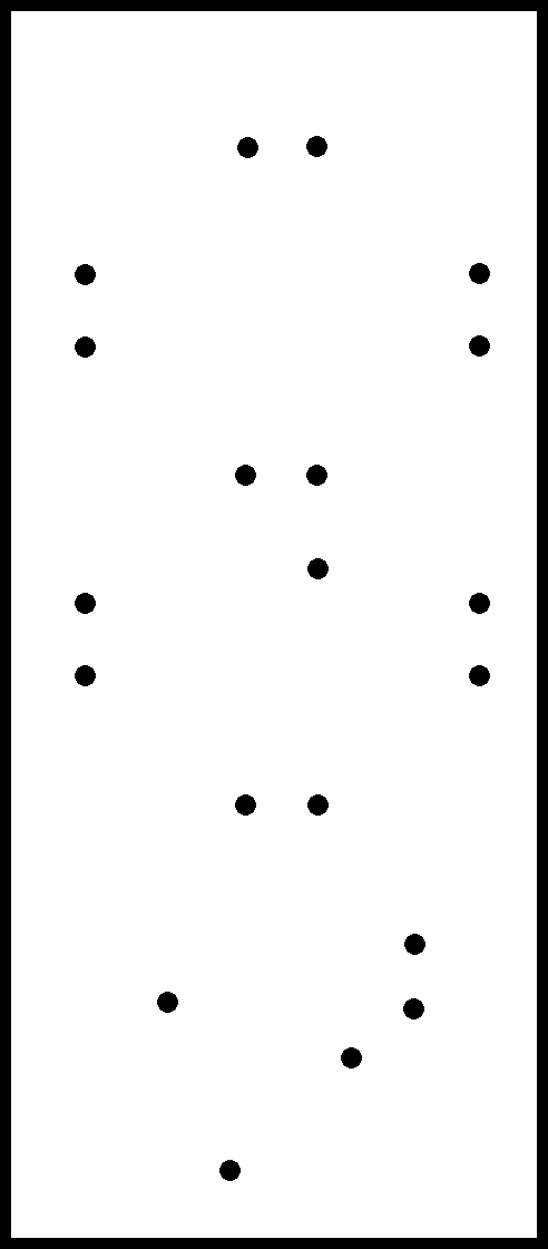
And created a new board layout. Routing traces took a few hours. I added vias for the LEDs and created the traces and outlines:
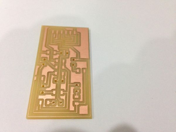
Here is the milled board:
And here it is stuffed:
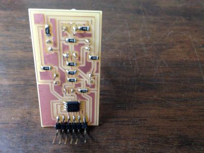
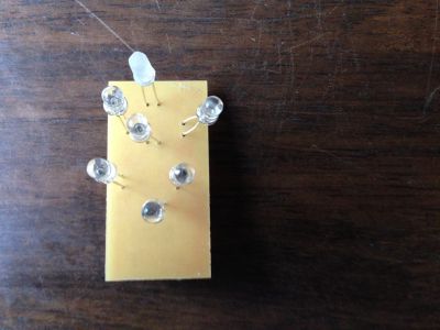
The through hole LED contacts aren’t very strong and 1 of them snapped off.
Mon, 16th May
I headed back to Bangalore last night. Have to watch over my kids for the next 10 days since my wife is travelling.
I programmed the board with the 7segment and only 3 of them lit up… need to debug this.
I’m not liking the through-hole LED setup because it is not strong and can come loose quite easily. My idea with packing the board LEDs close together was that I could bend their leads into place to form a wider 7-segment digit. I don’t think thats going to work out too well.
I might use the surface mount LEDs as before.
The next step is to prototype the code for all the boards hooked up to a central Arduino and talking I2C amongst themselves. I will fabricate the remaining boards once I’m back in Trivandrum.
Tue, 31th May
I’m back in Trivandrum. I have 4 days to complete my project and head back to Bangalore. Lots to do!
-
Need to create a new board with bright LEDs mounted on the surface
- Have to figure out the IDC header position on the 7-segment board so that it doesn’t interfere with the LED position, which needs to be close to the clock surface
- Will mount the IDC header on the under-side as a through-hole component. Need to ensure the pads on the surface are large enough to create good contact with the pins.
- I’m using an incorrect resistor of 499 ohms. Given 5V source voltage, 2V LED forward voltage if I use a 100 ohm resistor the current through the LED would be 29mA, which is under the max of 30mA. Ideally it should be around 20mA but we only have a 100 ohm and 499 ohm resistor in the lab.
- Have to figure out the IDC header position on the 7-segment board so that it doesn’t interfere with the LED position, which needs to be close to the clock surface
-
Need to figure out the power source and the voltage & current through each of the boards
- 4 x 7-segment board
- Each board with 7 LEDs, but these are multiplexed, so only 1 LED is on at a time for 1 ms.
- Each LED requires 2.1 V and 20 mA
- 4 x 20 mA == 80 mA
- Ambient light sensor
- 5V, 10mA
- DS3231 RTC module
- Active: 3.3 V - 5 V, 200 µA - 300 µA
- HC SR04 - Ultrasonic module
- 5V, 15 mA
Given these requirements, the 7-segment LEDs would consume the most current. A 9V battery providing 1000mAh would last for less than 12.5 hours (given 80 mA for 4 LEDs, see above)
Therefore, an external power source would be needed. I will go with a 5V 2A DC adapter with a barrel jack or micro USB connector, since these are easily available.
- 4 x 7-segment board
-
Design the controller board
-
Design and laser-cut the case
7-Segment Board Redesign
For the LED board, I realized that I2C won’t work because I have only 1 spare pin on the ATtiny45. While I could reuse the RESET pin, it involves setting the RSTDISBL fuse and using a jumper when programming it. This seems needlessly complex. Instead I’ll use a single-wire serial protocol - RS-232 to communicate with all the boards. These anyways only read data from the master so a single wire should be sufficient.
I also aligned the LEDs on the board to the correct location using a set of wire guidelines.
I replaced the FTDI headers with an ISP header so that I can have a continuous strip of jumper cables with ISP connectors hanging off them which can connect the 4 7-Segment digits.
I then routed the board, created many vias and have the PNGs ready for milling. This time I’ve added wider pads for the vias to provide a stronger contact with the LED leads.
Wed, 1st Jun
The traces are being milled right now.
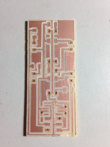
Here is the board right after milling. Notice the bottom right corner has a trace that got cut when I was trying to pry out the board.
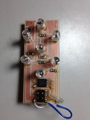
Stuffing the board took a few hours getting all the vias done.
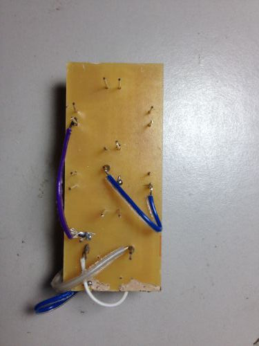
The wires look quite untidy and I’m concerned about shorts, will add some glue to hold the wires in place and provide some insulation.
It did get programmed on the first shot. Here it is displaying each digit:
It seems to work correctly only with 3.3V power. With 5V, multiple LEDs light up for each segment. I thought I’d got the voltage calculations correct this time.
Next step is to program it to accept inputs over single-wire serial interface.
Serial Communication for 7-Segment Board
To test this I connected an Arduino Uno (which would act as the master) and the 7-segment board. I connected the TX pin on the Arduino to the MISO (PB1) pin on the 7-segment.
I used Neil’s sample code to check for data on the pin, read a character off it, and the display the digit.
Here is the Arduino code, it mimics a clock sending a digit every sec:
void setup() {
  // initialize both serial ports:
  Serial.begin(9600);
}

static int i = 0;
static int t = 0;
static int sleep = 10;

void loop() {
  Serial.write(i);
  delay(sleep);
  t = t + sleep;
  if (t >= 1000) {
    t = 0;
    i = ++i % 9;
  }
}
I’ve been playing around with the 7segment code to get it to display digits sent over serial. The basic interaction worked fine. Now I’m trying to get it to work using interrupts, because without them there is a visible flicker as the code waits for a start bit signal on the serial line. This happens even if the wait is as small as 1 ms.
Thu, 2nd Jun
Whats left to do before I leave on Sat:
- Get serial comm using interrupts working
- read up - 1, try small experiments: 2 hr
- Laser cut the case: 6 hr
- case design with easily openable back cover
- Rhino design:
- add components and boards with exact dimensions to design
- back cover with magnets
- plywood placement guides for LEDs
- shelves for board placement
- position components: digit boards, hole for phototransistor, ultrasonic sensor, RTC
- test cuts: 1 hr
- Rhino design:
- final cut: 0.5 hr
- case design with easily openable back cover
- Controller board design: 6 hr
- schematics: 2 hr
- layout: 2 hr
- milling & stuffing: 2 hr
- Mill and stuff 3 digits boards: 6 hr
- 6 hrs: 3 x 2 hrs each
-
Produce separator board (or connect it to the controller directly): 3 hr
- Program the controller: 3+ hr
What if I don’t use buttons on the clock face for setting the time? These look clunky and I don’t like the lack of tactile feedback in capacitive buttons.
Instead what if time is set by connecting to a host over USB and sending it a serial command to set the time. The next version could support a bluetooth interface. I like this approach better.
Serial Comms Problems… and a Solution!
NOTE TO SELF: When setting the clock prescaler, remember to update the makefile so that the F_CPU argument takes effect.
Wasted some precious time debugging this today!
Found an excellent article on implementing UART in software on the ATtiny85.
Just discovered a big gotcha, that you have to use PCINT0_vect even if you are setting up an ISR for PCINT1. I checked the avr header file iotnx5.h and confirmed that only PCINT0_vect is defined. There is no PCINT1_vect! Shouldn’t the compiler have complained about this!?
avr-libc page says this:
The ISR() macro cannot really spell-check the argument passed to them. Thus, by misspelling one of the names below in a call to ISR(), a function will be created that, while possibly being usable as an interrupt function, is not actually wired into the interrupt vector table. The compiler will generate a warning if it detects a suspiciously looking name of a ISR() function (i.e. one that after macro replacement does not start with “_vector”).
So, your on your own if you misspell the vector. I tried with ISR(FOO) but got no compiler warning.
The following code works (snippet only, full code is in the original files linked below):
volatile int i = 1;

ISR(PCINT0_vect) {     // Doesn't work if this is PCINT1_vect.
   display(i++, 3000);
   i %= 9;
}

int main(void) {
    //
    // set clock divider to /1
    //
    CLKPR = (1 << CLKPCE);
    CLKPR = (0 << CLKPS3) | (0 << CLKPS2) | (0 << CLKPS1) | (0 << CLKPS0);

    DDRB &= (~ (1 << PB1));         // set serial-in pin to input
    PORTB |= (1 << PB1);            // ... and enable pull-up by driving it high

    GIMSK |= (1 << PCIE);           // enable pin change interrupt
    PCMSK |= (1 << PCINT1);         // ... only for serial-in pin

    sei();                          // enable interrupts globally

    while(1) {
       ;
    }

    return 0;
}
I set up the correct ISR and copied over the get_char logic into it, but it just wouldn’t work. The fix was to check whether the pin was indeed 0 indicating a start bit otherwise return. Here is the interesting code snippet:
ISR(PCINT0_vect) {          // has to be PCINT0_vect and not PCINT1_vect even though I'm enabling PCINT1
    volatile unsigned char *pins = &serial_pins;
    unsigned char pin = SERIAL_IN_PIN;
    char tmp = 0;
    char *rxbyte = &tmp;

    //
    // read character into rxbyte on pins pin
    //    assumes line driver (inverts bits)
    //
    *rxbyte = 0;

    // ---- FOLLOWING 2 LINES WERE THE FIX ----
    //
    // assume we have just seen the start bit (pin going low)
    // check that it is indeed 0, otherwise return
    if pin_test(*pins, pin)
        return;

    //
    // delay to middle of first data bit
    //
    half_bit_delay();
    bit_delay();
    //
    // unrolled loop to read data bits
    //
    if pin_test(*pins,pin)
      *rxbyte |= (1 << 0);
    else
      *rxbyte |= (0 << 0);
    bit_delay();

// ... remaining code omitted
Clock Case Production
Spent the evening designing the clock case in Rhino. I simplified the design and based it off Sibu’s box:
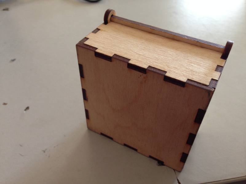
Here is the final design I came up with:
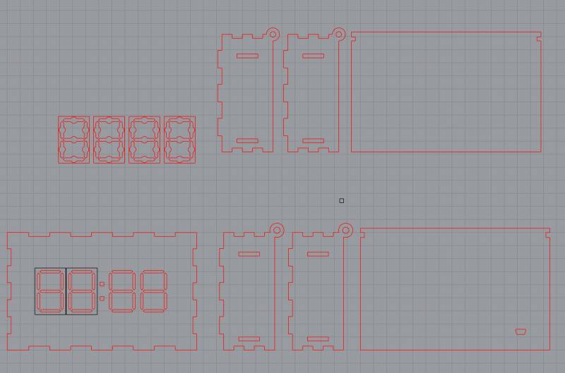
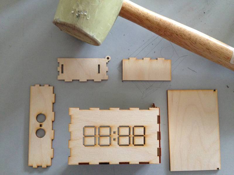
And here are pictures of the parts being cut and assembled at different stages:
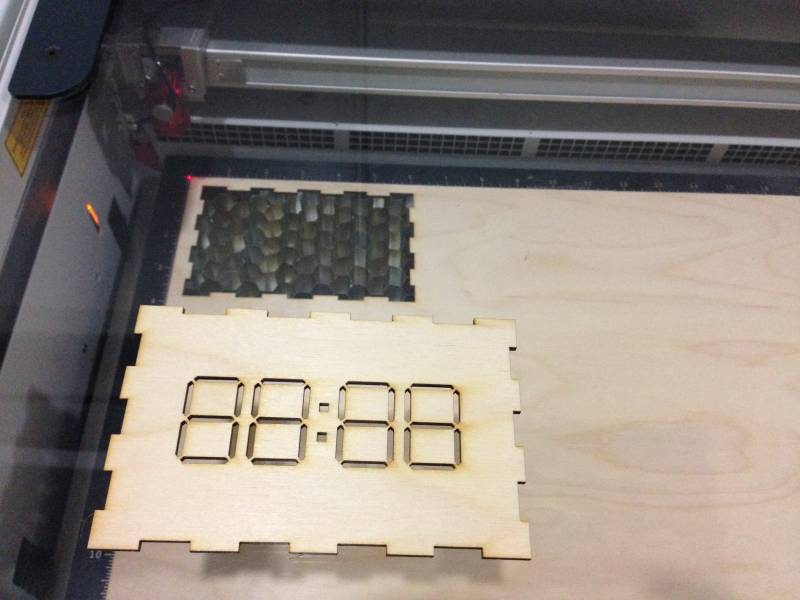
Fri, 3rd Jun
I started off the day assembling the cut pieces from last night. Most of the pieces snapped in correctly except for the loop that supports the back cover. The dimensions for it were wrong.
I redesigned it and and also designed placeholders for the digit so that the LEDs would be aligned properly. Here they are being placed on the inside of the front cover:
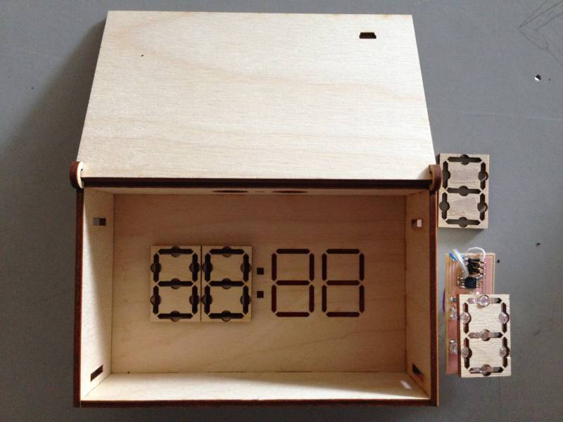
The 2 pairs of notches on the side faces are for shelves that would support all the electronic boards.
I also made a cut for the mini-usb receptacle.
The digit segments are cut out of red-coloured 3 mm acrylic.
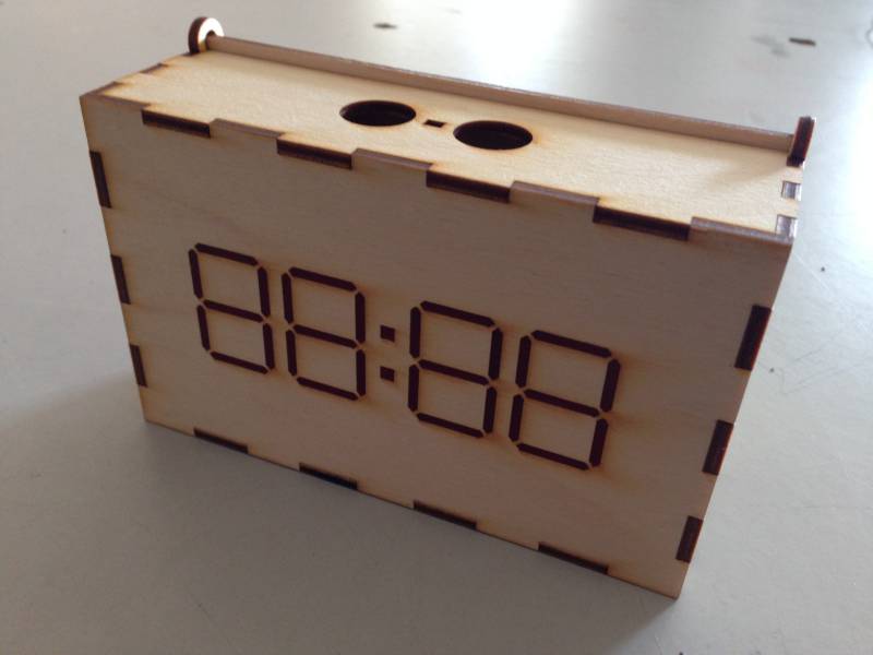
Here is the fully assembled clock cover:
Board Production
The final stretch is producing the remaining boards: controller and 3 digits.
- Make the digit boards
- Test using the Arduino and all digits connected in parallel
- Maybe test all other components together
- Design the controller
- Make it (have enough time to spare to iterate once)
Sat, 4th Jun
Today I have to finish all my remaining tasks so that I can fly back to Bangalore tonight at 8pm. Here’s whats left to do:
- Test 3 digit boards hooked up in parallel to 3.3 V
- Fix new boards jumper wiring, program and test
- Design schematic and layout for controller, mill it, stuff it - 4 hrs
- phototransistor
- 5V VR supply, VCC to other boards
- 3V VR supply to digit boards
- Comm lines to all boards
- ISP header
- USB
- Program it with all components hooked up - 2 hrs
- Produce board for USB receptacle - 1 hr
- Engrave Hi! Time logo on back cover
Jumper wiring on boards
Soldering the jumper wires was taking me too much time. I requested Ajith to help with this so that I could start soldering the remaining boards in parallel. Initially I had connected the jumpers on the back of the board, using a lead which was soldered on the front. Ajith recommended soldering the wires directly on the front.
Thanks Ajith for helping with this, I wouldn’t have been able to complete my tasks by the evening otherwise.
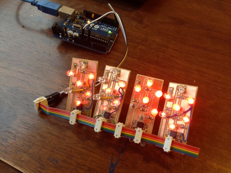
Test digit boards
I hooked up the digit boards using a 6-wire “bus” with IDC headers. 2 of the boards worked fine. The other 2 were not displaying the E and F segment. I need to debug this.
Controller Board Production
I then designed the schematic and layout:
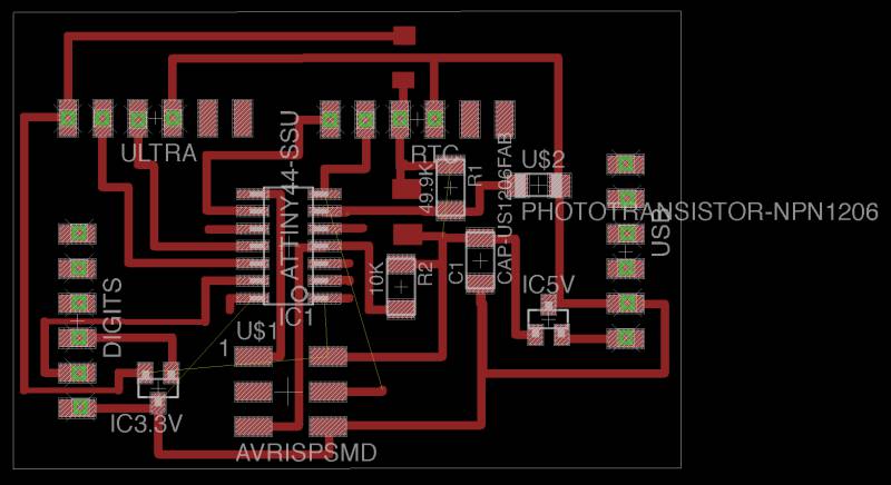
Here is the board:
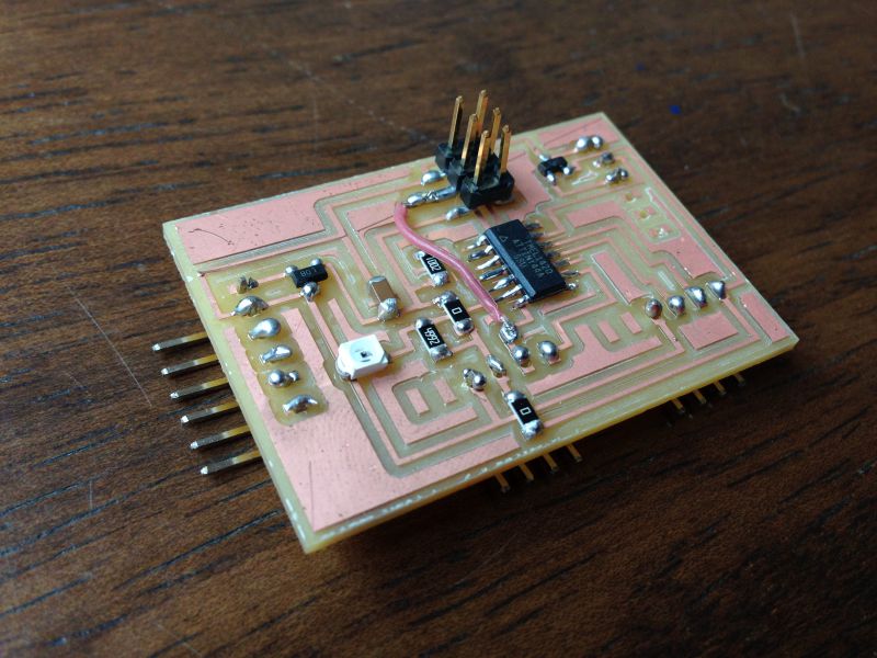
The board wouldn’t get programmed.
Looking carefully I realized there were no connections to the VCC and GND pins. I had missed adding a net to them in the schematic on the ATtiny44! I’ll add some jumper wires to fix this.
Thu, 9th Jun
I’m back in Bangalore. I’ve ordered a soldering kit and multimeter yesterday and it should be arriving today.
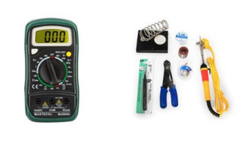
I’ll work on my pending assignments for the past weeks until this arrives.
Mon, 13th Jun
I used my new kit to solder the VCC and GND pins which I’d missed connecting.
Thu, 16th Jun
Today I’ll be debugging the digit boards that aren’t working fine.
The first one labelled “C” has the following problems:
- segment E doesn’t light up I checked the LED with a 3V cell, and it doesn’t seem to be working. I’ll need to replace it.
- segment A and G go off intermittently. Pressing LED D seems to light up A & G. This seems to be due to a loose solder contact on LED D, which is shared between LED A, D, G. I’ll need to resolder that joint.
For the 2nd board, labelled “A”:
-
A, E, F segments aren’t working
-
A has a loose contact, needs to be resoldered
-
E & F are working when tested with a cell. Also when F is powered by a cell, E lights up too.
- This was due to a cut trace - the same one which connects E & F anodes.
Controller board, which wasn’t getting programmed:
- SCK from the IDC header wasn’t connected to the SCK pin on the ATtiny45. I think when renaming that net from SCK to SCL, the connection was dropped.
- Need to put a jumper.
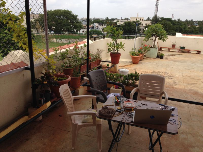
Here’s my new temporary terrace workspace :-)
Once the issues were fixed, the boards worked fine.
Next step is to program the controller and have it coordinate the activities of the rest of the boards.
I’m going to write this as an Arduino Sketch so that I can use the Wire.h libraries for I2C communication.
First, lets get the digits displaying a time.
Sat, 18th Jun
Was down with a fever for the past 2 days.
Whats left: - Debug why the controller board is getting hot - probably a short - Debug the digit boards, which display incorrectly when more than 1 digit board is hooked up to the serial bus - Program the controller to display a time on the digit boards - Program the controller to get time from the RTC - Program the controller to get data from the ultrasonic sensor - Program the controller to get data from the light sensor - Unsolder the phototransistor, solder on leads, mount it on the top panel of the clock, solder the leads to the controller board - Cut the USB board, solder the connector, solder jumpers to the controller board - Make a video - Make the presentation page
Problems with controller board - had 5V voltage regulator getting very hot, removed it.
Serial comms issues, pin had to be resoldered.
Digits work fine independently, but extra segments light up when multiple boards connected to the bus.
Mon, 20th Jun
Finally figured out the problem with wrong segments lighting up. It was because all the digits were connected by a single set of wires, like a bus, and 6-pin IDC connectors. This resulted in the signals from one of the digit boards affecting others.
The solution was to only have the VCC, GND and MISO pins connected on the digit bus.
- Program controller to get data from the RTC.
Tue, 21st Jun
0.5 - Program the controller to get data from the light sensor 1 - Program the controller to get data from the ultrasonic sensor 0 - Reflash the digits with 100ms display 1 - Mount the digits, solder leads and wires 1 - Unsolder the phototransistor, solder on leads, mount it on the top panel of the clock, solder the leads to the controller board 1 - Cut the USB board, solder the connector, solder jumpers to the controller board 1 - Make the presentation page 1 - Make a video - Update notes to show Arduino is used only for testing - Demo with Francisco
Phototransistor is connected to PA7 (ADC7).
Somehow got all the pieces soldered, mounted last night at 3 am.
Presentation done.
Wed, 22nd Jun
-
Get phototransistor working switch leads & resolder test
-
Get ultrasonic working write code
-
Program controller to turn on when off and movement detected.
1 - Make a video - clock on in daylight - gets progressively darker, until clock goes off - hand wave turns it on for 5 sec
1 - Test video conference setup
2 - Update presentation - add networked, custom LED details
- write script for 2 min presentation, practice demo with Francisco
Ultrasonic
Trigger is PA1, Echo PA2.
Presentation
It all finally came together a few hours before the presentation.