Electronics production
Assignment
- Make the FABISP in-circuit programmer.
Milling preparation
In the beginning I wanted to make Andy's ISP because I already made Fab ISP before in training for fab lab managers, but then I did not document the process. I quickly changed my decision when my instructor told me that I probably did not have all the components to do that in my lab. We just recently installed the electronic workshop in our lab (Fab Lab Hornafjordur) so making circuits board on our own is very interesting. I decided to use Neil’s Fab ISP and started to prepare.
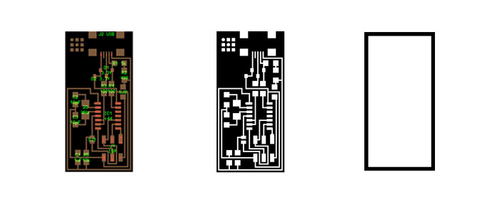
I downloaded these PNG pictures from the Fab Academy home page . They can be found in the last paragraph under "assignment". I did use the two black and white PNG high resolution pictures to mill out my board. The colored picture is from the software Eagle and I assume the drawing is made in that program. In this lesson we don´t draw up the board from scratch but we will learn that later.
Milling
Software used: Fab Modules
Machine used: Roland MDX 20
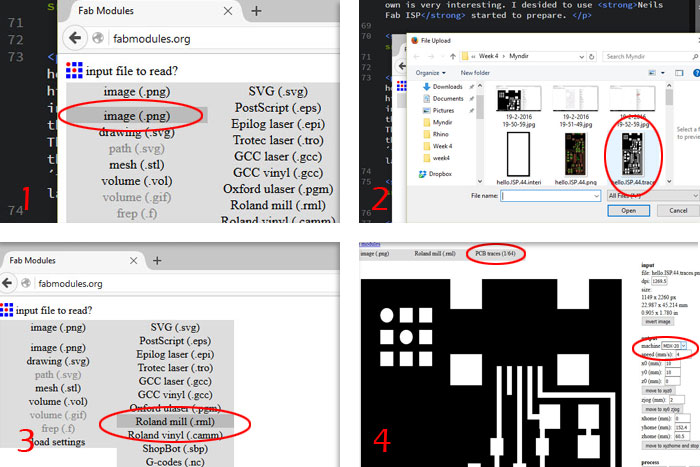
Picture 1: In Fab Modules.org I started to click on the gray button "Input format" then I clicked on "image(.png)".
Picture 2: Then I selected Neil’s PNG file called "hello.ISP.44.traces.png". This file will mill out the boards traces which is the first step of two step milling.
Picture 3: Most labs are using the Roland milling machines so I selected "Roland mill (.rml)" that led me to the next process.
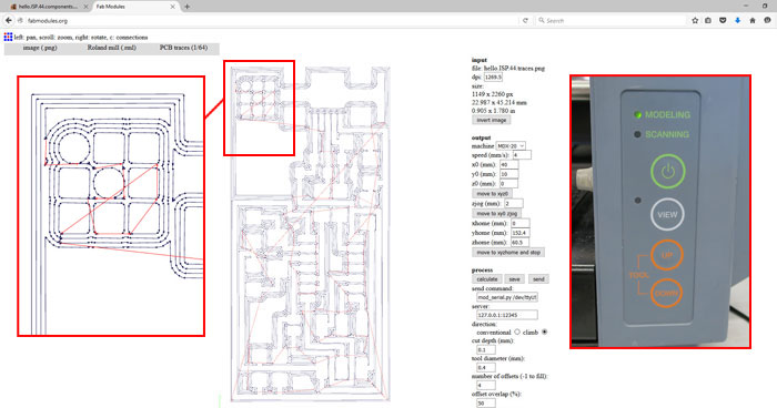
Picture 4: In process window I chose "PCB traces (1/61) but that is the size of the milling bit I will be using. Under "output" I needed to choose which Roland machine I was using. In my lab we have MDX-20 Roland Modela so I picket that one.
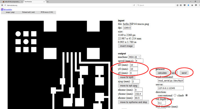
When I had selected MDX 20 the next step was to find my zero point where I was going to locate my board on the PCB plate. I only needed to change "yO(mm) coordinates to 35 mm because it was not the first project cut out on that PCB plate that I was using. After zeroing X and Y axes I needed to zero the Z axes but I did that little later. Then I hit "Calculate" button to see how the traces would turn out (picture below). So mostly I used the default settings and you can see the "cut depth" is 0.1 mm (marked with red ring on the bottom of the picture).
For zeroing the Z axes I already had set the (1/64) milling bit high into the collet, so I needed to hit "View" button on the Modela and then hit "down" button to lower the collet. When I had about 5-8 mm from the tip of the bit to the top of surface of the PCB plate I stopped hitting the "down" button. Then I untighten the milling bit (screw in the collect) until the milling bit touched the PCB plate. I had to be careful because these small size milling bits are very fragile. Then I tightened the screw that holds the milling bit again and Z axes was zeroed. After this process it´s important not to use the "move to xyz0" button but it’s possible to use "move to xy0 zjog" button for movement. Then everything was ready so I could hit the "send" button and the Modela started to mill.
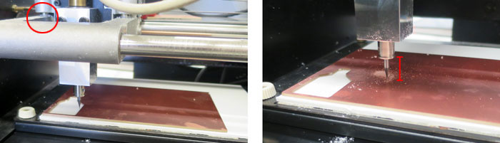
I soon found out that the milling bit was not milling deep enough and something was wrong. To fix that my first thought was to dial in deeper "cut depth" from 0.1 mm to 0.2 mm but my instructor told me through Hangouts that the collect was to low (see picture) so the machine could not mill further down after zeroing the z0 axis. To fix that I pushed the View button on the Modela and Up button and collect went higher. Then I set the z0 axis again, this time milling bit sticking further out from the collect. I tried to start milling again but soon found out that I needed to reset the machine. To do that I did hold down the "Up and Down" buttons until the light started to blink. It took 40 - 60 seconds for the machine to reset.
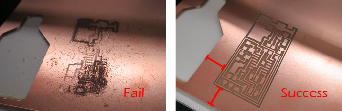
As you can see on this pictures the milling bit did not cut through the copper layer and this first attempt was a failure. But after putting the collect in higher position, lower the milling bit, resetting the machine the Modela made a beautiful traces. I could though save more material with more accurate X and Y coordinates.
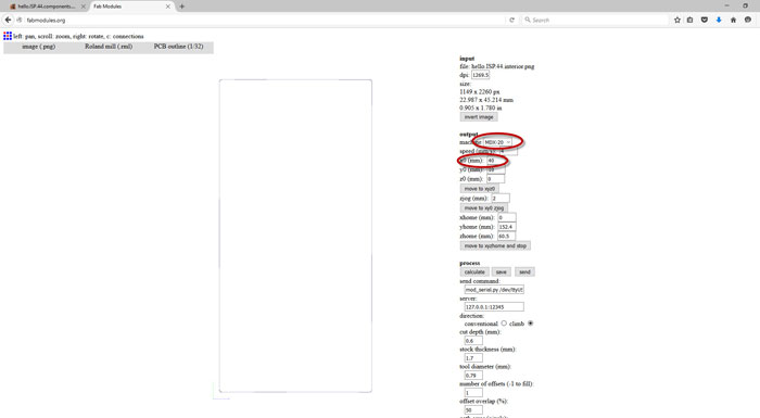
I did the same process to cut out the outline of the board. I used the other PNG picture: hello.ISP.44.interior.png but under "process" I had to select "PCB outline (1/32)" a thicker milling bit for cutting.
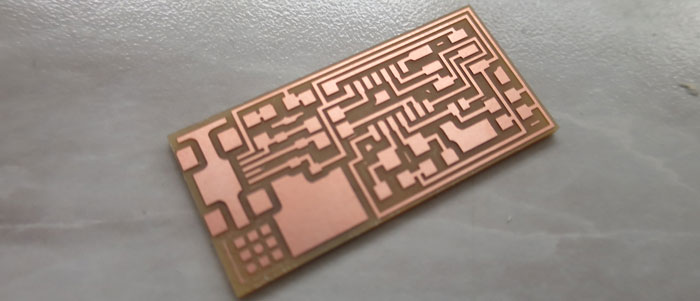
The board looked great coming out from the Modela. It was a little tricky to remove it from the sacrificial layer because of the double sided tape underneath.
Soldering the board
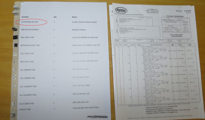
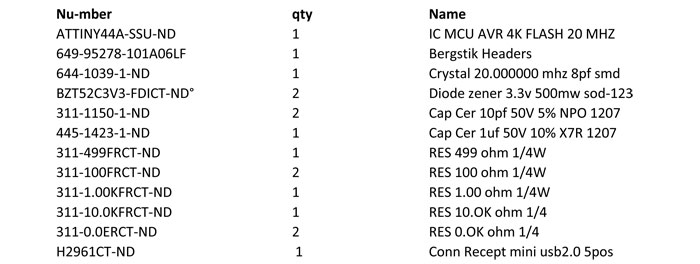
Like I said before I had made a list with all the components from Digi-Key Electronics and Mouser Electronics that is needed in this ISP. I printed the list out and put a tape underneath the left side so the small components would stay in place. So everything was organized BUT I soon found out that we did not have the ATtiny 44 microcontroller in our Lab, somehow it did not arrive with the Digi-Key Fab inventory order. This was unfortunate because our lab is more than 500 km from FAB LAB Reykjavik and I knew I would have to wait a while for the microcontroller to get here. But no need to panic, especially because I had made a Fab ISP before.
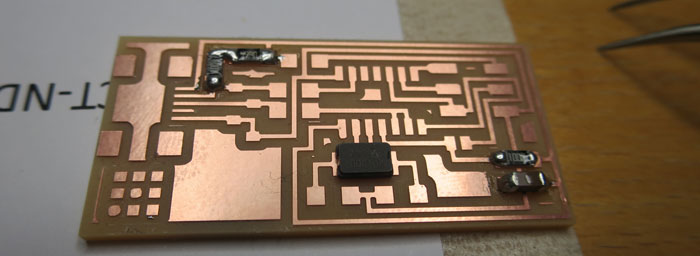
So I started to solder the components on the board.
A magnifying loop was helpful to see what I was doing. The process was slow because I wanted to do a proficient job.
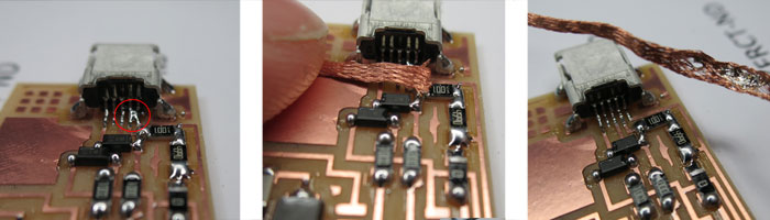
It was little tricky to solder the USB connections to the footprint, it´s very small. I used the method that Neil described in his lesson. Put a solder all over the connections then use a Quick Braid wire and lay soldering iron over the wire and heat up the soldering. Remove the wire when it´s hot and unwanted soldering between connections will be gone.
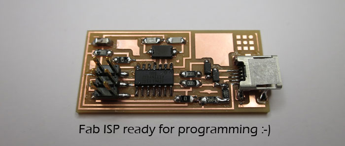
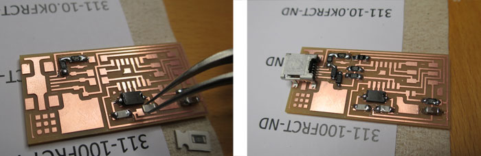
After few days of waiting for the microcontroller I could finish the soldering and start to work on the programing.
Programing
I started to find me a lesson on how to do this and I have to admit that I ran into few problems. The lesson is from Fab Academy 2015: FabISP Programming To program the microcontroller I needed to set a starting program on the chip. I needed to communicate with it and I had two options. Use AVR programmer or use my Fab ISP that I already made before Fab Academy. I chose to use the one I made and started to go over all soldering on the new board. I also took a Multimeter and did an inspection. Everything looked good so I plugged it with an old laptop that I had in the lab. The laptop did not complain and the board did not burn. I followed the programming instruction given on the tutorial page, starting with installing the necessary software for my operating system.
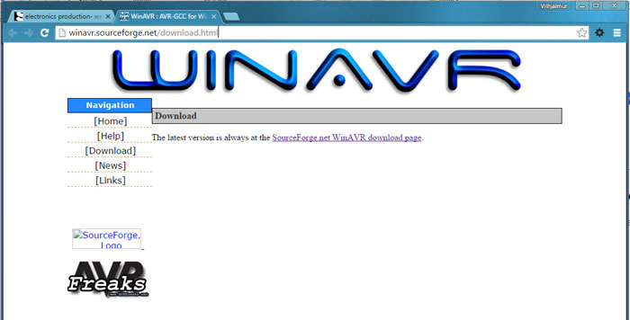
I downloaded WinAVR compiler I copied the Systems Path Variable on my computer before setting up the WinAVR compiler. Unfortunately WinAVR is no longer supported and it can destroy that part.
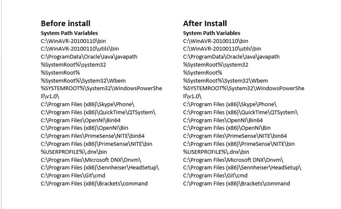
I was lucky the program did not make any changes on my Systems Path Variable so I continued with the process.
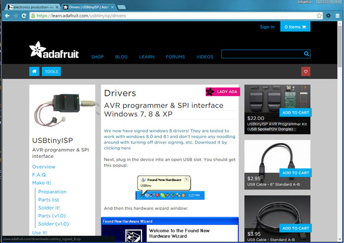
Next I needed to install drivers for my version of Windows which in my case is Windows 10. I found them in the Fab ISP Programming lesson (link above).
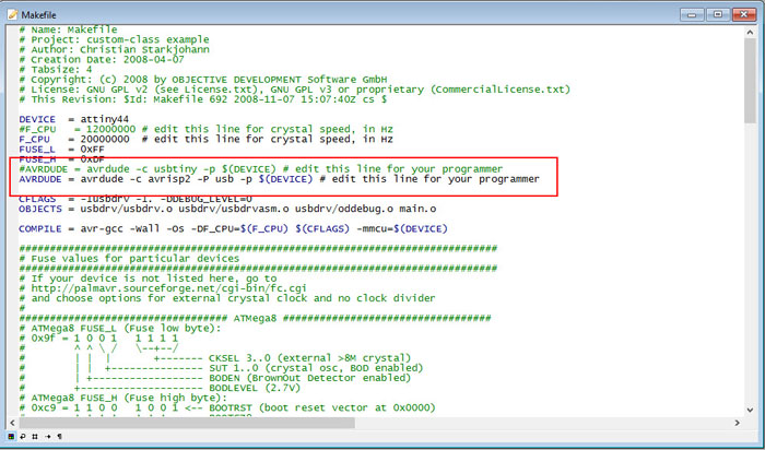
Next move was to change the MakeFile (see lesson). I opened the MakeFile in Programmers Notepad that came with WinAVR. I needed to take the hashtag from the "AVRDUDE .. avrisp2" and put it on "AVRDUDE .. usbtiny" command line (see picture), then hit save.
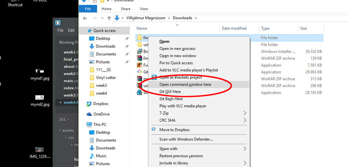
Next process from the lesson was to open a command window. To do that I had to hold down the Shift button and right click on the FirmWare file (which I downloaded, see lesson). Then followed the lesson for further instructions.
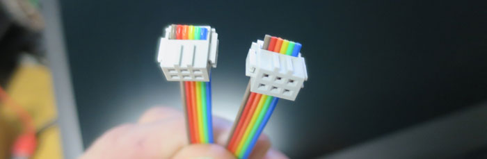
In the process of programming the chip my instructor found out that I did not turn the connectors face in the same direction. The two 6 pin connectors has two ridges on one side and that should always face microcontroller. When connecting two boards together; the same color wire needs to go on the same pin on both boards, very important.
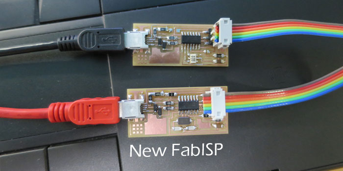
I ran into other problems in the installing process, related to my old Fab ISP. But after making that board I did not disconnect the JS1 and JS2 resistors after programming, so when trying to program the new board my old board always reset itself. I disconnected the resistors and the old FabISP was up and running. Then I forgot to power up the new FabISP with a USB cable, but the old one was hooked up with power but that was not enough. When I connected the new FabISP all commands ran smoothly and I had successful install. I disconnected the old FabISP and opened "Device Manager" and found my board under "libusb-win32 devises" That means I have a working FabISP.
Related links
FabISP ProgrammingAVR Setup
Microcontrollers - A Beginner's Guide - AVR (WinAVR) Programming Environment WinAVR