Week 2 Computer-Aided Design
Assignment
- Model (draw, render, animate, simulate, ...) a possible final project.
- Post the work on the Academy class page
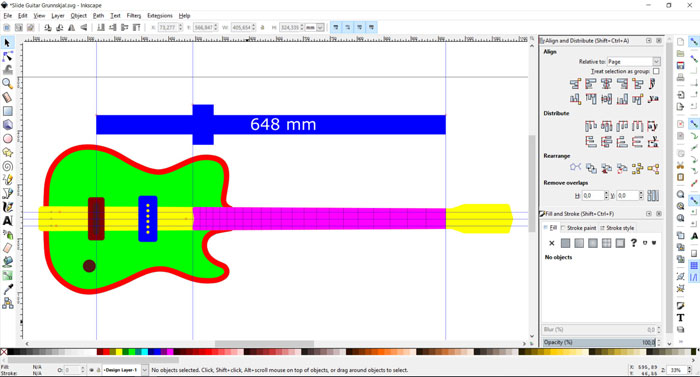
I decided to draw up the final project guitar in 2D first and use Inkscape. I specially wanted to focus on the neck and the scale size. I tried to follow the raw sketch that I made when I was shaping the guitar. Like I said in the introduction the guitar is based on an old cigar box blues guitar design, where the neck is in one piece and goes through the box. In this first drawing I didn't want to think about where to put the electronics, just draw up the basic shape of the instrument.
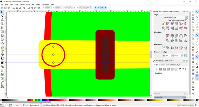
At this stage I was not sure where I should locate the holes where the strings go through the neck behind the bridge. Normally the strings do not go through the cigar box on this kind of guitars. On this drawing I located the holes where they need to go through the body. This may change in the design process.
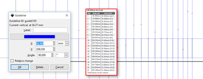
For the frets on the neck I needed to decide the scale length. I decided to have 21 frets and use the scale length of 648mm. I made a new Inkscape document and used the guideline tool to set each fret in exact dimension. I used on-line Fret position calculator that is on the Stewart-MacDonald web page.
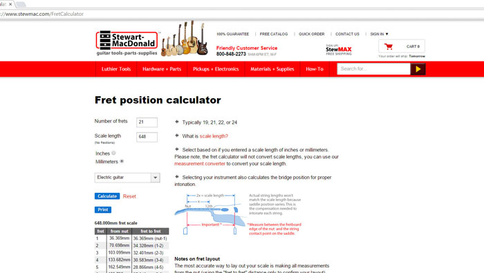
Stewart-MacDonald is a huge guitar parts- and guitar making tools supplier. StewMac, as I like to call them, are highly innovative company and I always look forward to see their catalogue that they send out frequently, always some new designed tools or guitar related items. I will need to order few parts from them for this project that I will not make myself, like tuners, pots and the P90 pick-up.
From 2D to 3D / Rhinoceros 5
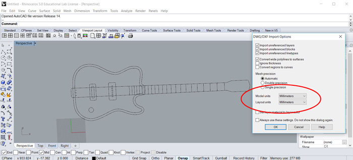
When I had combined the two Inkscape documents into one I exported the file as a DXF document. I decided to use the program Rhinoceros 5 for the 3D. It can read DXF format so it was no problem to import the 2D from Inkscape. It´s important to use the same "Model units" as you use in your 2D vector program, in my case I used mm, if not the size of the model will not be the same in Rhino.
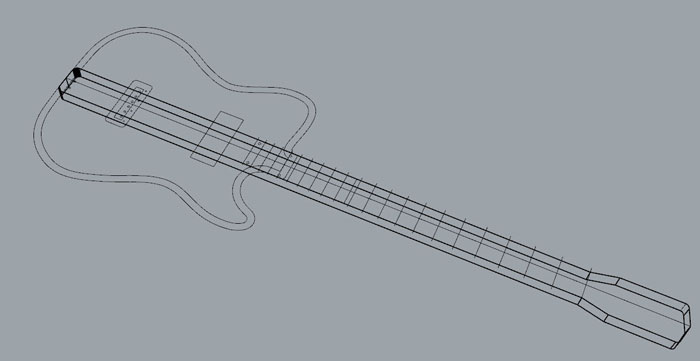
First task was to work on the neck. I needed to pick the shape of the whole neck and use the command "PlanarSrf". Then I needed to click on "Solid / Extrude planar curve / Straight " in Rhino´s top task bar and set the height to 19mm.
I wanted to extrude the shape of the body, but it was not the right time for that because I did not know the thickness of the neck. I decided to work more on the neck for that reason.
I had to make the neck thicker for a while and then cut off what was needed to cut off in a sequel of actions.
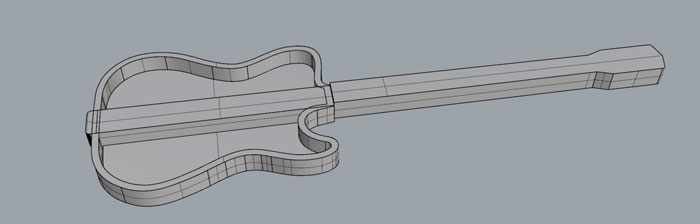
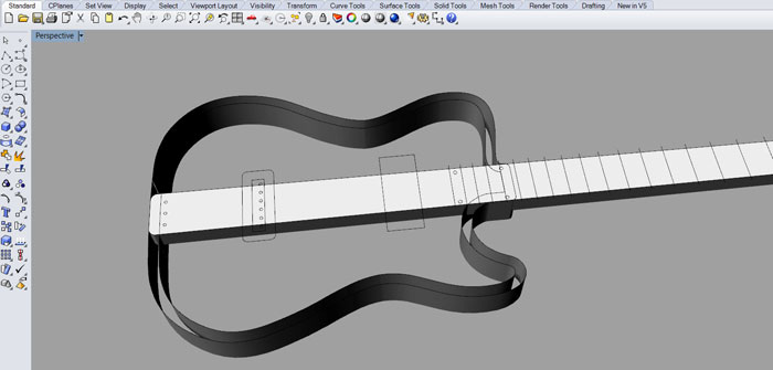
I used "Solid/Difference" to cut off the part of the body where the neck goes through, because the neck is one piece. As you can see on this picture there is a plenty of room for electronics. In this round I have not cut the hole for the p90 in the neck. That comes later.
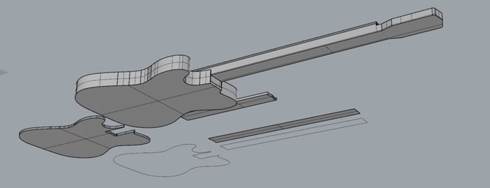
I worked on the fret board and also on the front plate that equals the cover of the cigar box. The main shape of the guitar is coming together, but a lot of work is still left shaping the neck.
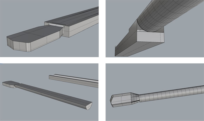
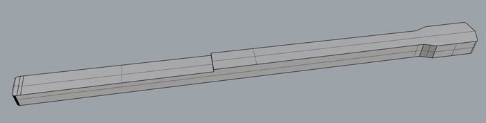
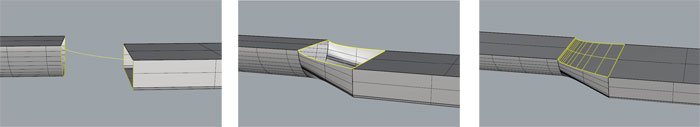
I decided to split the neck in two parts and keep on shaping it. I first tried to use negative form to difference it from the box shape I had made. That did not work out so I made the round shape using "Sweep 2 rails tool" . That tool was also very helpful when shaping the connection between the headstock and the neck. This first connection was not perfect, especially because the headstock was 2 mm too thick.
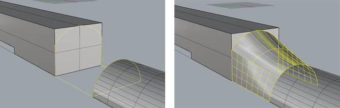
When I started to connect the two parts of the neck together I used the "Sweep 2 rails tool" but first I needed to draw curved lines on the back shape of the neck. Regarding the connection I had solid shape (the round neck) but no curves or lines for connection, so I needed to run the command
I made a new connection between the neck and headstock with the same Sweep 2 rails method.
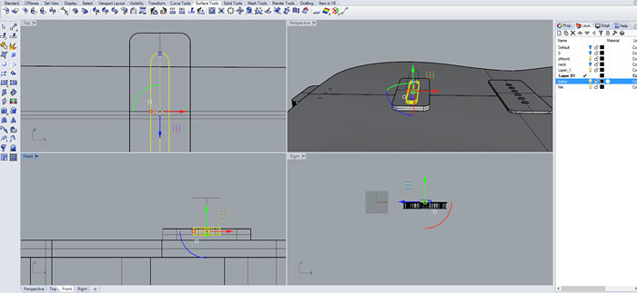
I drew up the P90 pick-up and the bridge. The drawing of the bridge is just temporary, I am not sure how it will turn out in the end.
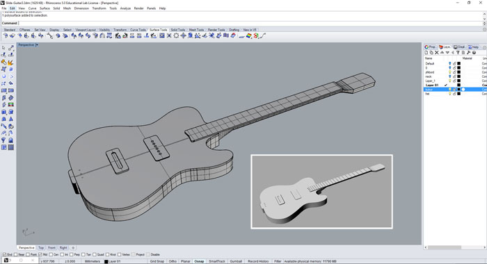
Now this first 3D sketch is ready of the Blues Slide Theremin Guitar. I have not decided any location for electronics. It´s just mostly the basic shapes of the body and neck of the instrument. In the lower left corner is a rendered image of the 3D drawing.
Grasshopper - algorithmic modeling for Rhino
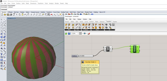
Grasshopper is a visual programming language developed by David Rutten at Robert McNeel and Associates. Grasshopper runs within the Rhinoceros 3D CAD application. Programs are created by dragging components onto a canvas. The outputs to these components are then connected to the inputs of subsequent components (wikipedia.org). After a download from the Grasshopper home page it was an easy plugin to install. I tried to start and make something myself but I was quite lost. I did make this sphere but I did not understand what I was doing. I needed a lesson.
So I started to look for some good beginners lessons and found one from YouTube. Intro to Grasshopper for ID . The main goal for the lesson is to make a shelf and in the same time learn some basics in Grasshopper.
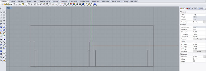
First task in the lesson was to draw curves. The biggest curve is for the shelf itself, but the smaller ones are for legs/sides and finally support for shelves. I needed to group all legs together and all support as well.
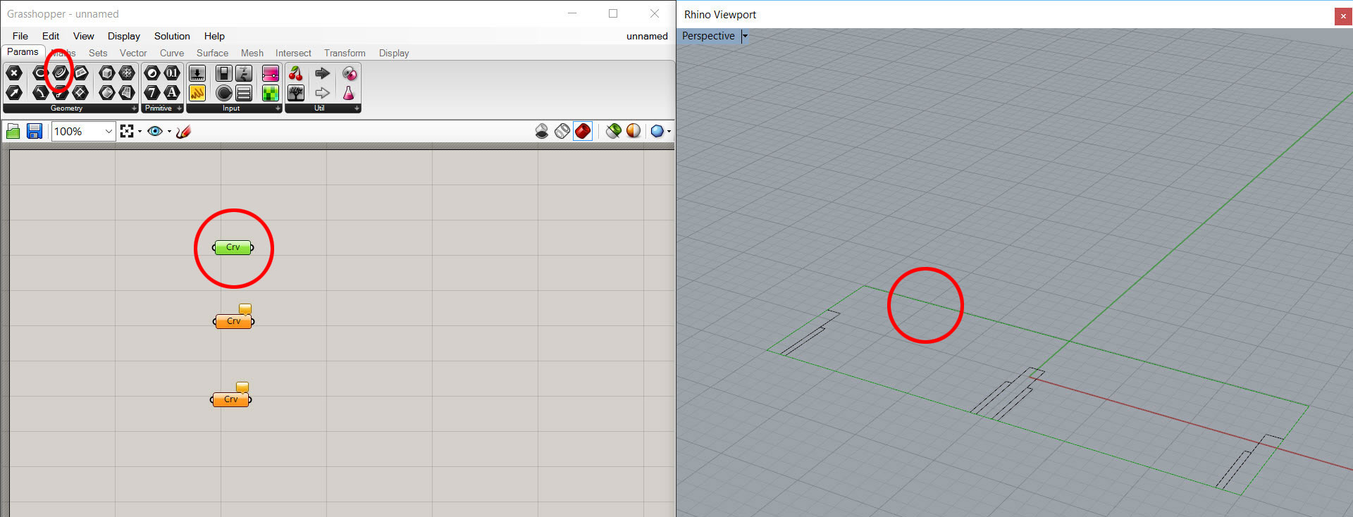
Under the "Params" tap I found my first component called "Curve" (see picture) to drag into the canvas. I needed to connect this new components to the curve lines that I had made in Rhino. I right clicked on the component and clicked on "Set one curve" then I needed to go to Rhino and click on the biggest curve and then my first connection was made in Grasshopper. For the next two curves the legs and the support I did similar process but both of them were grouped in Rhino, so I right clicked on the "Set Multiple Curves" to get the right connection for grouped items.
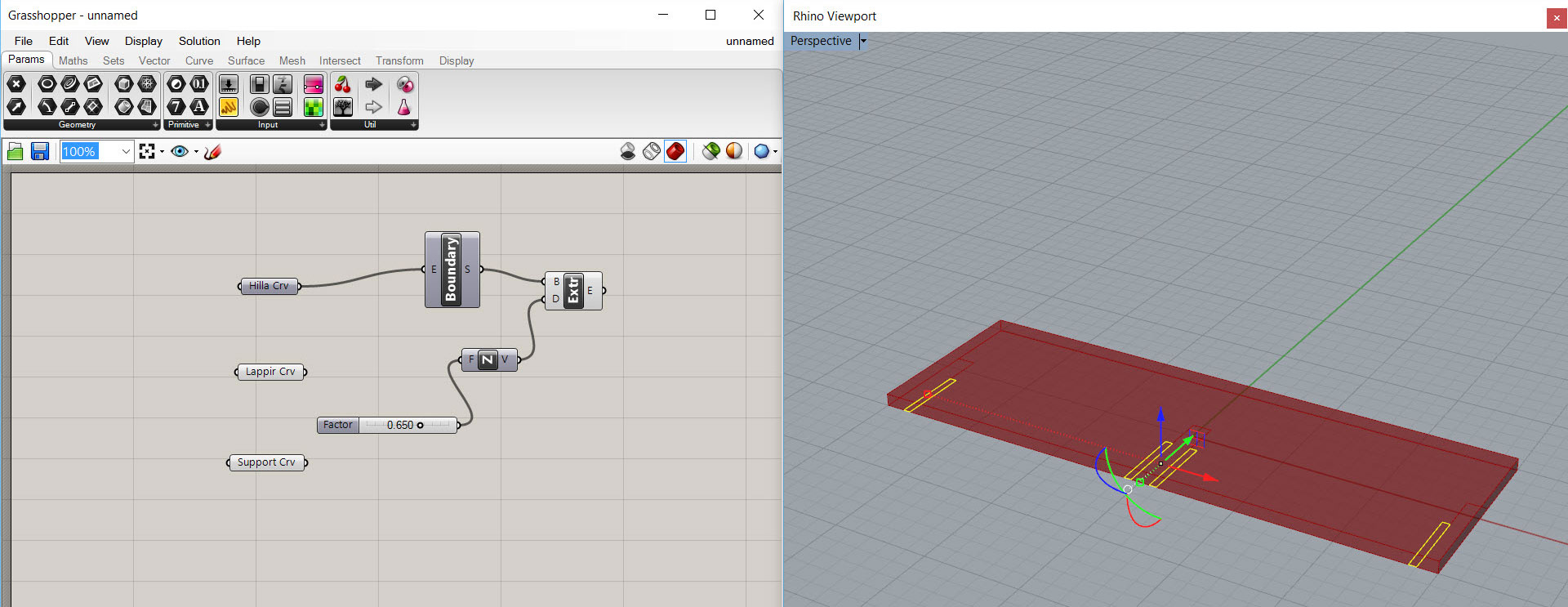
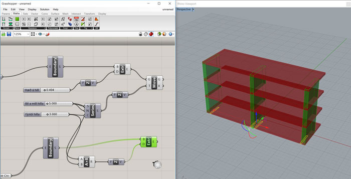
I kept on following the lesson and added those components you see in the picture. I had trouble with the "Boundary" component because the name was not the same in my version of Grasshopper and in the tutorial. The name used to be "PlanarSrf" but the icon was the same on the button so I could figure it out. The extrude component gave the surface and thickness, followed by a "Number slider" to control the thickness.
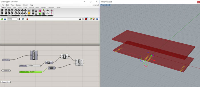
Then I added "Movement" component and another "Number slider", and more shelves started to appear. Now I could control the height between shelves. At this moment I started to fall in love with Grasshopper, what a brilliant program.
Next mission was to start working on the legs, the vertical elements for the shelf. Good thing about Grasshopper is that you can copy a group of components and paste for reassembling. To get the height of the legs right I needed to add some simple mathematics (space between shelves X number of shelves. So I added "A x B" component that I connected to Space between shelves number slider and Number of shelves number slider.
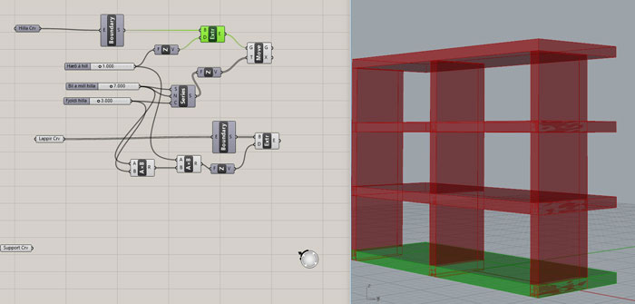
I did not want the legs to go through the top shelve (Revers in tutorial) so I added another ""A X B" component in front of the other ""A X B" and the height of the legs got in the right position. Then the bottom shelf was hidden by right clicking on the first "Boundary" component and pressed "Spacebar". Then a special window opened and I clicked on the “hide” icon, bingo the bottom shelf was hidden.
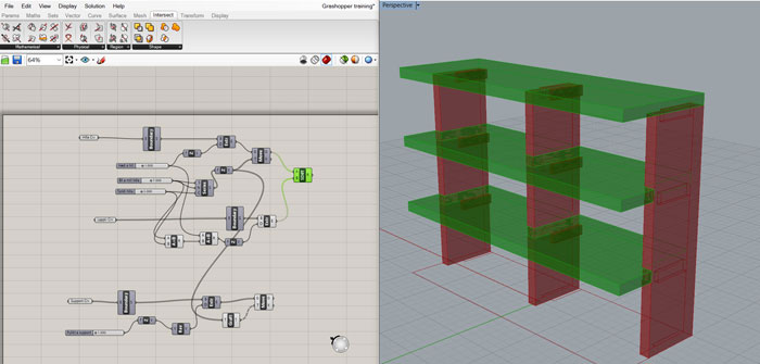
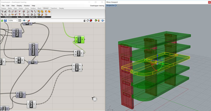
Next move was to work on the support for the shelves. It was quite complicated because there was a component called "Graft Tree" and another one called "Reverse" that was needed to link for a right alignment of the support.
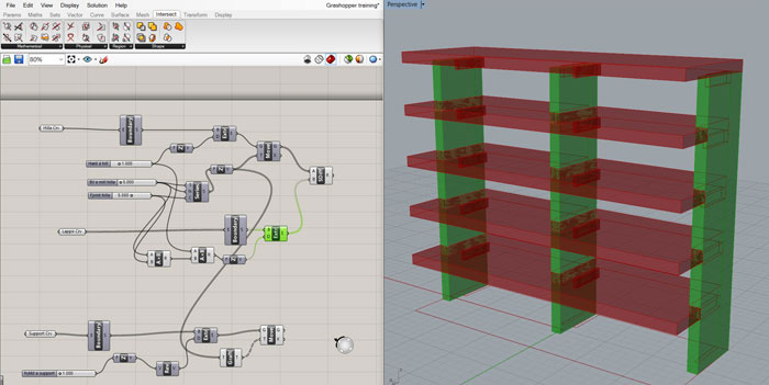
Then it was time to play around with the Number sliders and resize the shelves or add more shelves.
It’s also very good to be able to go back to the curved line and change it in Rhino. In the same time all shelves will change. This gives you a great control of the size of all shelves.
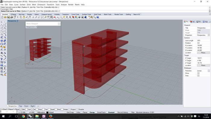
A nice feature is put a radius on one of the corners with the "Fillet" command. I was still working with the first curve at the bottom of the drawing and as I changed the curve all the shelves changed automatically.
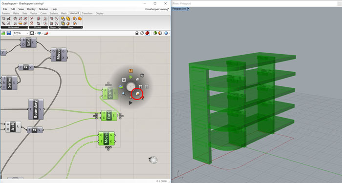
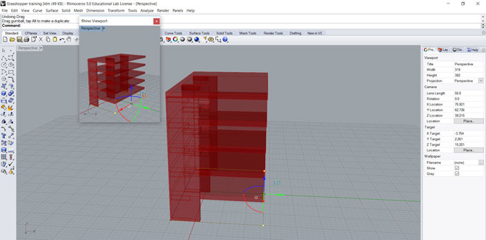
Then I needed to "Bake" the three outputs in Grasshopper to be able to work further on some details if needed in Rhino. So baking the outputs changes the Grasshopper drawing into a normal Rhino drawing. To find the "Bake" command I selected the tree outputs and right clicked and hit spacebar. Then clicked on the egg icon (in the red ring).
This is how the drawing looks like when you have run the "Bake" command. The Grasshopper drawing is still inside the Rhino drawing so best way to separate them is to right click on each output and "Enable" all of them in Grasshopper. Then the baked Rhino drawing is free from the Grasshopper output.

Good thing about Grasshopper is that you can always go back and mess with the Number sliders and "Bake" the outputs again. I think Grasshopper can give me a lot of opportunities to make 3D drawings. I fear one thing though, in big drawings the canvas can be way to complicated, like a big wire mess. I think it will be very interesting to take more lessons in Grasshopper and learn more about it.
Related links
Inkscape Written Tutorials Inkscape Video Tutorials
Rhino Lessons
Grasshopper Tutorial Beginner
Intro to Grasshopper for ID