Input devices
Assignment
- Add a sensor to a microcontroller board that you have designed and read it
This was one of the week assignment I was looking forward to because finally I could do so some testing with photo transistors. I started to read few Fab Academy pages where previous students worked with the Hello light board. The basic Hello light board has one Photo transistor named "Photodarlington NPN CLR PLCC-2".
For my final project I want to add 4 - 12 Photo transistors inside the neck that can read light from my glass slide. One thing is sure I cannot let all those photo transistors be sending signal to the main out-put of the guitar at once. That would be too much sound madness. So I want to test if I can get a signal from one phototransistor at a time, the phototransistor that is reading the highest amount of signal or light.
Before I could start doing those tests I needed to draw up a Hello Light board and add at least three photo transistors to it. Mill the board with our Modella milling machine and solder the components. Program the board in "C" and read the signal with the Python program that Neil talked about in his lecture. That was my plan for this assignment.
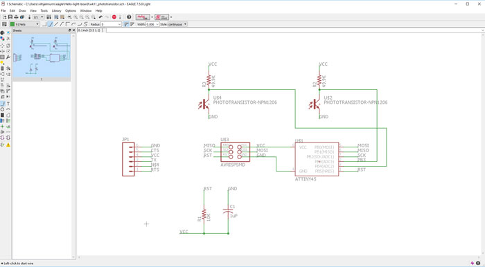
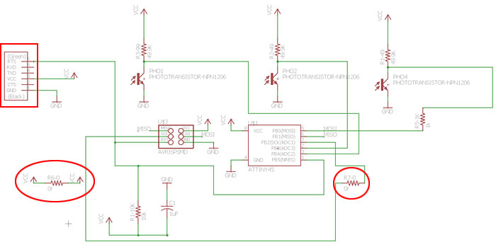
I downloaded the schematics for the Hello Light board and started to change it. I added one more photo transistor and to my surprise all pins were occupied when I wanted to add another one. I thought to myself the Attiny 45 is a small microprocessor and will not give me an option to add more than two. My instructor told me I could use the programming pins SCK, MISO, MOSI if I only added a (1k) resistor between the programming lines and the photo transistors.
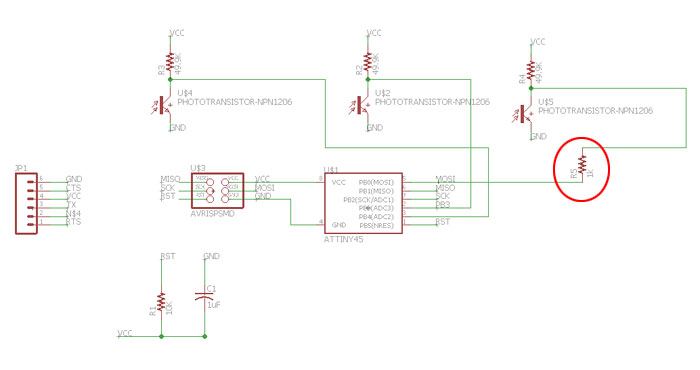
I added the 3rd photo transistor and the 1k resistor. I was ready for the next step, to draw the traces.
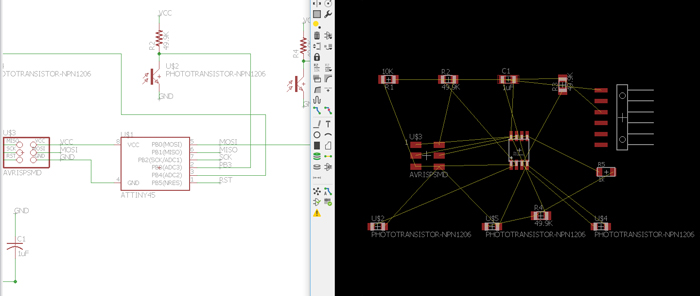
It was clear that I would spend some time making the traces because I had added these extra components. Yellow Ratsnest lines where crossing all over the board. It was helpful that I made a good Eagle documentation in the 6th week.
I tried few ways to draw the lines but in every atempt I ended up with one line that was impossible to close.
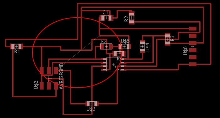
Finally I could close the puzzle but there was one problem, to many traces inside the AVRISP-SMD footprint. It was clear I could not do this properly without using jumpers. To do that I needed to change the schematics.
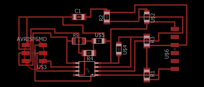
Before I added the jumpers I ran a Tools/DRC check and got a complain about the header for the TTL-232R USB cable. I changed the connector to the same one I used on Hello World board the FTDI-SMD-Header. I added one jumper to the VCC line and another jumper to the SCK line. Now I just needed to finish the traces.
Finally I was ready with the traces and no errors where bothering me in the DRC check. The names of two photo transistors where sticking out so I needed to delete it, using the Smash button.
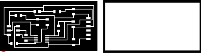
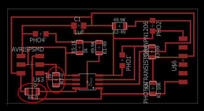
PNG photos of the traces ready for the Fab Modules and the Modela.
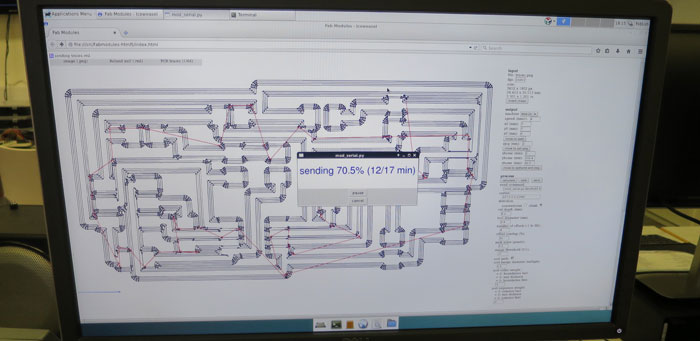
I ran into small problem with Fab Modules, the browser could not connect to server: 127.0.0.1:12345 and computer was not sending data to the machine. My instructor reminded me I was not running the node server, problem solved I could mill the board.
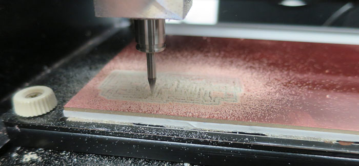
The 14 year old Roland Modela milling beautiful traces.
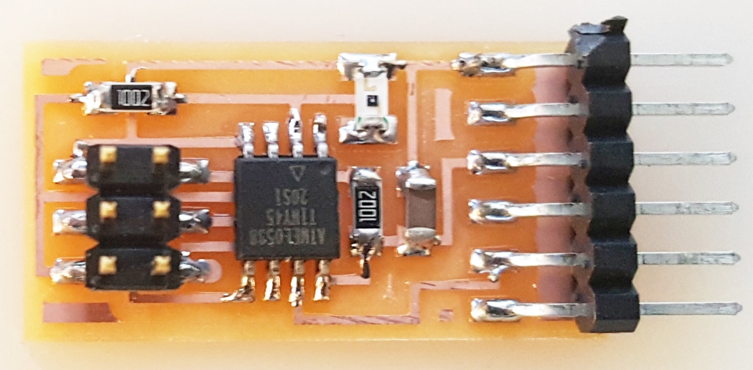
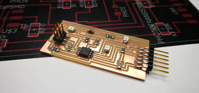
When the machine was milling I collected the components for the board:
(1) Attany 45 microprocessor
(3) Photodarlington NPN CLR PLCC-2
(3) Resistor 49.9k
(1) Resistor 10k
(1) Resistor 1k
(2) Resistor 0 (jumpers)
(1) Capacitor 1uF
(1) FTDI-SMD-Header
(1) AVR-ISP-SMD 6 pin connector
When I had finished soldering the board I needed to take a look at the programming part. I was not going to jump into it right away, I would need to do some studying.
Programming the board
I started to read many Fab Academy student pages and I tried to program the board without getting any help from my instructor. I got to admit I could not get far. With some help I finally got back on track but it was not an easy process:
1) I downloaded the hello.light.45.c file and the hello.light.45.make file from the Fab Academy page. I made a new folder in C://user/vilhjalurm/eagle/Hello-light-board/programming_files and put the files in the new folder. I did NOT have to change the C file or the Make file.
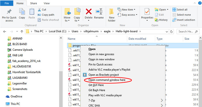
2) I right clicked on the "programming_files" folder and held down the Shift key and clicked on "Open Command window here".
3)
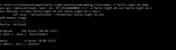
This is what came up in the command window: C:\Users\vilhjalmurm\eagle\Hello-light-board\programming_files>
I added this command:
make -f hello.light.45.make and hit enter. Now the program has made an hex file.
4) I connected the Fab ISP and the new board to my computer with USB cable and the TT-.
232R-3V3 cable. No bad response and I could go on.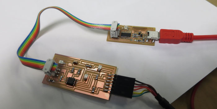
5)
Next move was to make fuses with this command:
make -f hello.light.45.make program-usbtiny-fuses. When I hit enter I got this error: *** No rule to make target `program-usbtiny-fuses'. Stop. Since there was nothing about fuses in the Make file this error was OK I could take the next step.
7)
Now I wanted to let a Python program read a signal from one of the photo resistors. I downloaded this file
hello.light.45.py - Right click to download
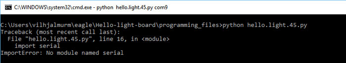
from the Fab Academy page and put it in the same folder as the Make and the C file. I opened a new command window and right clicked with shift button down on the programming_files folder and wrote this command: python hello.light.45.py.
Then I got this error: ImportError: No module named serial. This meant I had not installed Python serial.
I googled Python Serial and found it on Git: PYSERIAL and got this command install link: pip install pyserial. I tried the command and got this error: 'pip' is not recognized as an internal or external command,
operable program or batch file.
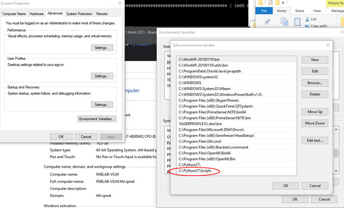
OK this was not going in the right direction but patience, yes patience works. My instructor told me I needed to add "Python Script" in "Systems Path Variable". I used this lesson to do that:
How to add new system path variable in Windows 10
In Search, search for and then select: System (Control Panel)
Click the Advanced system settings link.
Click
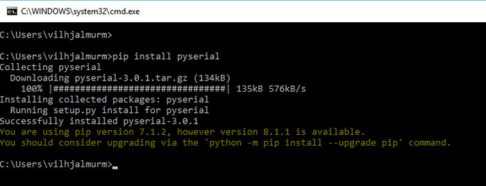
Ok now I could run the Python Serial install command without errors in a new command window: pip install pyserial
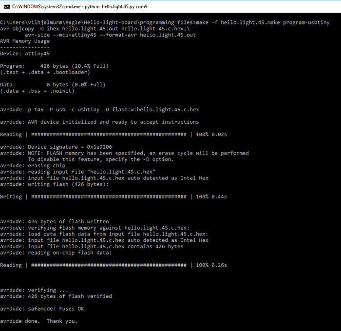
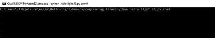
Now I had everything up to install the hello.light.45.py program, so I went to my previous command window and ran this command: >python hello.light.45.py again and it worked.
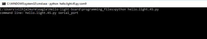
8) In this last step I needed to tell the computer what serial our new hello light board is using. To see that I opened "Device Manager".
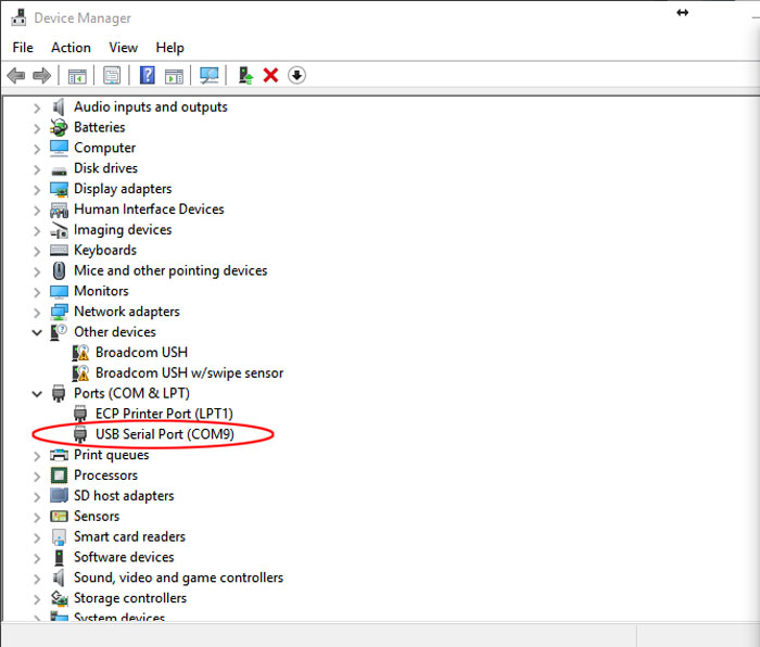
COM9 it is so back to the command window and add that.
The Python program did open but it did not read the Photo resistor and in the and it froze.
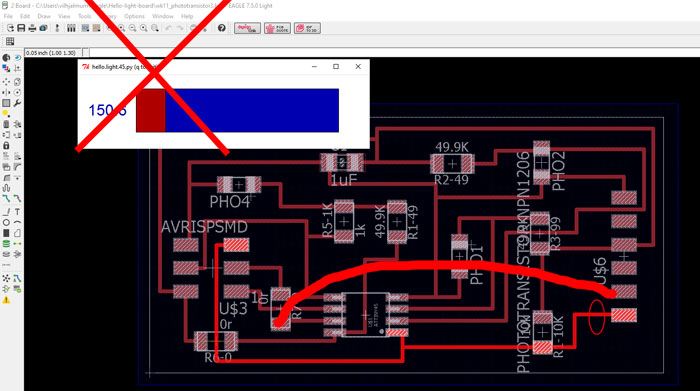
Unfortunately I made a mistake drawing the board. I could program the microcontroller but the computer could not read it back. I needed to disconnect one trace and make one new connection from one of the jumpers to RXD pin in the FTDI-SMD-Header.
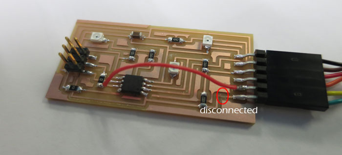
When I had fixed that problem everything worked and the Python program was reading the board. You can´t imagen how happy I was to see that red and blue graphic moving on the screen! YEEEES
Reading the photo transistor, Python program..
Related links
Connecting phototransistors or photodiodes in seriesUsing a Photoresistor
2013 Fab Academy Documentation - Input Device