Week #14: Input devices
Our tasks for the fourteenth week were:
- Measure something: add a sensor to a microcontroller board that you have designed and read it
Instead of using a premade sensor, I chose to build a sensor that would be fundamental to my final project, the Recoiler.
Since one of the purposes of the device is to measure the recoiled
wire length, an indirect way of measuring it would be by counting the
number of turns of the reel.
It's not a perfect measurement,
though. Since the wire has the liberty to move along the lenght of the
reel and due to the fact that the diameter of the already coiled
portion increases as the recoiling continues, this measurement
underestimates the actual length. But, this does not pose an issue for
my final project because it's actually good if I always recoil a little
more wire, just for safety (for example, if a group of students breaks
the wire insulation during a class experiment).
To count the reel turns, I could've used a limit switch, like the one shown below.
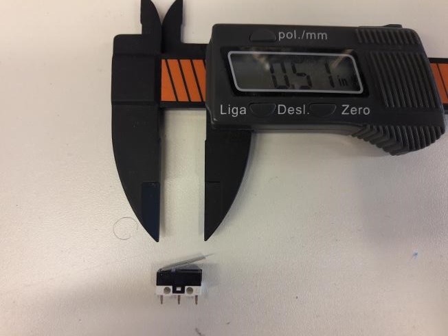
But,
I really embraced the DIY spirit on this one and chose to build a
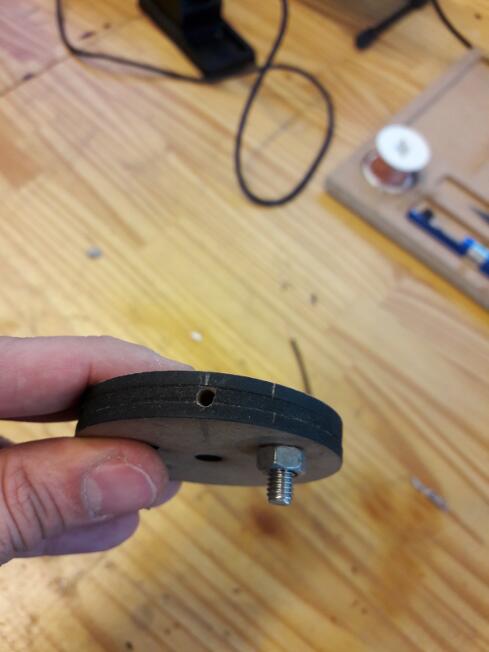
different sensor. It's quite simple: I inserted a piece of wire into
the component I built to adapt the DC motor axis to the reel (the
design and assembly is documented on Week 2 assignment).
The
idea I had in mind was doing something similar to slot cars: as the
copper strands slide along a pair o metal rails, the circuit is closed.
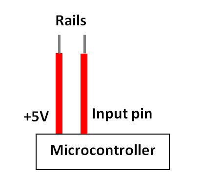
These are the metal rails:
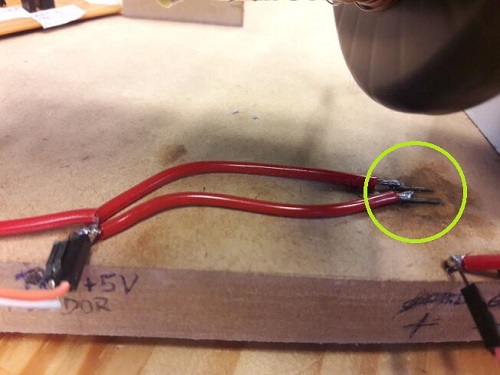
One
of these rails (staples, to be more precise) is connected to the
microcontroller +5V output and the other, to an input pin. Then, by
continuosly reading this input pin state, one can count the number of
turns.
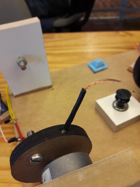
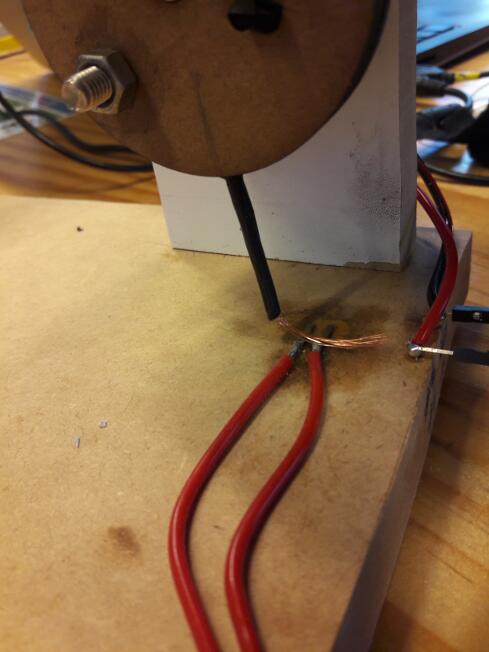
The first time I did this, I used an Arduino Uno, since
the microcontroller PCB I designed wasn't working. This is the setup I
tried at first:
For the initial tests, I used a code
that would turn on the built in LED everytime the circuit is closed
(when the copper strands touch both rails simultaneously, as shown by the following image) and off when
the circuit is open.
This is the code:
const int medidor = 5;
int estado_medidor = LOW;
void setup() {
pinMode(medidor,
INPUT);
pinMode(LED_BUILTIN, OUTPUT);
}
void loop() {
estado_medidor = digitalRead( medidor
);
if (estado_medidor == HIGH) {
digitalWrite(LED_BUILTIN,HIGH);
} else {
digitalWrite(LED_BUILTIN,LOW);
}
}
Then, I hit a bump on the road, a
problem that cost me at least 2 days to figure out how to solve. During
the tests, the assembly could always correctly detect a closed circuit:
as soon as I touched the copper strands on both rails, the built in LED
would light up. But, after removing the wire, the built in LED would
remain lit for a few seconds. Not only that, but it would also light up
randomly, even when the copper strands were not touching the
rails.
After
rebuilding the system several times, I couldn't, for the life of
me, solve this problem. Then, I stopped trying to just connect wires
and took some time studying the issue. The answer was here, but I'll write it here anyway.
Both AtMega and AtTiny microcontrollers have pins that, when configured as inputs with nothing connected to them,
will report random changes in the pin state, due to electrical noise of
the adjacencies or capacitive coupling with a nearby pin. So, that's
the reason why the assembly could correctly detect a high level but not
a low one, and this also explains why the built in LED remained lit
even after the circuit was opened: it was due to a capacitor being
charged and, during it's discharge, the microcontroller would wrongly
read the small residual voltage as a high level.
So, if I wanted
the microcontroller to correctly interpret a low level, I would need to
ensure that the pin voltage was a true zero, unlike electrical noise.
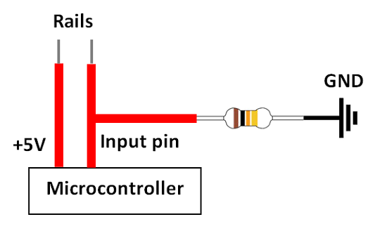
And this is exactly the job of a pull-down resistor:
by connecting the input pin to GND through a high-resistance resistor,
which allows very little current to flow, we make sure that the
electrostatic potential on both pins is the same (no current means no
potential difference!). Since one of them is GND (in this case, 0V),
the input pin is "forced" to achieve 0V potential.
And, as soon as I learned that, I also realized this was something I should have learned a long time ago: on Week 6 assignment,
most tutorials I read said something about pull-up and pull-down
resistors, but I guess I wasn't ready to learn that then. Well, better
late than never, right?
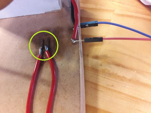
After this journey of discovery, this was my new assembly:
And
it worked perfectly! As soon as I touched the copper strands on the
rails, the built in LED would light up; at the moment I opened the
circuit, the LED would turn off. Perfect!
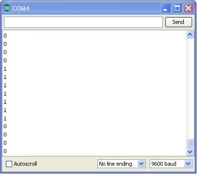
After I got my microcontroller PCB working (you can read about that odissey on Week 10 assignment),
I tested this setup again, but with my PCB instead of Arduino. But,
since my PCB did not have a built in LED, I used serial communication
to check if it was working. This is the new code:
const int medidor = 5;
int estado_medidor = LOW;
void setup() {
pinMode(medidor,
INPUT);
Serial.begin(9600);
}
void loop() {
estado_medidor = digitalRead( medidor
);
if (estado_medidor == HIGH) {
Serial.println(1);
} else {
Serial.println(0);
}
delay(50);
}
And
it worked just fine! As long as I kept the copper strands touching the
rails, the serial monitor would show a sequence of 1's; as soon as I
opened the circuit, it would show a sequence of 0's.
And that's what I got for Week 14 assignment! This contraption was effectively used on my final project.