Week #10: Output devices
Our
tasks for the tenth week were:
- Add an output device to a microcontroller board I designed
and program it to do something
I
chose to do this week assignment in a way that I could kill two birds
with one stone: by choosing to drive a stepper motor, I learned
valuable information that would help me both with my final project and Week
#9 assignment, since we chose to build a Draw Bot.
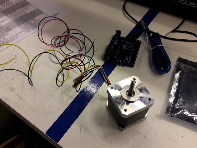
As it was kind of urgent to learn how to drive a stepper motor for our
group project, I chose to use an Arduino Uno and, after that, I
designed my own microcontroller board. So, my first step was to learn
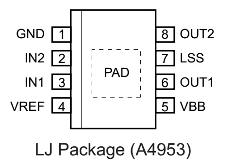
how to use a driver IC - in this case, the A4953, which is a 8 pin SMD
IC (datasheet here).
This particular driver is a full H bridge, which is quite
simple: 2 pins are used for the logical input (IN1 and IN2), which is
provided by the
Arduino Uno (later, provided by the microcontroller board I designed),
2 pins are the power outputs (OUT1 and OUT2), 1 pin is the ground
(GND), 1 pin is the
reference voltage for logical operations (VREF, +5 V), 1 pin is the
power
supply (VBB, +12 V), 1 pin is to set the maximum output current (LSS,
up to a
maximum of 2A).
This is the IC pin-out diagram:
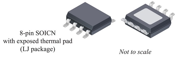
This IC has quite an interesting feature: there's an exposed pad that
serves both as GND and as a thermal dissipator. The datasheet suggests
a very complex assembly to achieve the best thermal dissipation:
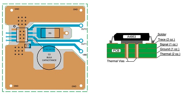
Since I did not intend to use the maximum current output (our stepper
motors can handle up to 0.6 A), I figured thermal dissipation shouldn't
be a major issue and designed a much simpler board. In fact, since I
could not find a reasonable explanation on why to use two capacitors
(the datasheet suggests two in paralallel: a 1 uF as close as
physically possible to the IC and a larger one, called bulk capacitor,
with 100 uF capacitance), I used only one, with 10 uF capacitance (I
did not have larger ones available at the time).
The RS resistor defines the maximum current output. Since I was going
to use a power supply that could limit the current output on the
desired 0.6 A, I simply short-circuited the pins LSS and GND, which
means that the IC maximum current output would be, at most, 2 A. This
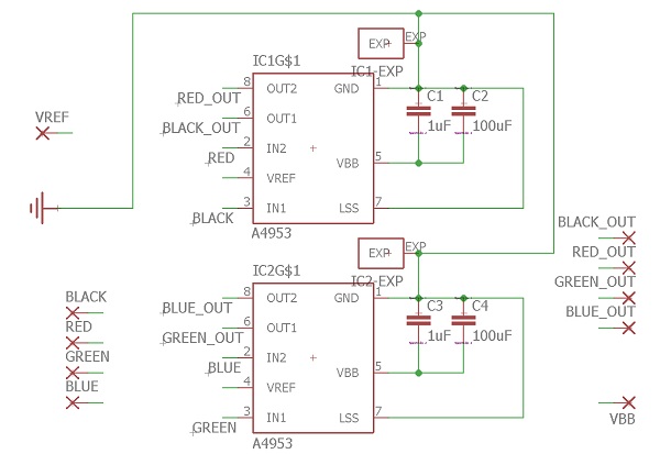
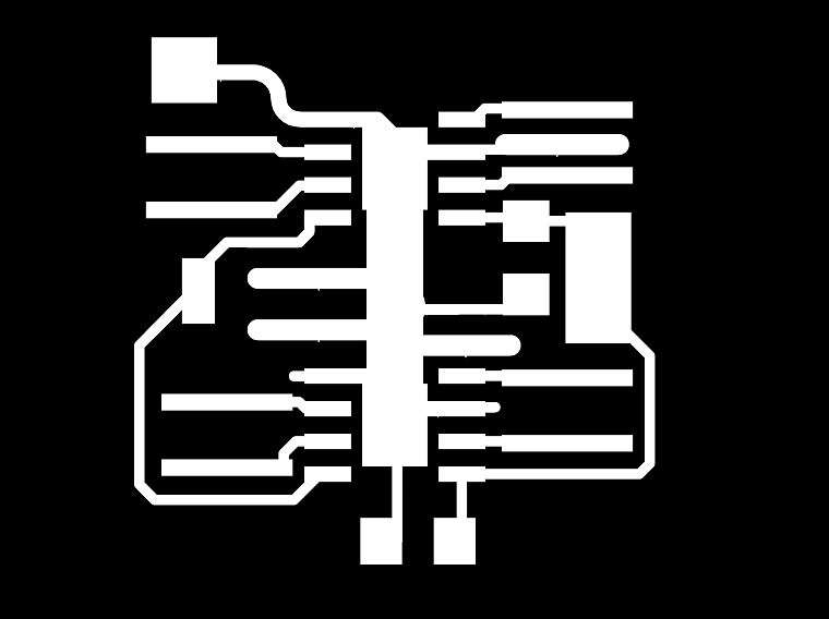
is the board I designed (link here, password abc123. As
I could not find the A4953 IC in any of Eagle's libraries, I used the
L5973D, which has the exact same dimensions, including the exposed pad):
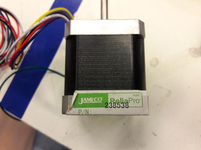
The colors (Black, Red, Green and Blue) refer to the stepper wires,
which I will explain now. The stepper motor I had available uses 4
coils and 6 wires: each pair of coils has a common ground (yellow and
white wires) and two poles (red and black for one coil and blue and
green for the other) and needs one A4953 IC.
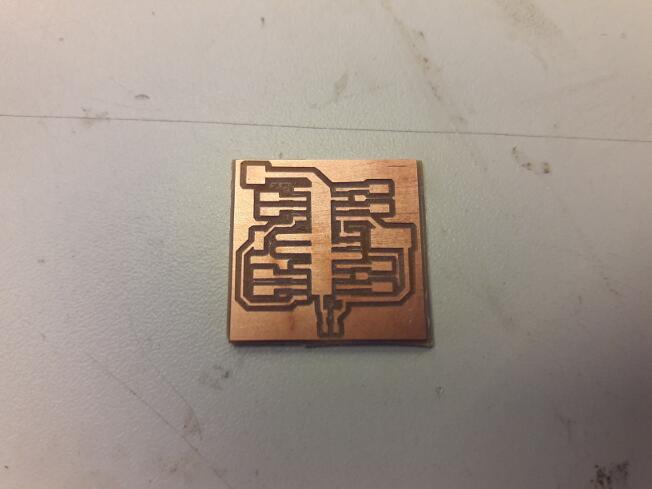
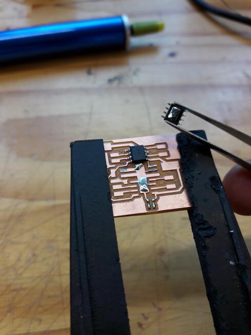
To assemble the board, I started with the ICs by placing a drop of
solder on which I placed the IC exposed pad:
After that, while assembling the other components, I noticed three
things:
1) I forgot to place pinheads for the wires, so I had to solder them
directly to the PCB;
2) I chose the wrong package for the capacitor, so there was room for
only one, placed diagonally;
3)
I did not have 100 uF capacitors available. So, instead of one 1 uF and
one 100 uF capacitor, I put a single 10 uF capacitor (and it worked).
After the driver PCB was assembled, I wrote a simple routine on Arduino
IDE to make the motor run one step every 0.2 s:
void setup()
{
pinMode(8,OUTPUT);
pinMode(9,OUTPUT);
pinMode(10,OUTPUT);
pinMode(11,OUTPUT);
#define
RED 8
#define BLACK
9
#define BLUE
10
#define GREEN
11
}
void
loop()
{
digitalWrite(RED,HIGH);
delay(100);
digitalWrite(RED,LOW);
delay(100);
digitalWrite(BLACK,HIGH);
delay(100);
digitalWrite(BLACK,LOW);
delay(100);
digitalWrite(BLUE,HIGH);
delay(100);
digitalWrite(BLUE,LOW);
delay(100);
digitalWrite(GREEN,HIGH);
delay(100);
digitalWrite(GREEN,LOW);
delay(100);
}
This is the
result:
I know this is not the only (and arguably not the best) way to drive a
stepper: for more torque, I should activate two coils at a time. But,
the goal was to see if the driver PCB I designed worked, and it did.
To fix the problems I noticed during the first assembly, I made some
changes to my PCB design (link here, password abc123):
The
next step was to design my own microcontroller PCB, instead of using an
Arduino kit. Since designing this PCB is required for the completion of
may assignments, including the Final Project, I decided to give it a
separate page.