Week #2: Computer-aided design
The tasks for the second week were:
- Learn about different design tools
- Design a possible final project and post it on my website
I
had previous contact with the following softwares: Inskscape,
GIMP, SketchUp, CATIA and AutoCAD (a very brief contact with
the
last 2). But, I had never developed any 3D model for a printer and I
was told that SketchUp could be a not so great choice.
Since I
teach math and I am particularly biased towards parametric design, I
was told to try out Creo. And, as I would do if I was studying math, I
tried to learn something about 2D design before trying out 3D design;
so, I proceeded to download Creo Sketch.
Just to get the hang of
it, I tried to design a simple gear: 10 cm diameter, 20 teeth. It took
me about 20 minutes to draw my first conclusion: Creo Sketch is not
made for that! As the name says, it's for quick drawings, not for
precision. It's a really nice (and free!) substitute to Paint Brush,
since it allows for layers, but not what I needed.
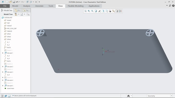
Next try: Creo Parametric (30-day trial). Lengthy installation, seems
like a bulky program. After that, a warm welcome:
Well, ok... gotta make the most ot of those 30 days, right? As soon as
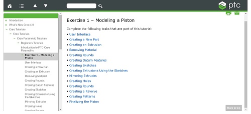
I downloaded the program, I got an e-mail with links
to a tutorial, so I thought this would be a good point to start.
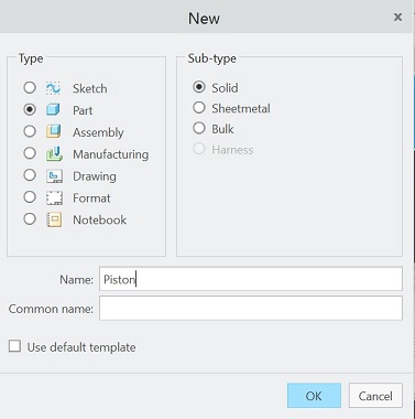
The tutorial is based on modeling a piston. The first step was to
create a new part:
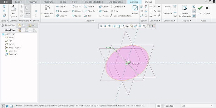
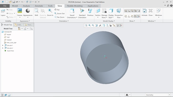
Now,
I will extrude something, which I believe (at this moment) is going to
be the piston head. For that, I use the center and point tool, and I
notice a major difference from what I knew about AutoCAD: you can't
type the diameter as you draw; you have to draw a circle with arbitrary
diameter and the double-click this dimension to reset it to the desired
value. Not too practical, but that's ok.
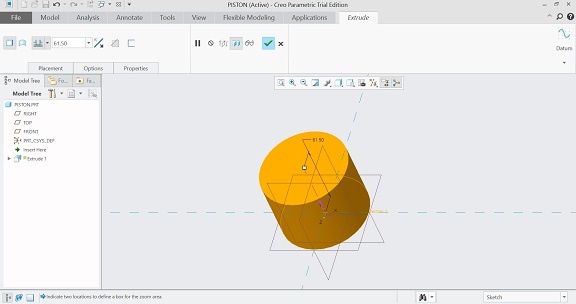
After you click "Ok", the circle is automatically extruded and you can
manually set the extrusion depth.
Then, after you click "Ok" again, you can manipulate the object.
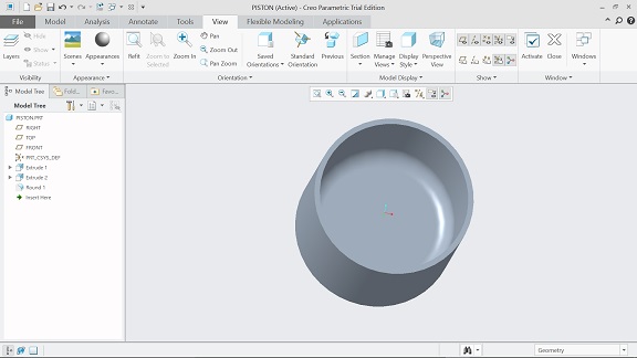
Ok,
now we're going to remove some material so that the connecting rod can
fit inside. It's pretty much the same process: extrude, circle. I took
me a while to figure out how to rotate the view dynamically,
but
eventually I got this:
Now, I have to round some edges. It's pretty straightforward: I just
have to click "Round" under the "Engineering" group.
The
next step was to create some datum features: a plane and an axis. I
must confess I did not get the point of doing this, but I think it will
be useful in a future step.
After
that, I felt the instructions got a little confusing, specially since I
don't have a third mouse button on my laptop (and no, clicking both the
left and right buttons at the same time does not work). So, I got a
little frustrated and decided to design something by my own: my final
project conveyor belt. After some struggle, I got something like this:
I drew both the belt and the wheels as a single part. That's why they
look made from the same material.
Funny
story: on the next day, talking to a colleague, he told me that you
just CAN'T use Creo without a mouse. At first I was skeptical, but he
convinced me really quick. So, I got a mouse and started all over; this
time, however, I created each part separately.
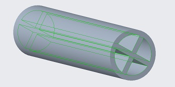
The first parts I
designed were the wheels of the conveyor belts, each one being
cylindrical with a length of 20 cm and a diameter of 5 cm. Here's what
I got:
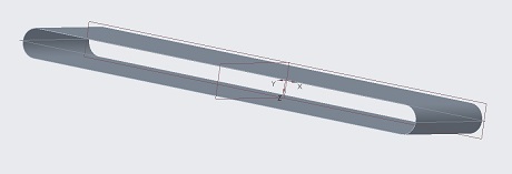
Then, I designed the belt itself, a sheet having a width of 1 mm:
As
the initial mixture rolls over the first conveyor belt, at some point
the ferrous pieces will be attracted to an eletromagnet and the rest
will follow it's way to the end of the belt. I want what is left of the
initial
mixture to roll over the entire length of the second conveyor belt; so,
both conveyor belts will need to be placed close to the sides of the
box.
Thus, the
magnet has to move along a rail in order to drop the ferrous pieces in
an adequate container. It's kinda hard to understand the desing with
words only, so it'll all be clear when I show you the complete assembly.
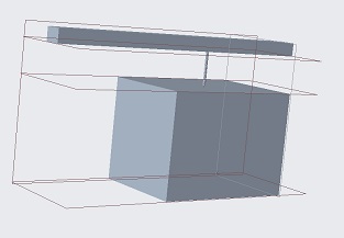
Since
I still haven't calculated the necessary currents, it's hard to
estimate the electromagnet size. Being really conservative, it's safe
to say it'll fit inside a 20 cm x 15 cm x 15 cm box. This is what I got
for the magnet and it's rail:
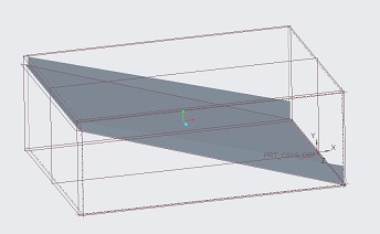
After the ferrous pieces are picked up, they are dropped on a ramp (the
box shown in the figure is 40 cm x 55 cm x 20 cm) :
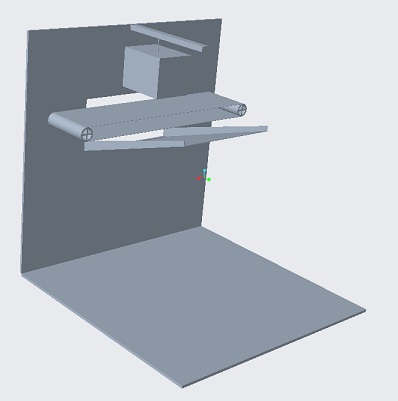
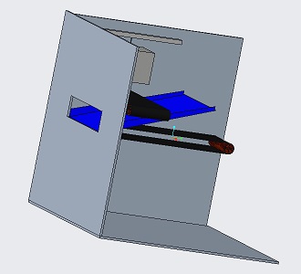
Now, I'm going to try to assemble together all the pieces I designed.
This is what I got:
As
you can see, this is far from a final design: the conveyor belt is
"floating" inside the box, and also it is not powered by a motor.
But, it's possible to get a flavor of what it will become :)
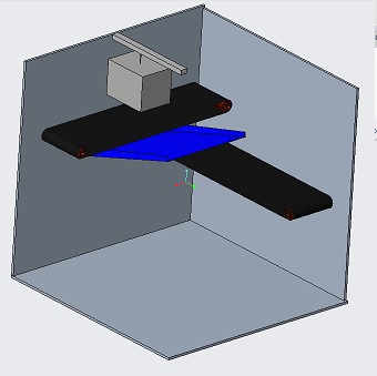
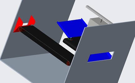
After
that, I added the second conveyor belt (the one where non-ferrous
metals will be separated from non-metallic materials) and put on some
colors to make it easier to tell parts from each other:
The
final part is another ramp, one that also serves as separator for
non-ferrous metals and non-metallic materials. The result was:
If you want to check out the 3D model files (parts and assembly), click
here
(the password is abc123).
*
UPDATE *
It
was only later during the
course that I noticed this week assignment
was also about 2D modelling. By the time this happened, I had already
changed (and, as a matter of fact, built) a different final project:
the Recoiler.
So, I am
going to describe the 2D modelling I did for my final project in order
to adapt the DC motor axis to the reel, using the laser cutter. For
that, I used Fusion 360.
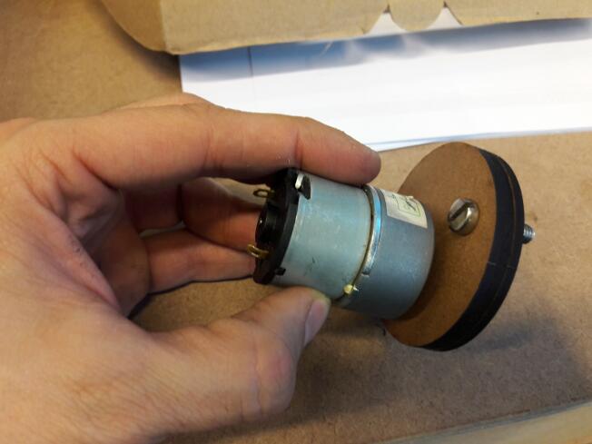
To understand the problem, look at the following figures:
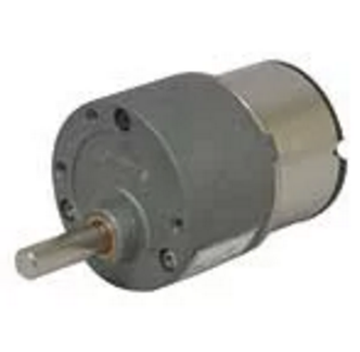
,0
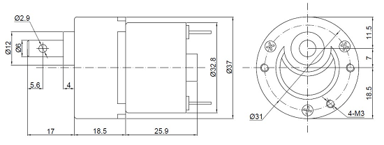
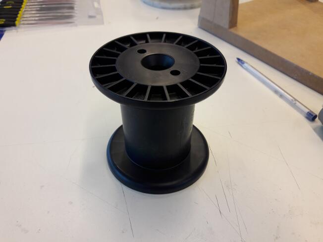
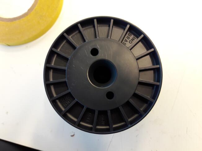
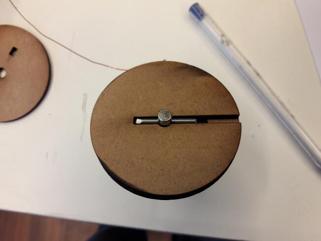
As
you can see, the motor axis has a hole. In order do adapt the axis to
the reel, which you can see below, I designed a piece made of three
layers of 3 mm MDF.
I am going to explain this piece as I show the design. As I said
earlier, I used Fusion 360.
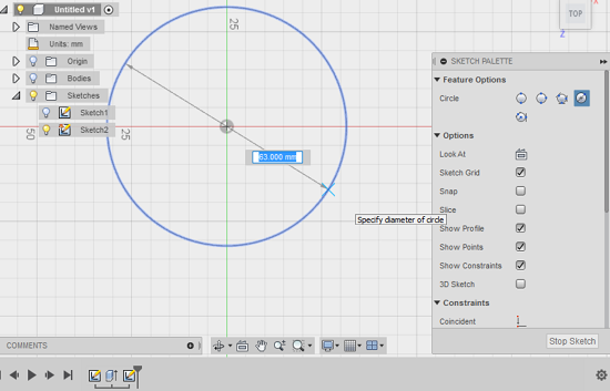
The
commands are quite practical: for example, in sketch mode, you press C
if you want do draw a circle, then you choose its center and type it's
diameter. Simple as that.
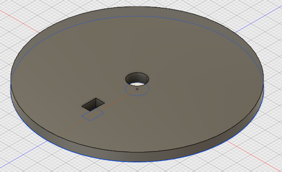
All the 3 layers that make up the
piece are circular and the DC motor axis goes through their centers.
The first and third layers are simply a circle with one circular hole
for the motor axis and a recatangular hole for a pin that will hold the
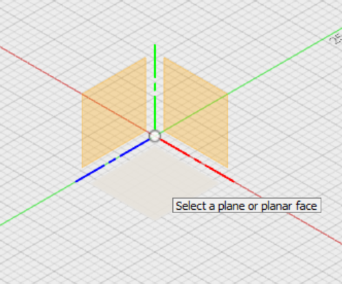
layers together. To draw them, I started by choosing a plane to sketch
and drawing a circle:
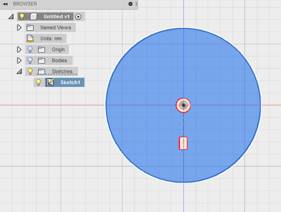
Then, I drew a circle for the motor axis and a rectangle for the pin:
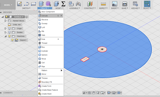
In
order to make a 2D PDF for the laser cutter, we first need to make a 3D
piece. In this case, I just had to extrude the above drawing for 1.3
mm, the thickness of the MDF board.
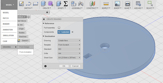
Then, to generate the 2D design, we click on Model -> Drawing
-> From design:
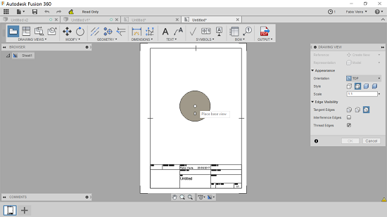
After that, Fusion opens a new window in which you can choose the
object view and place it on the drawing:
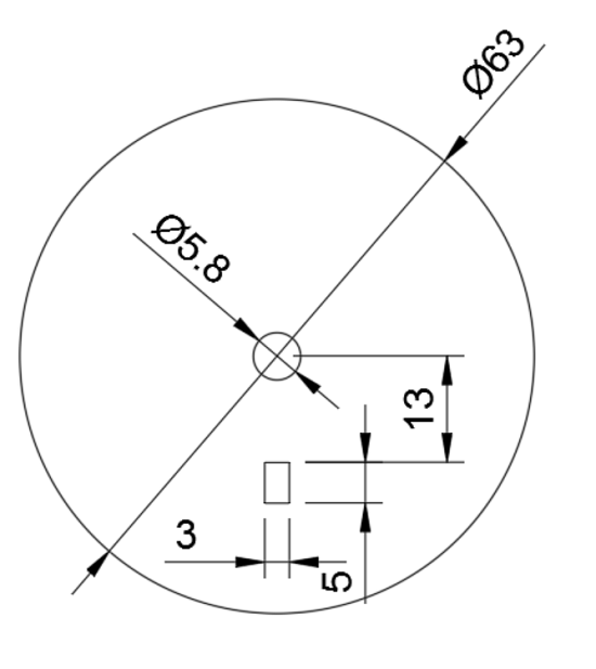
We can also add some dimensions:
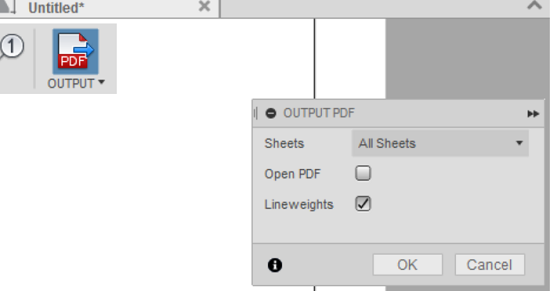
Then, we simply click on "Output PDF":
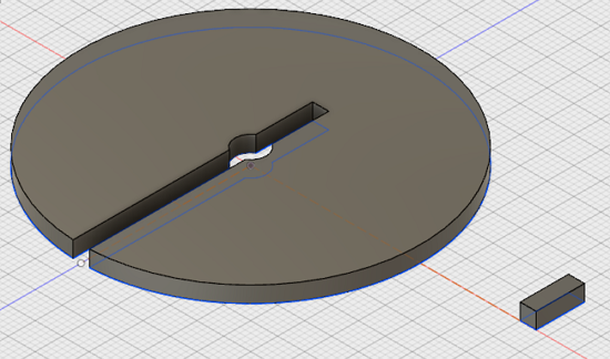
The middle layer has a cut in which a metal rod (a cut rivet) will be
inserted:
On the right side, you can also see the pin. This is the 3D model:
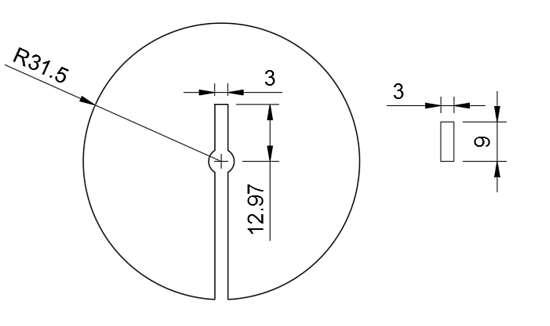
And this is the 2D drawing with the dimensions:
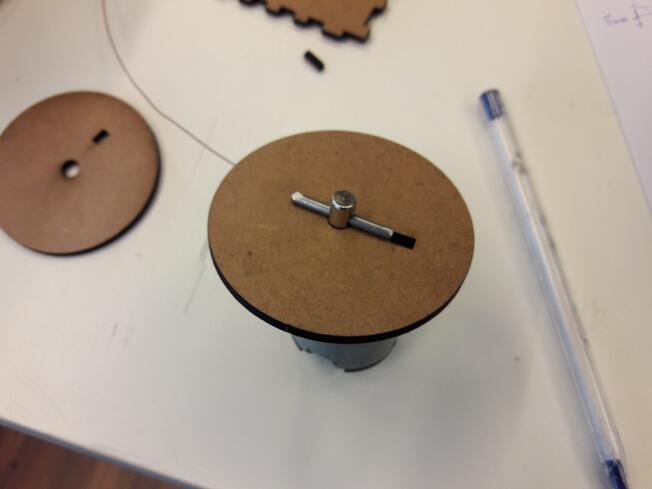
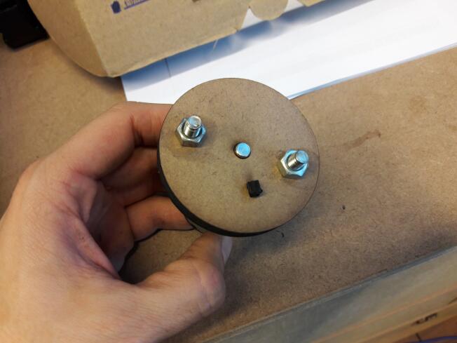
This is the assembly process after laser cutting the layers:
If you want to check out the 3D and 2D model
files, click here
(the password is abc123).
And that's my progress for the second week. I sure learned a lot, and I
also found out that 3D design is almost therapeutic.