Assignment:
A_ automate your machine
B_document the group project and your individual contribution.
B_document the group project and your individual contribution.
A_ Automate our 1st solar tracker prototype
I have collaborated with the project providing most of the design of the structure and developped along with Dom, Trinidad and Jc (members of my group) the electronic and sensor input/2/motor strategy.
Link to video presentation.
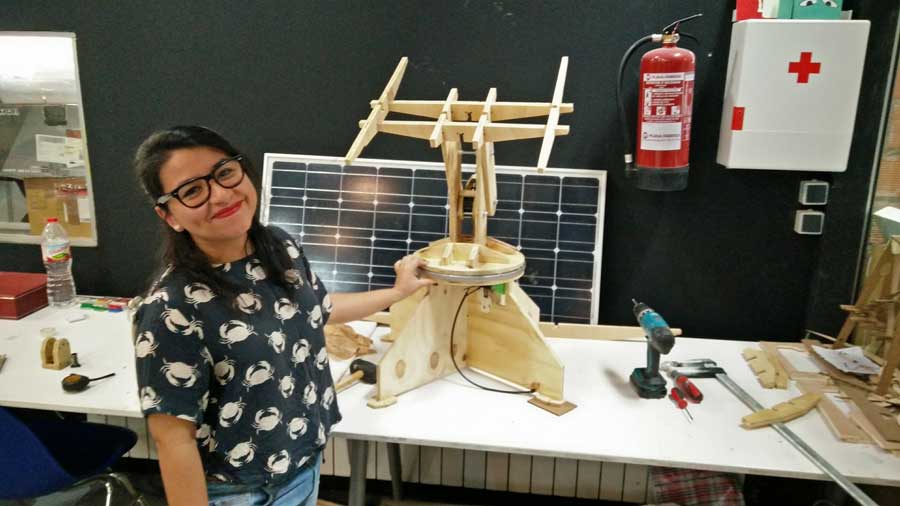
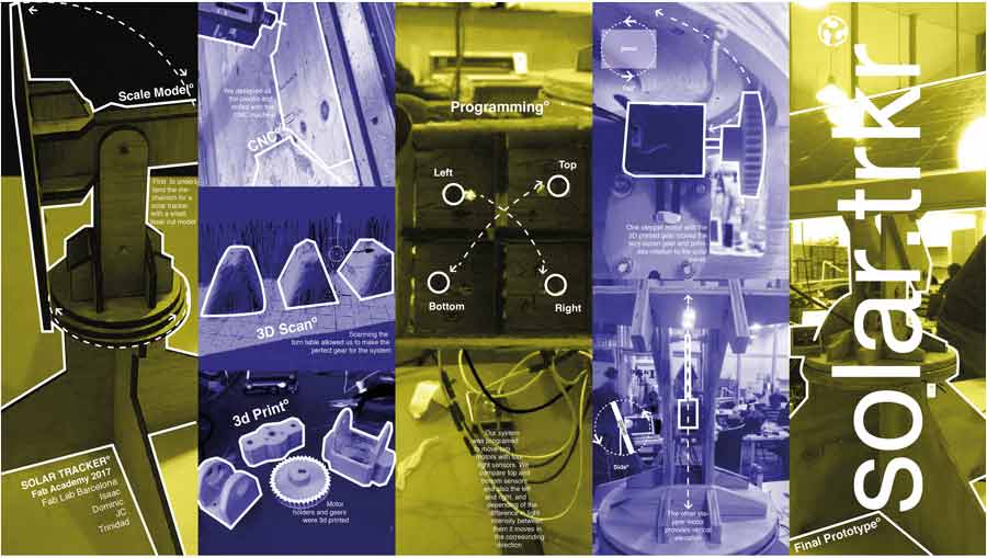
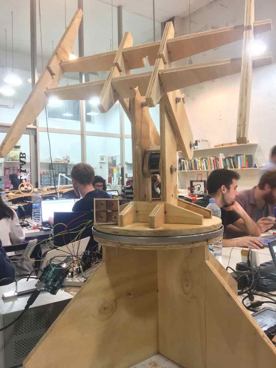
I started this assignment making adjustments to the rhino file of the model we had laser cut (during the mechanical design week) and convert it to a 1:1 scale.
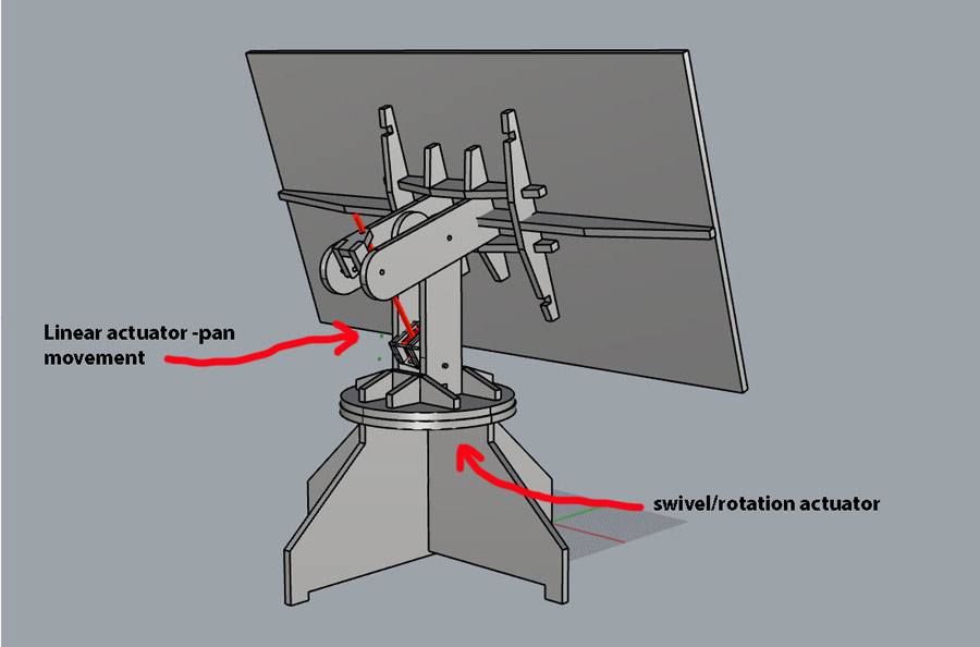
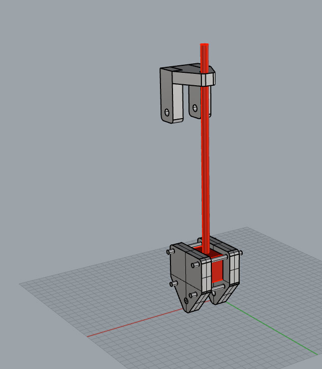
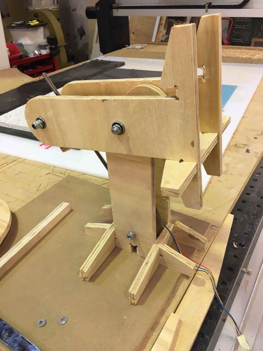
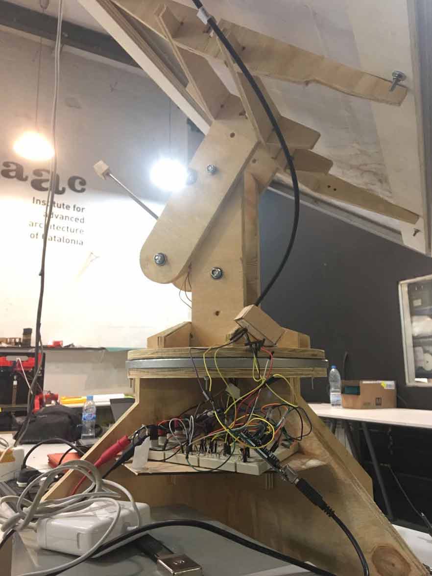
I also did some design adjustements and improvised actuator mounts. The group had agreed to produce 3D printed mounts but they were not resolved at the time of milling and we needed a quick solution to get a working prototype of the machine so I invented a system that could be milled in the batch. This way we can test the design functionality, integrate the electronics and the programming.
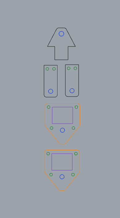
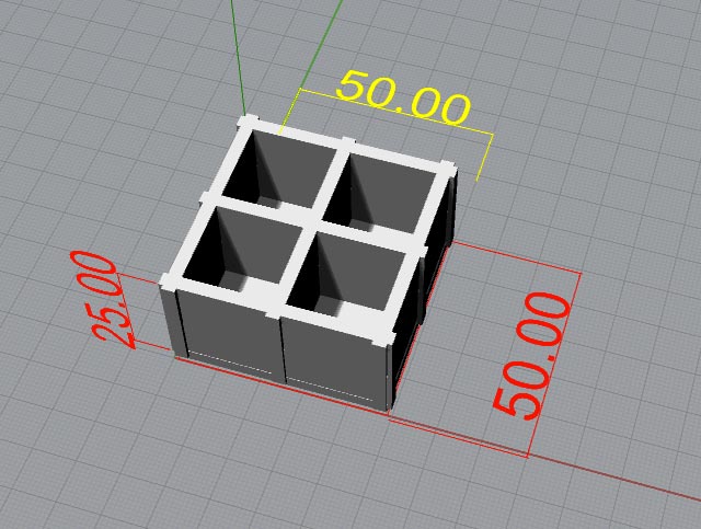
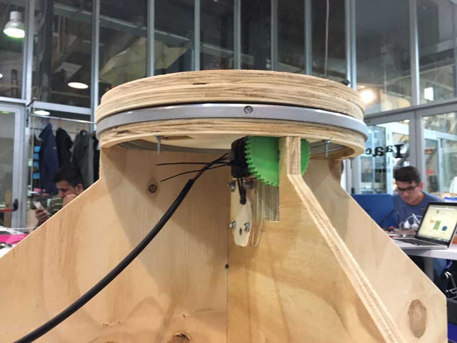
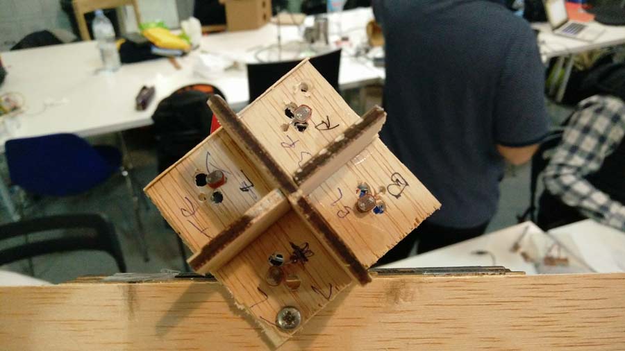
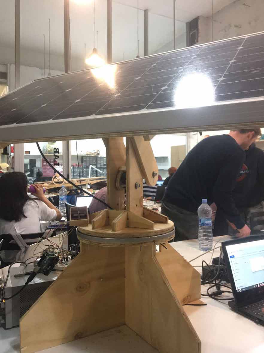
I also designed the light sensor box. It is square and divided in 4 compartments -one per sensor. It will be attached to the panel at one extremity of the panel so it moves along with it.
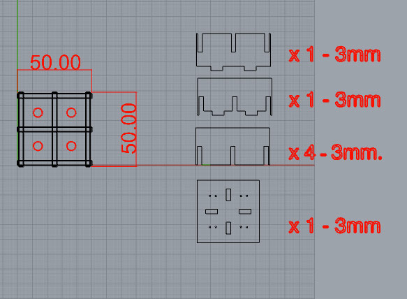
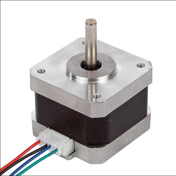
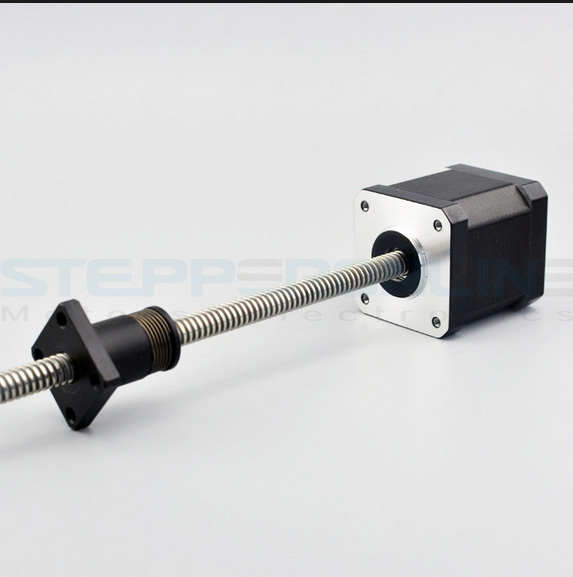
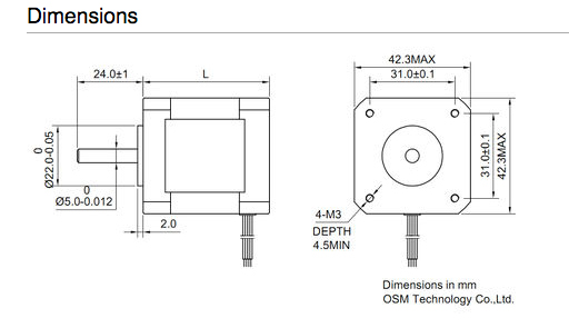
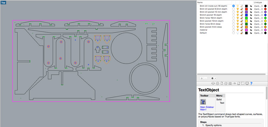
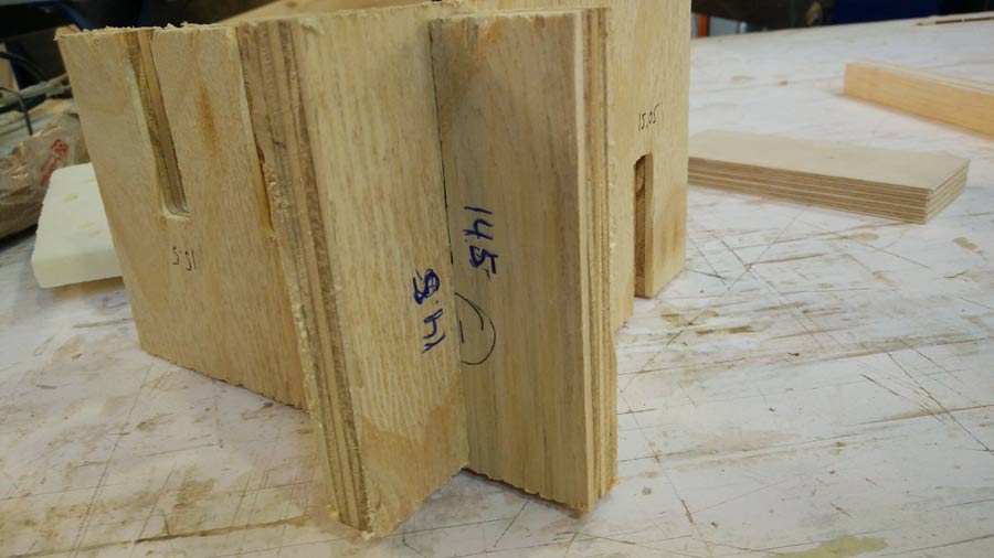
I prepared the rhinocam file in a 1:1 scale that can integrate the Nema actuators. I scaled 2D (in rhino) all the objects to be milled so slotting would be at 14.5 mm and made the cam file of the different toolpath.
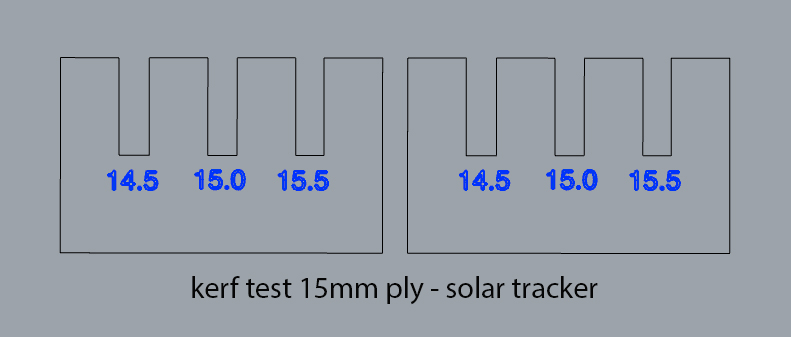
We are using 15mm. low grade plywood. I made a kerf test at 14.5, 15.0 and 15.5 mm. The 14.5 was the best so the slotting are tight and sturdy.
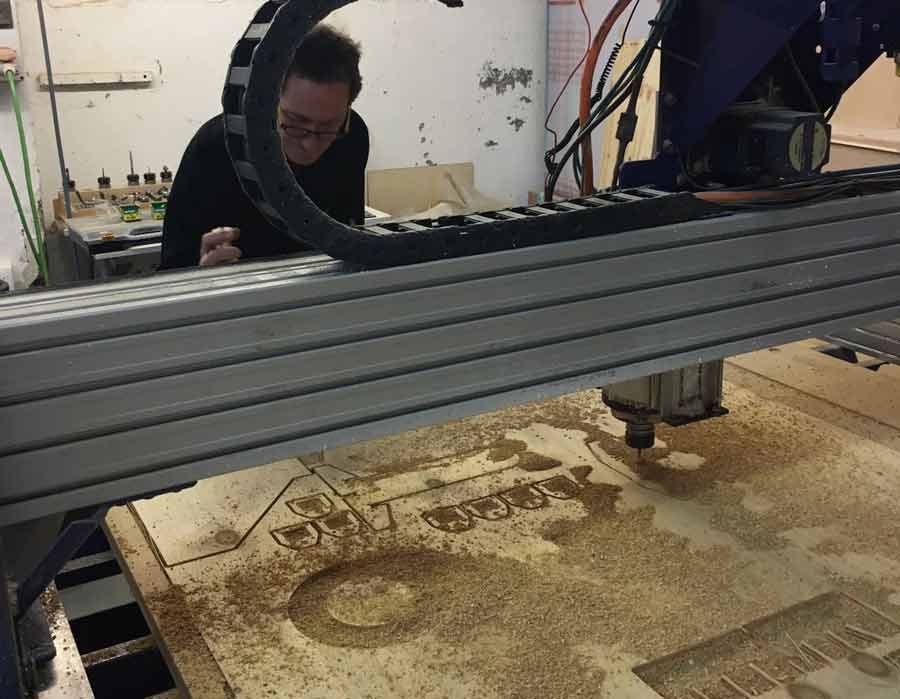
I milled it on a shopbot with a pretty old sacrificial board. Because I had put only 1mm. extra of depth cut in many areas the bit did not mill completely through the material. No big deal. A bit of sanding and that was it. Many of the measurements were not precise enough though and we had to adapt some parts manually. I took notes of the flaws to correct the files for the next iteration.
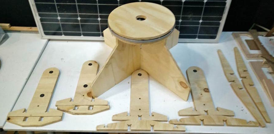
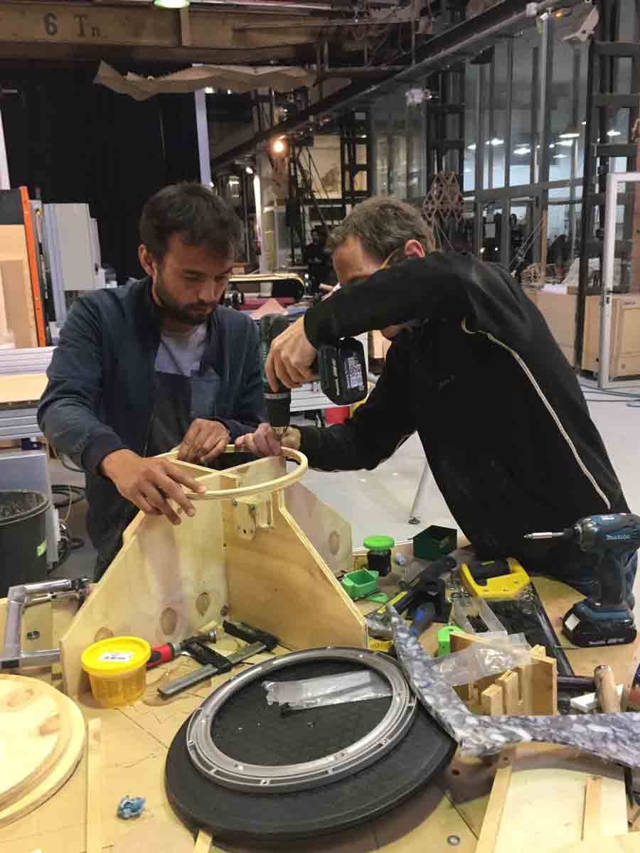
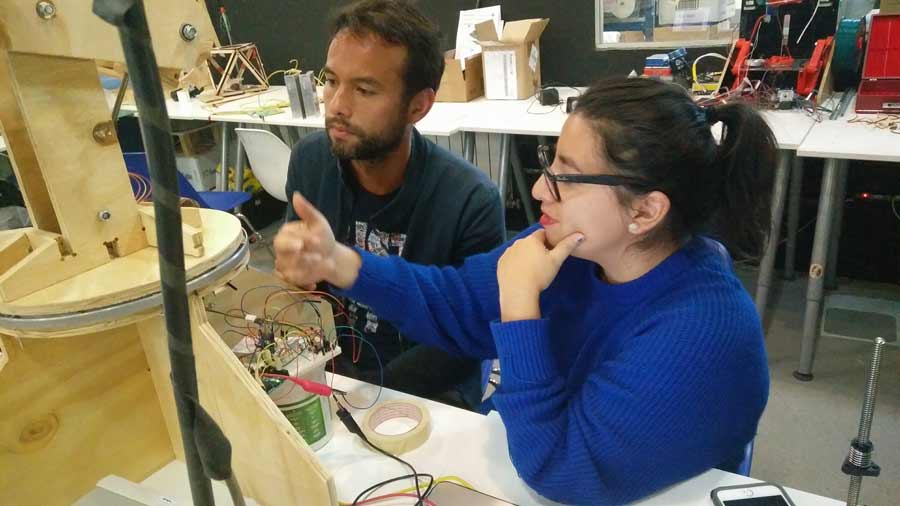
We went on assembling the different parts and putting the machine together.
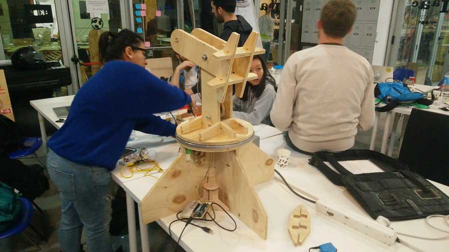
In paralel to adjusting the design and fabbrication other members of th group implemented the electronic solutions and did the programming.
We had discussed 2 options:
arduino + shield + stepper motor driver
arduino + gestalt + Fabnet USB (running on C or python).
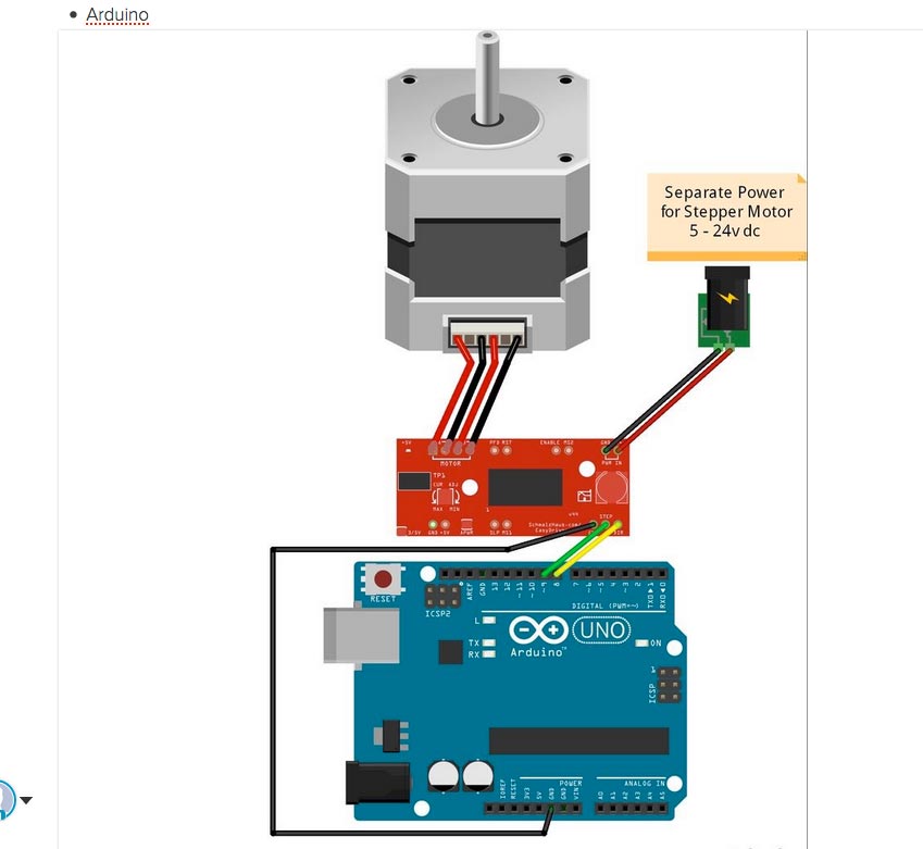
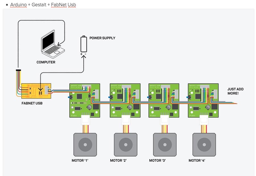
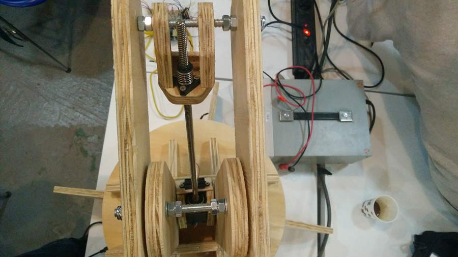
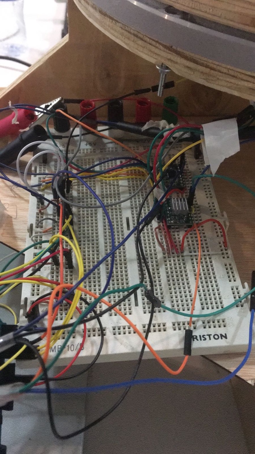
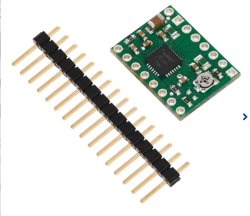
At the end we decided to go for the 1º option as it was the most simple solution and none of us has much expereince with programming. We worked with an Arduino and a breadboard which hosts 2 polulu steppermotor driver.
The code is based on an Arduino sketch from an instructable.. Trinidad and JC rewrote it for the sensors to seek maximum light possible. Each sensors is placed in a compartment of the little wooden box attached to the panel. When a sensor receives minus light it sends a signal for the actuator to correct the orientation of the panel so the sensor receives maximum light. Two of the sensors actuate on the pan axis and the 2 others on the rotation axis. The combination of the 2 maintains the panel oriented towards the sun.
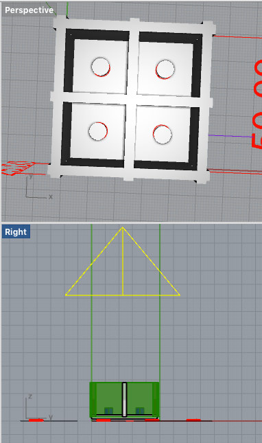
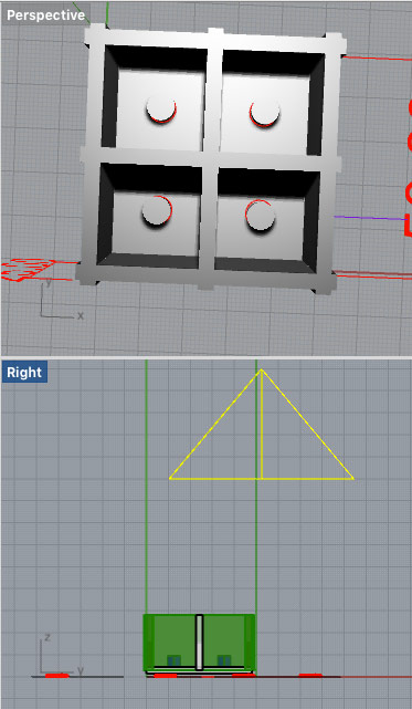
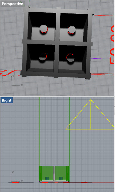
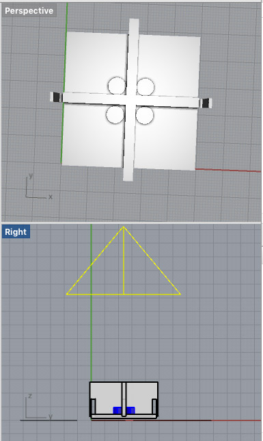
Here the 1st simulation of how the light in movement interacts with the sensors.
After making light tracking test we realized that there was not enough light difference between each sensors to have the motor react in reorienting the panel in the direction of the light. So we took out the external wall of the box. That solved the problem and we had direct response from each sensors. I made a few simulation in which I also located the sensors closer to the center and the walls seperating each sensors. This way maximizing the light difference between each sensors.
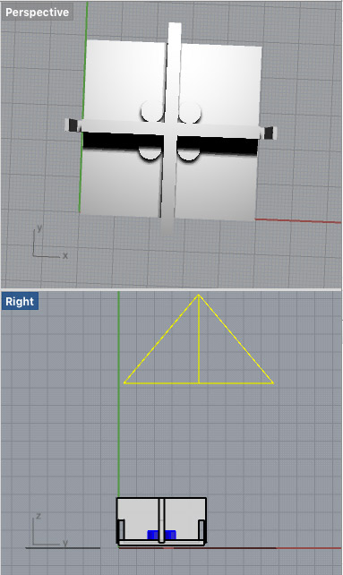
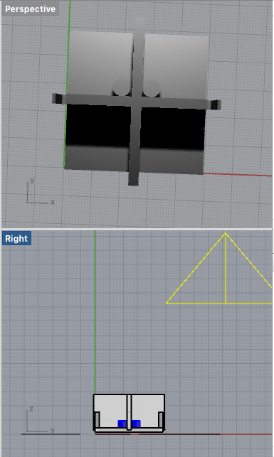
A 2º simulation of how light source in movement interacts with the sensors.
This model of the solar tracker will serve essentially to proove the different aspect of the concept.
Here the links to the videos of the different phases of fabrication and automation of the . solar tracker or Google drive video folder
Here the link to the group website.