Assignment:
A_ add an output device to a microcontroller board you've designed and program it to do something.
Design the board
I will make a stepper motor controler board with a led and a light sensor.
The led could be used to indicate that the signal gets to the steppermotor. The stepper motor I intend to use are bipolar so I use the sample board from the fab academy class archive.
I am adapting the board to insert a light sensor and a led. I researched in the Fab Academy archive to find example of students who have done this board and found this assignment that helped me with identifying the components.
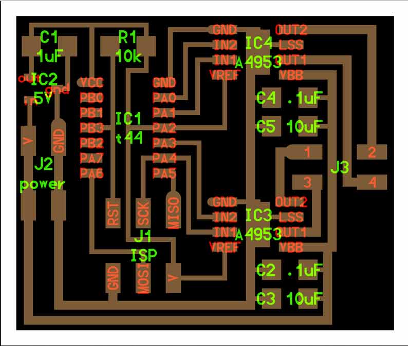
The bipolar stepper motor circuit board uses 4 integrated circuits:
IC1: (1) Microcontroller Attiny44
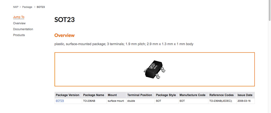
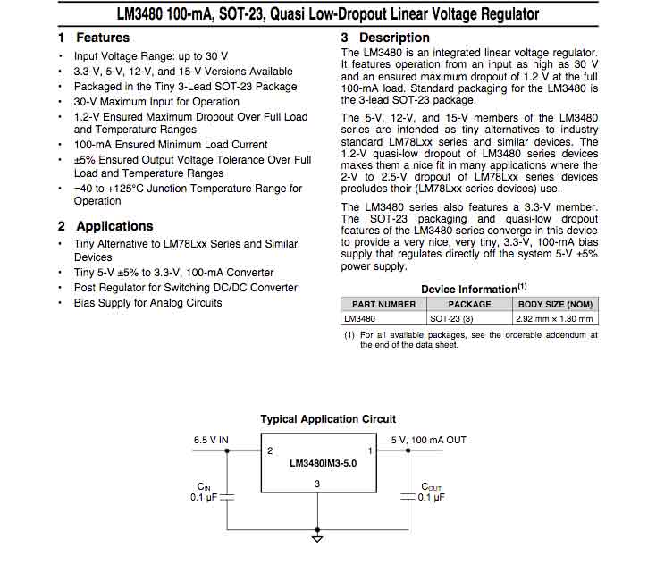
IC2: (1) Power (voltage) regulator (sot23), limiting 5v for Attiny 44.
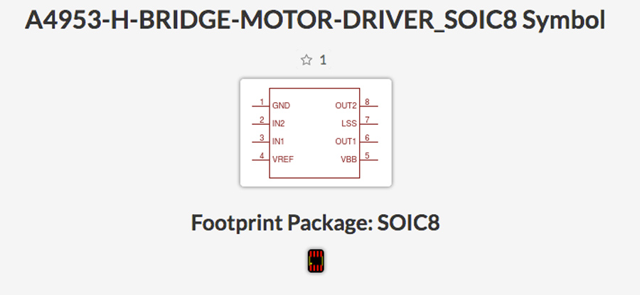
IC3: (2)IC4: H-bridge A4953) (to power the stepper motor).
The other components required are:
2 x 4pin header for power supply (5V)
1 x 6 pin header for data
3 x 1uF capacitator
2 x 10uF capacitator
1 x 10K resisitor
To this I will add:
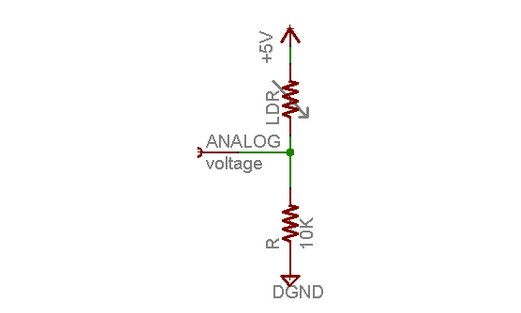
1 x light sensor (LRD)
1 x 10k resistor
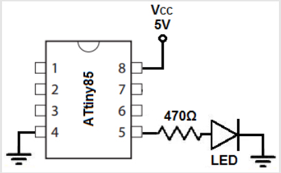
1 x led
1 x 499k resistor
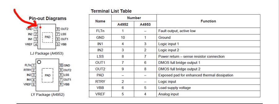
I am not shure about what are the difference between Vbb and Vcc. Looking at the board Vbb appears to be the trace that corresponds to the Voltage from power source to output of the H-bridge, the traces are wider on Neil's board probably because it is designed to carry higher voltage. Nevertheless on my board I made them the same size as the others.
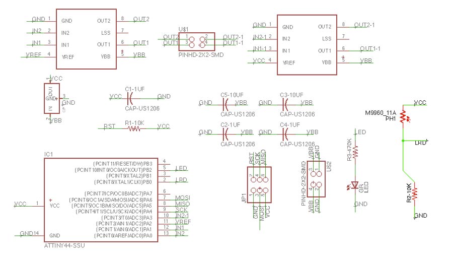
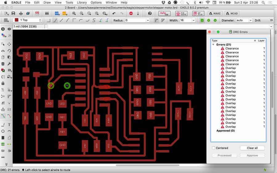
I created the schematic inserting the components I am adding and traced the routes. I did different versions of the routes and finally got a final one and went on milling. It took me a while to warm up on Eagle but I quickly picked it up again. Now I feel more comfortable to work with it but had some issues with overlapping error message when doing the traces. In some cases I could not match the pins and that made conflicts. . Example Vref to V, PIN02 to Vref...........
Finding the components in the library is another issue and understanding why this one more than another is still quite a dilemma but I did refer to datasheet and search the web for references.
The first milling intent did not worked well. For some reason when I did the outline the fab module did 2 traces following both sides of the outline trace. And that scrapped my board.
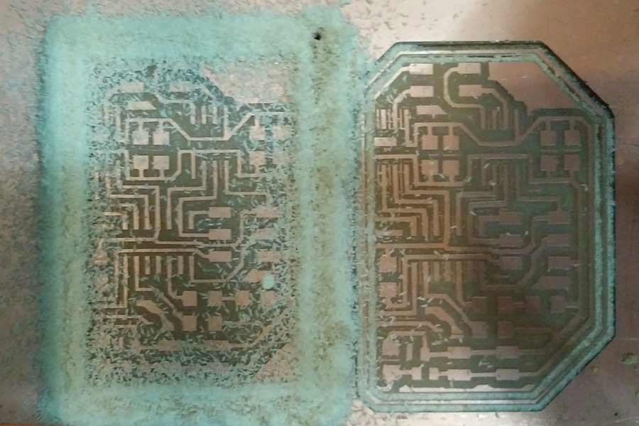
Before sending the file again I realized there were trace mistakes on my board design. I had omitted to connect the LSS pin of the H-bridges to the GND. I did the correction and reexported both trace and outline. The outline came out again as 2 lines in Fab Module so I eliminated the black part outside the outline on photoshop and that solved the problem. That helped me understand how does the Fab module actualy works: it mills a line at the exact spot where the white and the black meet on the board. Since I had framed the white frame with black it did milled a line on each side of the frame. That is important to understand when making the outline.
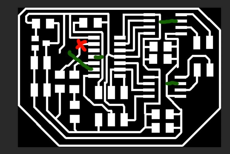
Discussing with a fellow students I realized that I had connected the sensor to a PB pin ( a digital pin) of the Attiny and this way it cannot work to read the light variation. Because peripherals with relative readings must be connected to an analog pin. The sensor will read the light but will have no range. It will either be on or off. Anyhow I decided to make a bridge with the sensor to pin P07 on the board instead of redesigning it in Eagle and remill a new board.
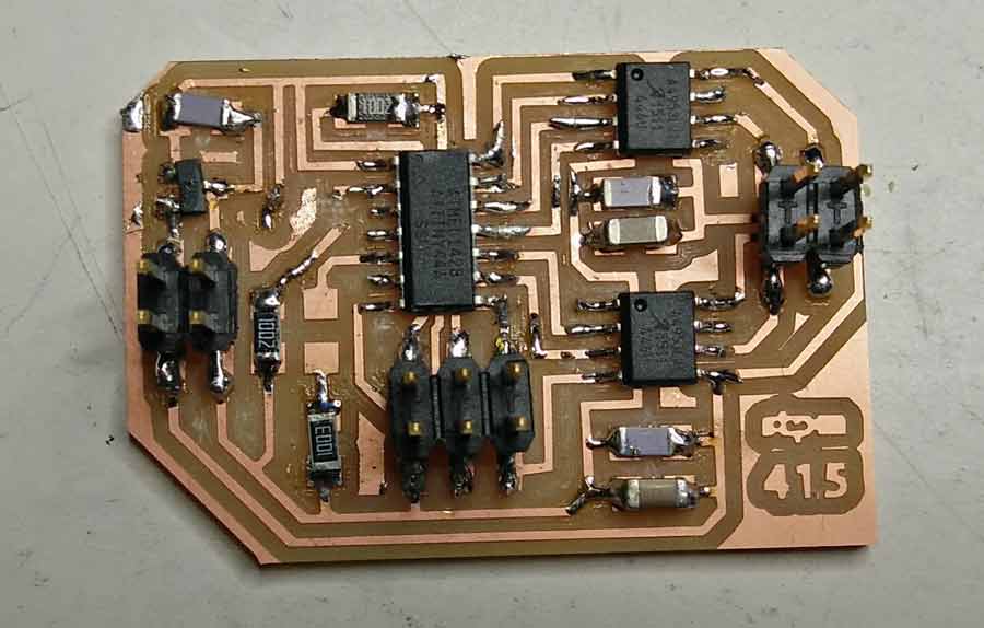
In the picture below:
in green are the tracing mistakes which were corrected.
In red the bridge I will do with a wire to connect the light sensor to PIN07.
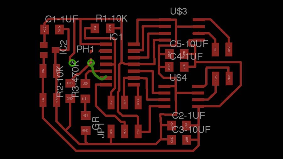
Here the final trace of the board with traces corrected (+bridge in green).
Stuffing the board
Stuffing the board went as usual. I do this kind of work in the morning when my mind is fresh and there is not too much activity in the lab.
Testing the board
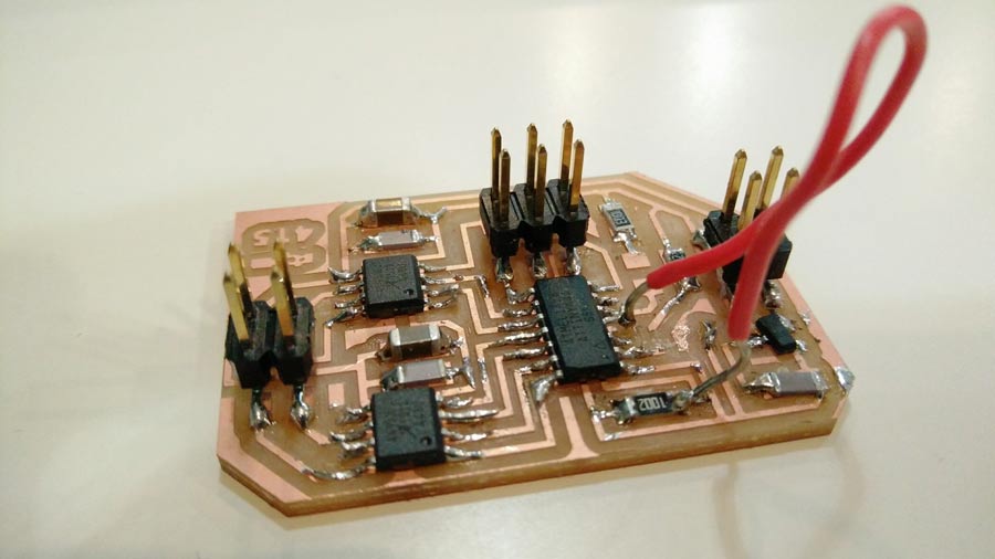
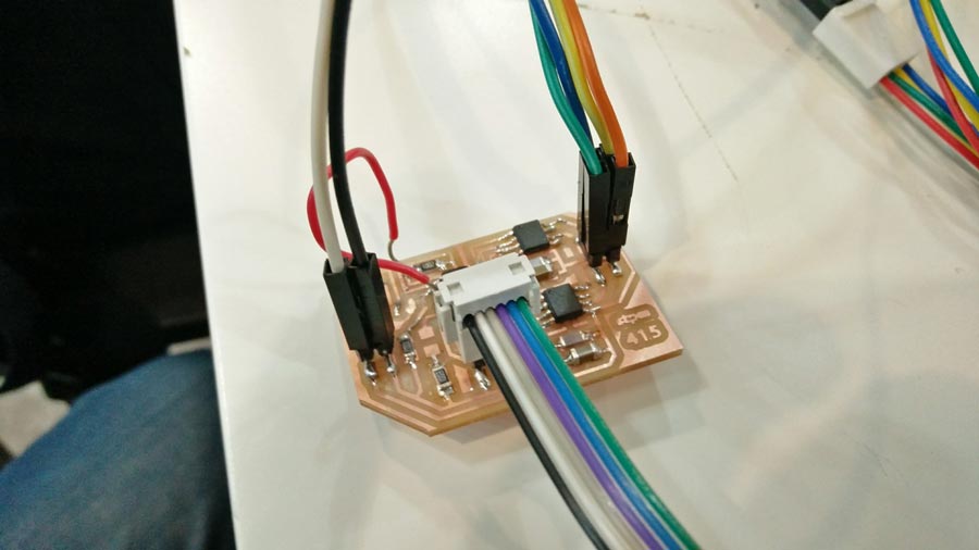
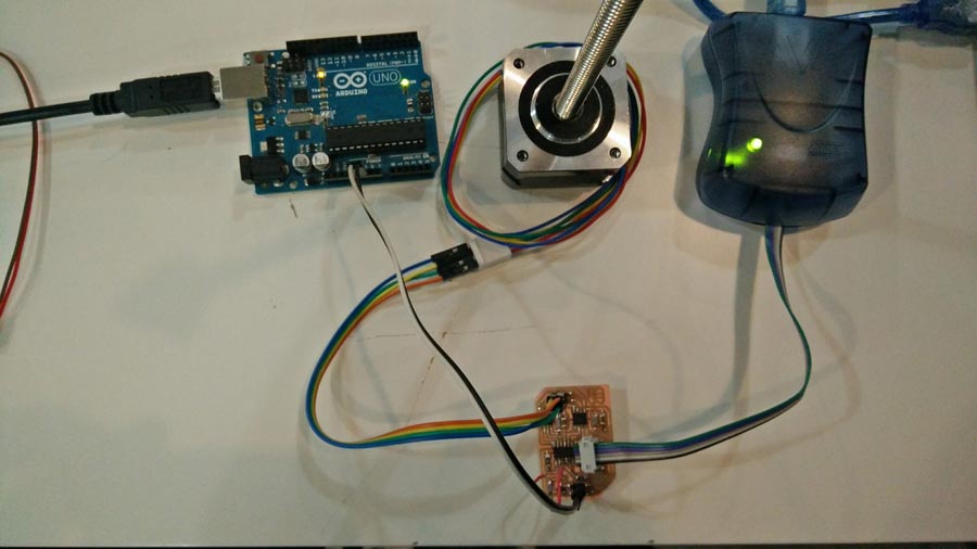
I used the Arduino to power my board by connecting the power and ground of the arduino to the power and GND socket of my board.
I connected the AVRDUDE to the 6 pin header
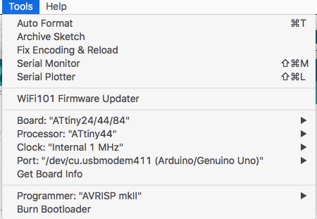
In Arduino IDE I set the "tools menu parameters as follow: (NOTE:The datasheet of the Attiny44 says the internal clock runs at 1 MHz that is why I set Arduino IDE clock to: Internal 1MHz - BUT THAT IS A MISTAKE AND AS YOU KEEP READING YOU WILL SEE THAT CAUSED ME SOME TROUBLE - IT HAS TO BE SET TO "Internal 8MHz" which is how Neil's make file is set to.The Attiny system clock runs a 1MHz only when Low power conumption is in active mode. Otherwise it runs at 8MHz.
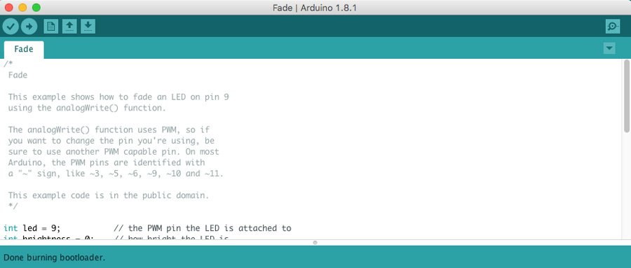
The board connected to the AVRDUDE (green light) but it did bootload (error message: "connection error".) I reviewed all the connections and finally realized I had omitted to trace the RST connection to the PIN03 of the Attiny. I made a bridge and that solved the problem.
Connecting the stepper motor to the board.
I am using a Nema 4 wire stepper motor17. The wiring diagram shows to connect the yellow with blue and red with green.
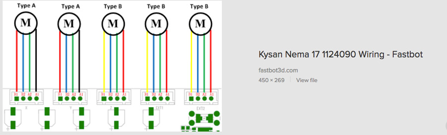
Each pair has a positive and a negative. I connected both negative to the output2 of the H-bridge (A4953)
Programming the board
I felt very lost about the idea of programming so I started looking into Arduino script for steppermotor in Fab academy archive. I found this script but it did not even compiled because the serial port was not declared.
I searched for another and found one that steppermotor code (from Ciltlali Hernandez from Barcelona) that compiled. But it did not make the motor move so I gave up on the Arduino way and decided to follow my intuition and get involve with C code and make file.
I asked my instructor to give a "from scratch briefing" to understand the basic workflow of programming.
The setup of the computer to run .c and .make file should have been done during the 4th week assignment (electronic production) when we first program our fabIsp. I had done it but only understand it partially. My computer has been resetted since and neither the Crosspack AVR and the xcode interface appeared installed.
So I reinstalled them both.
Crosspack avr is a library and xcode is an interface that allows to edit the c code file.
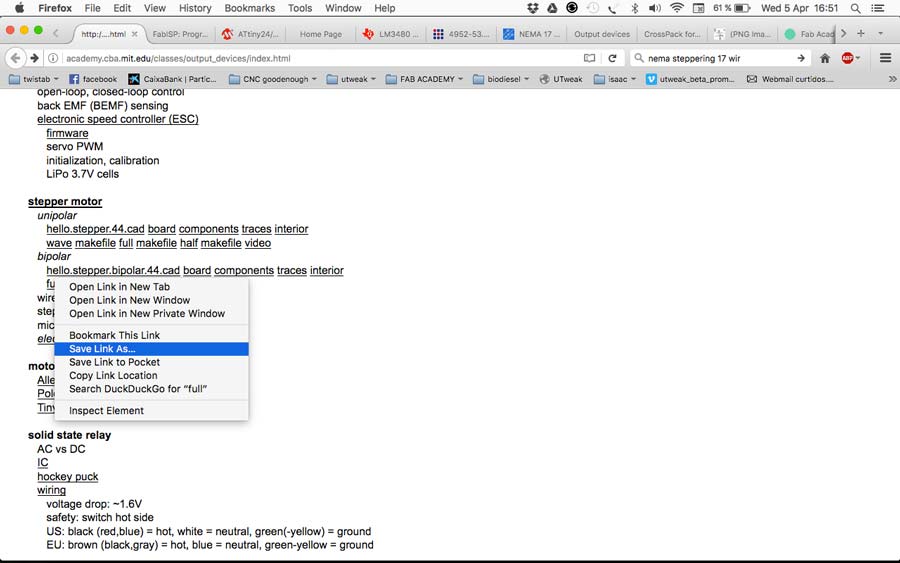
Once this is done I downloaded the C code and the make file (identified as "full" and "make file" in the fab academy page's stepper motor section and saved it in a new folder in my original file folder(desired folder)
The way to do that is:
ctrl right click the file and "save link as" in the desired folder.
Those 2 files appear in the desired folder with their respective extensions. The C file has a .c extension and the make file has a .make extension.
To execute these files, go to terminal, go to the directory (cd ~/desktop etc etc up to where the files are saved.) Once in the directory type "ls" to see the content. That comfirms the .C and .make file are there.
Then type the command to compile the c code from terminal:
sudo make -f hello.stepper.bipolar.44.full.make program-avrisp2
In this command line:
"sudo" is the user identifier (before executing terminal will ask the pw)
"make" is the command
"hello.stepper.bipolar.44.full.make" is the file
"avrisp2" is the programmer used to program the board
(note that the last part of the command is "avrisp2" because that is the command for the AVRDUDE that I am using as a programmer. If I would be using the FabIsp I would add "fabisp" instead.)
Terminal will compile the code and will program the Attiny with it.
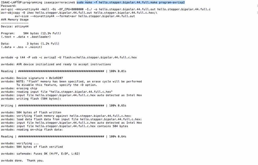
If everything goes well the motor should start running but it did not. It compiled well and when I tried to run it the AVRDUDE blinked orange a few seconds and turned back green but the motor did not operate nor did I got an error mesaage. There was 2 problems going on.
1º- I was trying to make a 12v motor operate with a 5v (arduino) source.
Once I connected the board to 12v the motor started making noise but would not operate properly.
2º- I had changed the internal clock setting in the make file from 8MGz to 1Mgz but that was a mistake.It had to be at 8MGz
With these new settings the motor started doing it's sequence.
Note that once the progrm is compiled and executed there are 2 new files generated in the folder. Those are the executable files and if we make a change in the .make or .c file those need to be ereased and the code needs to be recompiled in terminal to be inserted into the microcontroller (Attiny).

Once the Attiny is programmed there is no need to have the AVRdude (or any programmer) connected. The program can run directly from a power source (in this case the computer).
That is where Python becomes handy because it allows to control the motor/machine from the code directly. That will be my next challenge.