Assignment:
A_Create a 3D object, mould and cast it.
A_Create an object, mould it and cast it.
For this assisgnment I am documenting the 2rubber stamp" I did last year + a new project of a lamp shade.
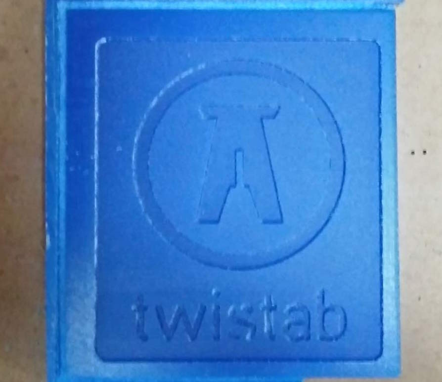
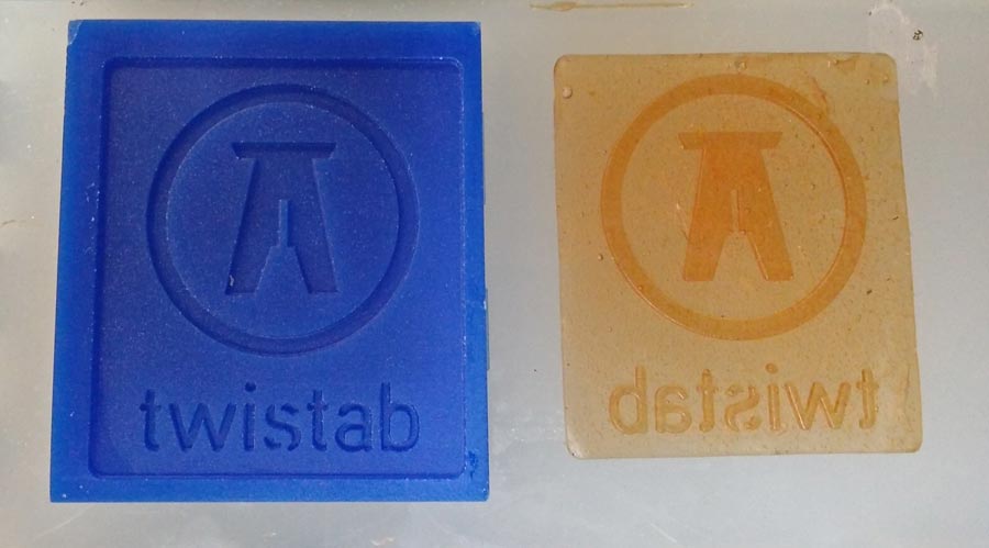
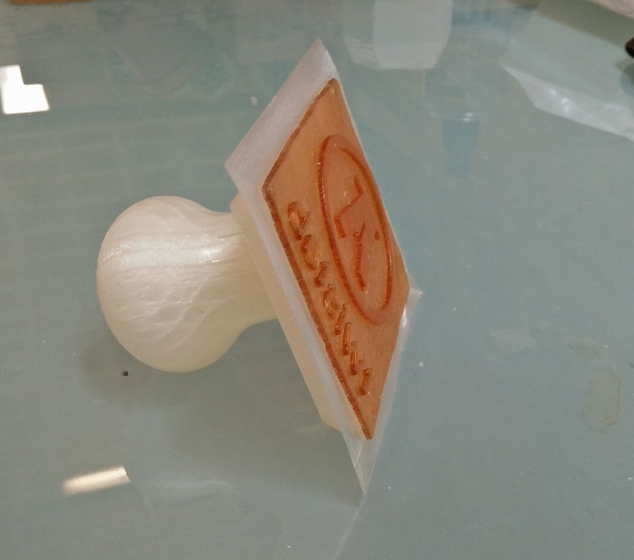
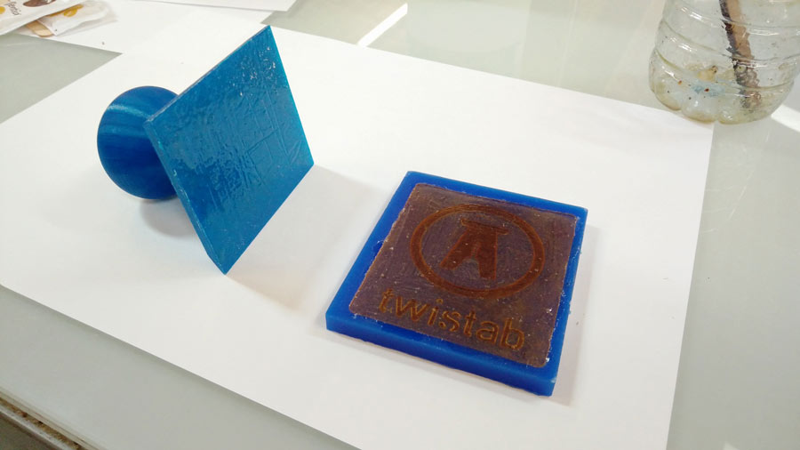
The rubber stamp of the Twistab brand logo was part of last year's assignment for this exercise. I had deliberately decided to do something simple so I can experiement and make shure to complete the assignment on time, learn the basic process and get familiar with molding and casting techniques and materials.
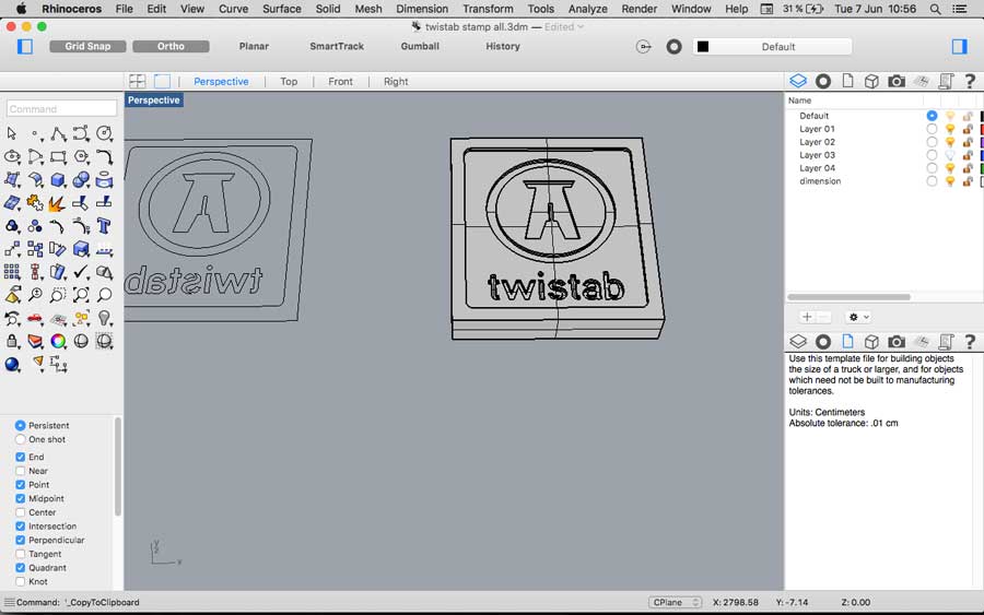
While making the Rhino file I struggled to figure out the positive/negative extrusion so the word "Twistab" would come out the right way when the ink is stamped on the surface.
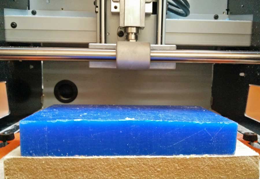
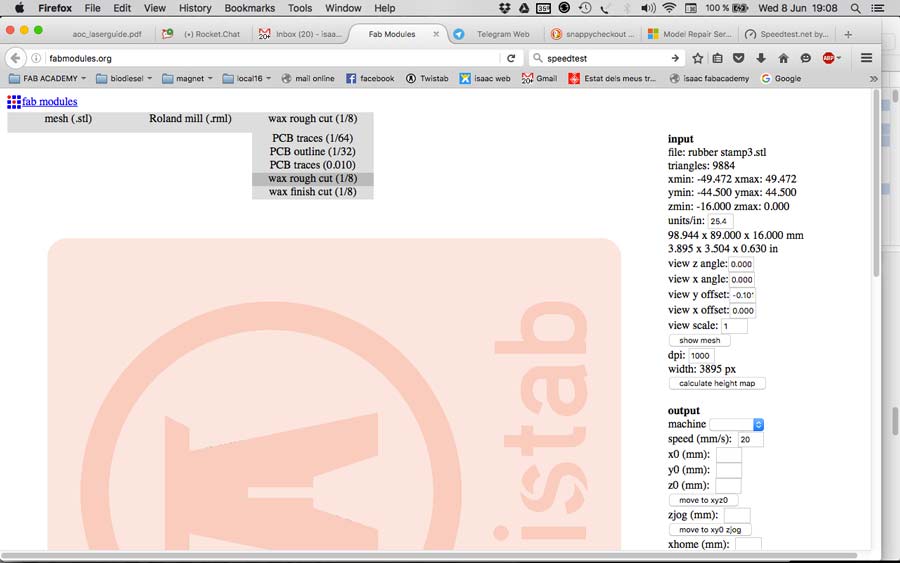
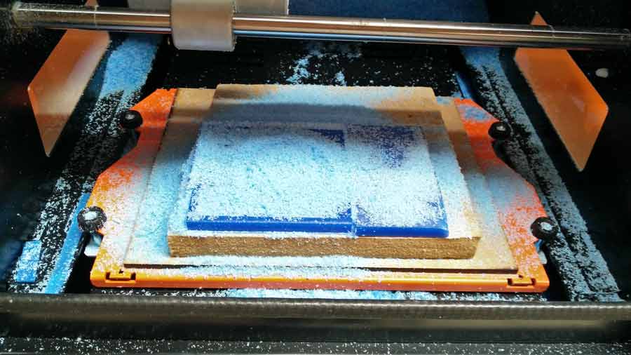
Before milling the actual model I prepared the wax block by flattening it using the fabmodule "rough cut" with 1/8 endmill on a Roland Srm20.
My first attempt was a mold with the letter reversed but I did not casted it because I realized before that the rubber skin cast would result in the word reversed once it is stamped.
I went back to the rhino file and corrected the file according to the following logic:
1º- positive image on Rhino file
2º- negative extrusion milled on wax.
3º- positive wax mould
4º- negative casted rubber skin
5º -positive ink image stamped on surface
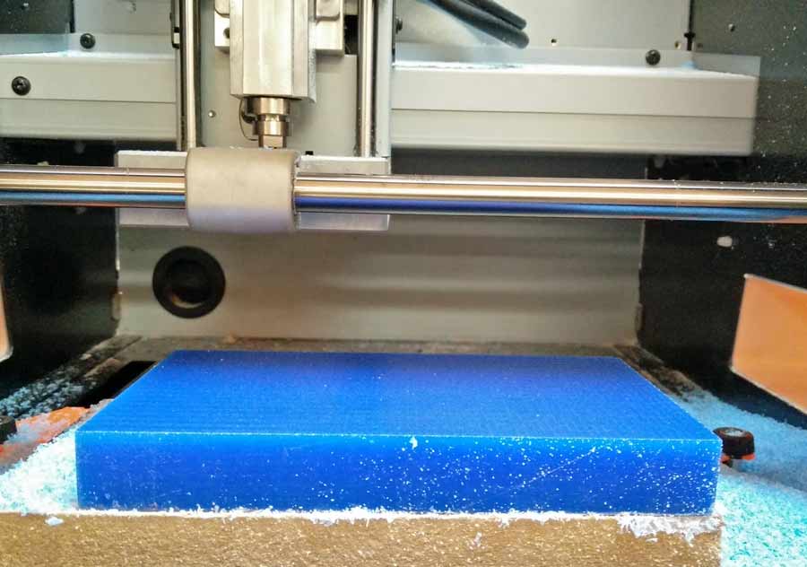
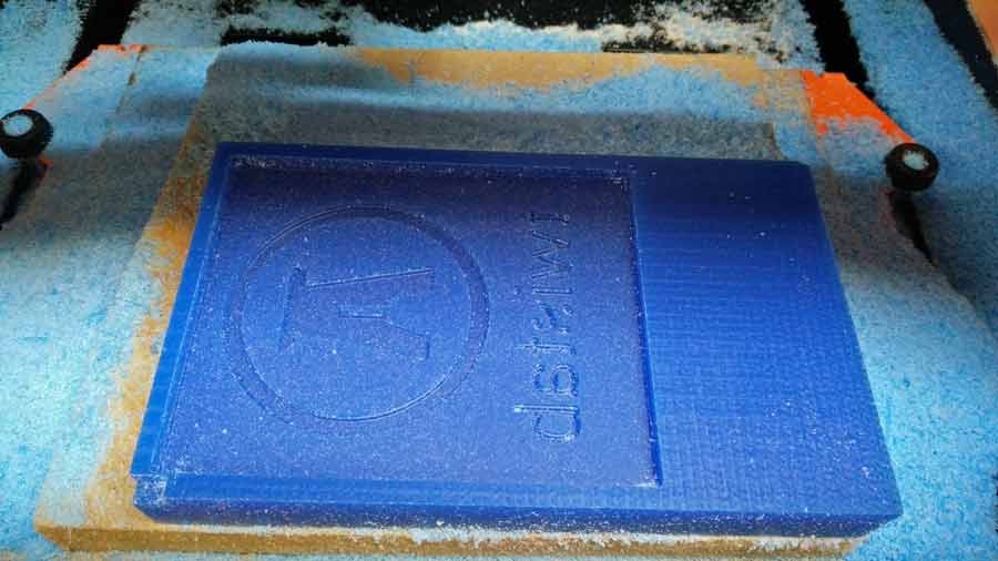
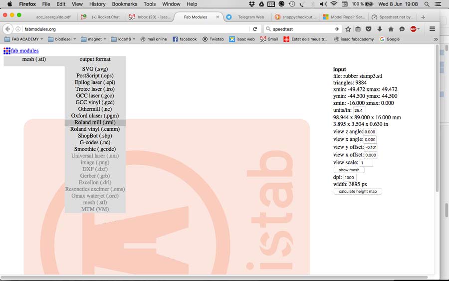
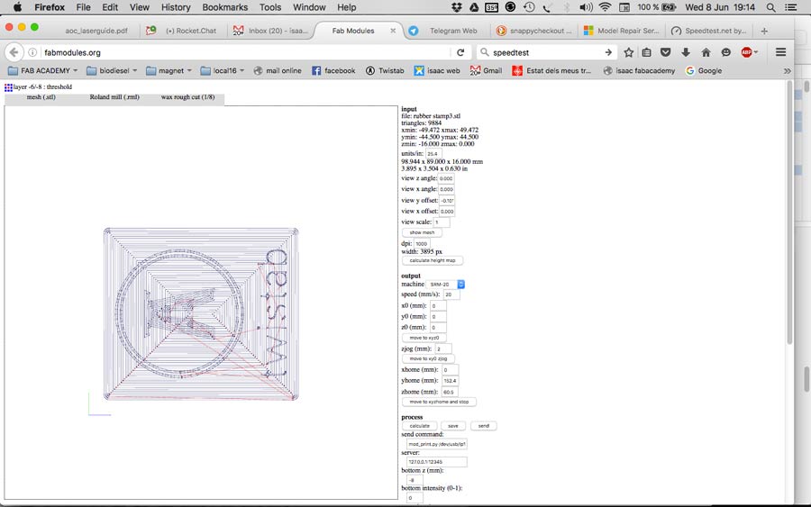
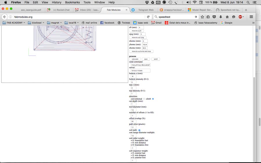
I exported the rhino file as a .stl file and imported it into the fabmodule. Than I made a first "rough cut"and after a "fine cut" also with the 1/8 endmill.
I prepared the milling file using fabmodule to mill on a Roland SMR20. First I did the rough milling and went on with finishing.
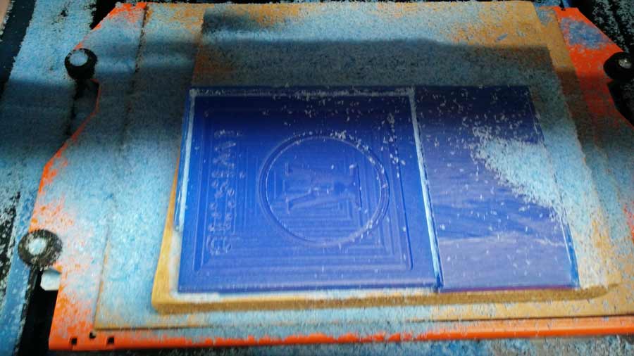
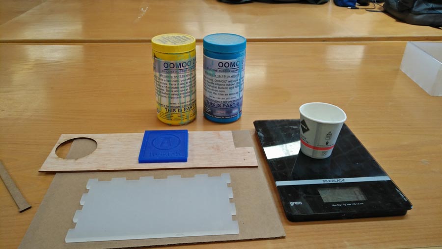
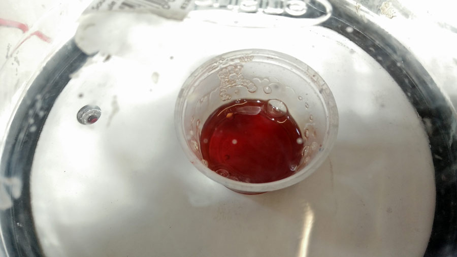
I mixed the Oomo silicone rubber and proceeded with the moulding.
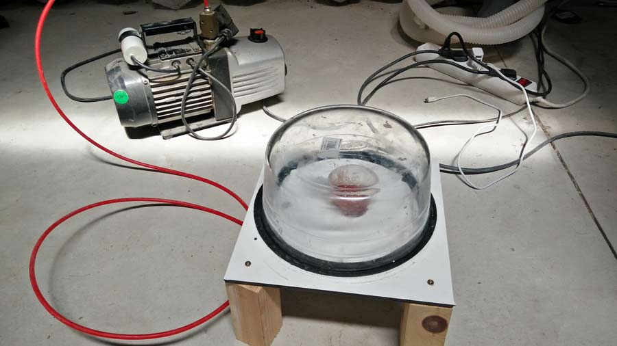
I purged the air bubble in a vaccum chamber. It is quite amazing how many bubbles are stored into this liquid that actually look like transflucid at first glance.
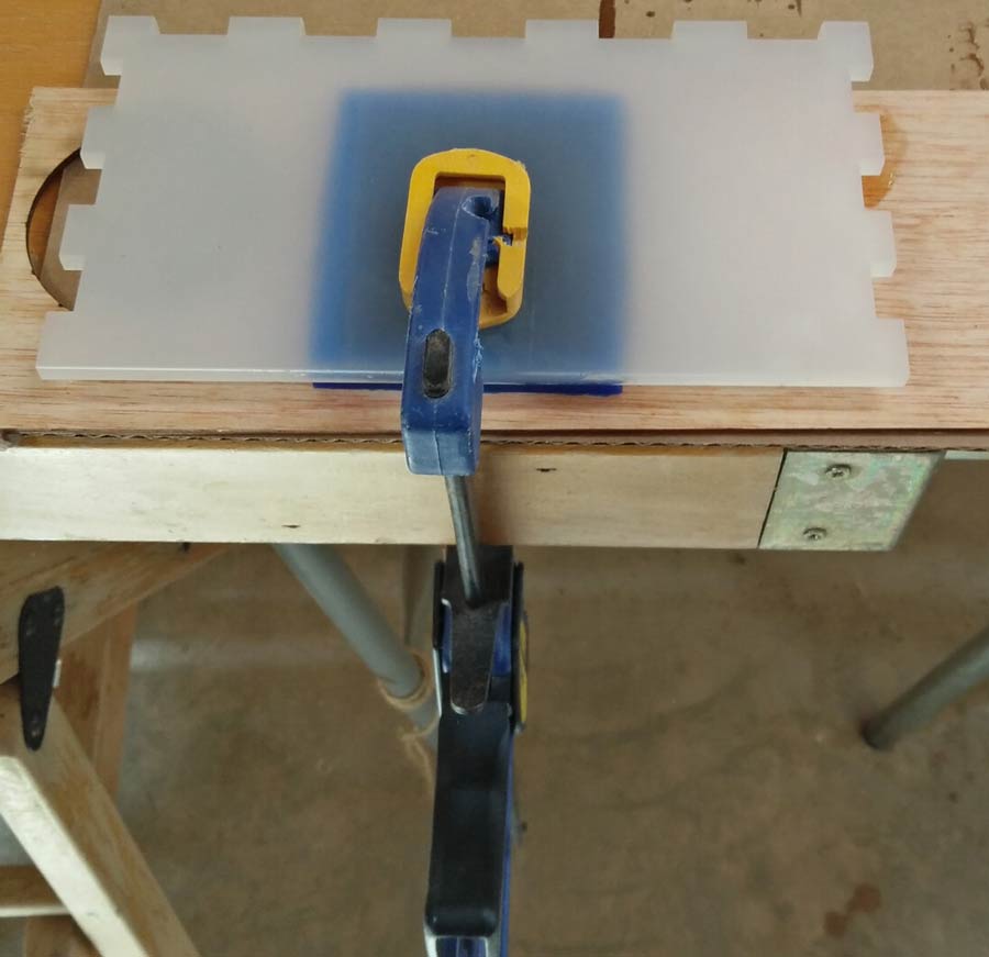
Than I poured it carefully into the mould, covered it with a piece of plexiglass and clamped it to a table.
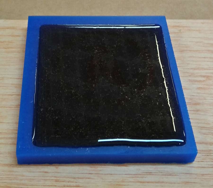
12 hours later (the next morning) the mould was ready. I demoulded it. It came out pretty well. There were some few bubbles in the mold but none in critical area that could affect the stamp quality.
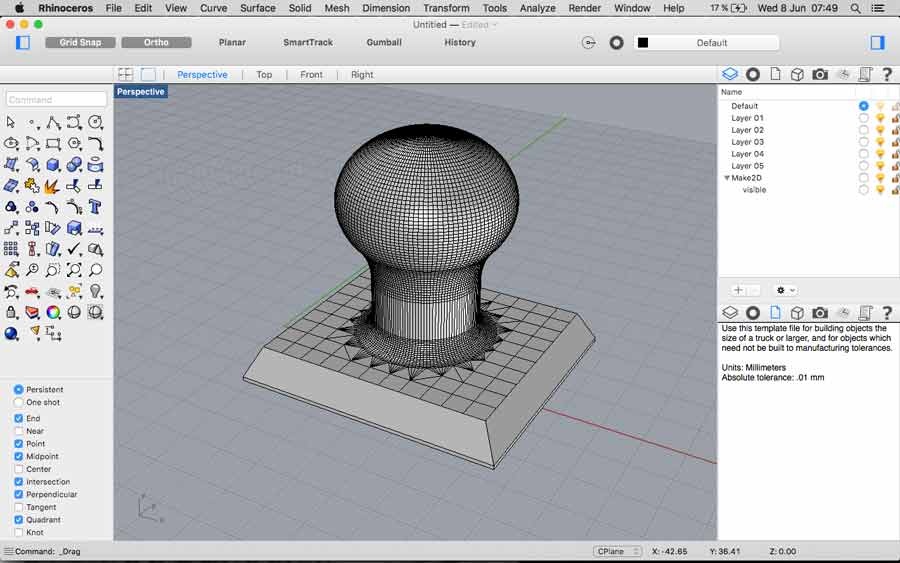
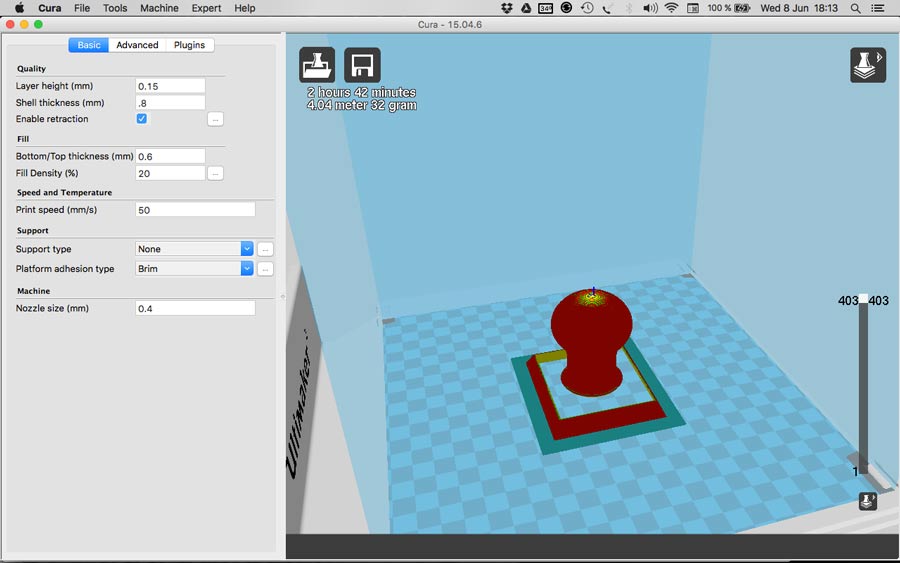
I designed the handle in Rhino, generated the -stl file in Cura and 3D printed using PLA.
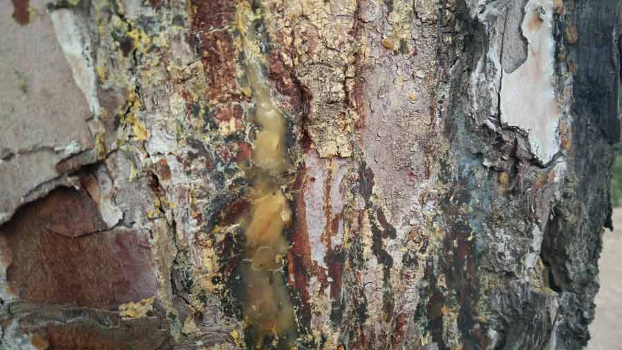
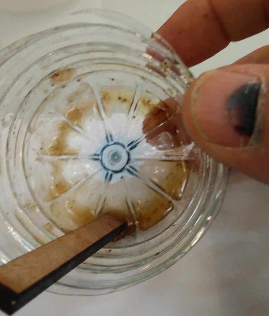
Looking for a solution to join the 2 parts together and wanting to avoid toxic material I decided to experiment with pine resin - I have been curious about it for a while and thaught it was a good opportunity to test it. I went by pure intuition and did not even read or research about it before. Just did it. I collected a bit (50 grams) of pine sap from a pine tree behind the lab, mixed it with 96% Alcohol (1:1 proportion). With a small stick I diluted the resin and the alcohol until getting a pasty liquid.

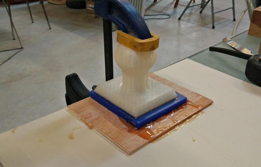
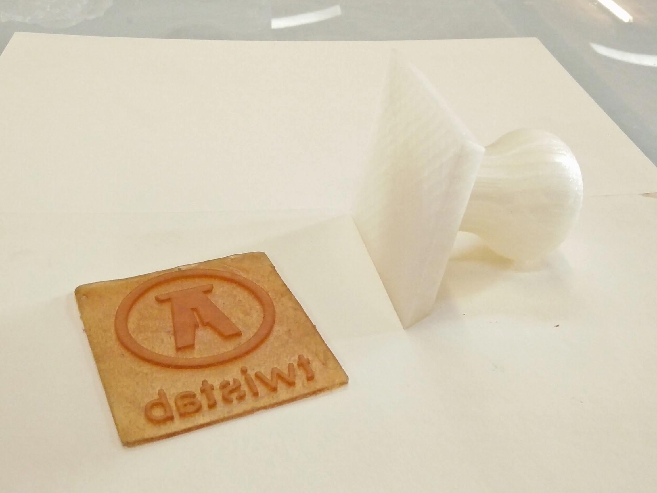
I applied the liquid with a brush on both surfaces, clamp them together and let it sit there for 12 hours. and The result was just perfect- the PLA and silicone rubber bounded strongly.
There had been a problem with the 3D printed part/handle - filament got caught in the line and print aborted almost at the end (94%), so I decided to repeat the whole porcess to make a 2º stamp
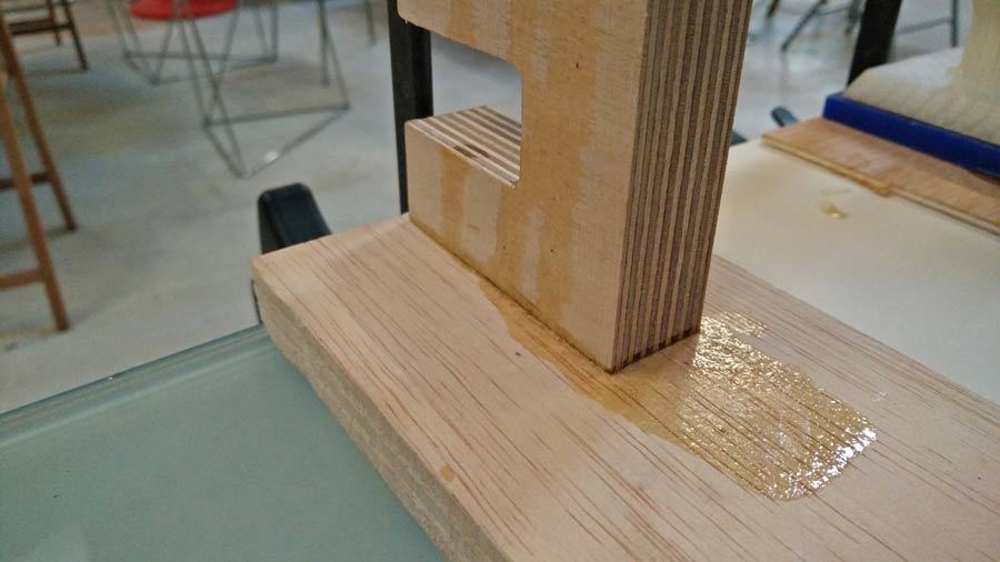
Excited about the pine resin glue solution I tried to bound 2 pieces of plywood with the same solution but it had no strenght. To be continued......
Designing and 3D milling for moulding and casting
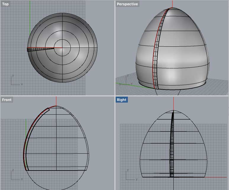
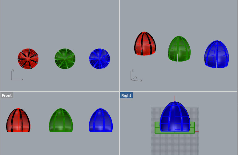
To explore milling in 3D I made a mould for a lampshade that I will produce for the composite assignment. The idea is to make a lamp shade with thin and transparent material (preferably organic such as wood but can also be recycled paper) with enough rigidity so it keeps the shape by stacking different layers one on top of the others. By stacking moulded shape of different colors I am intneding to create different hues of transparency.
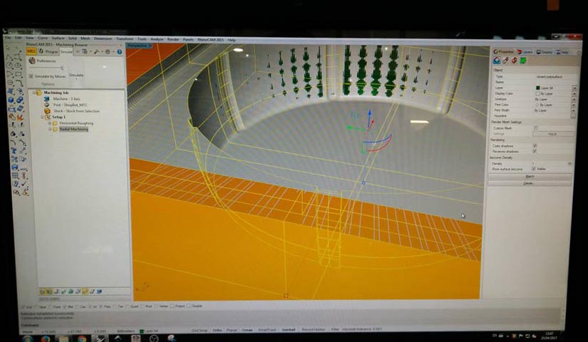
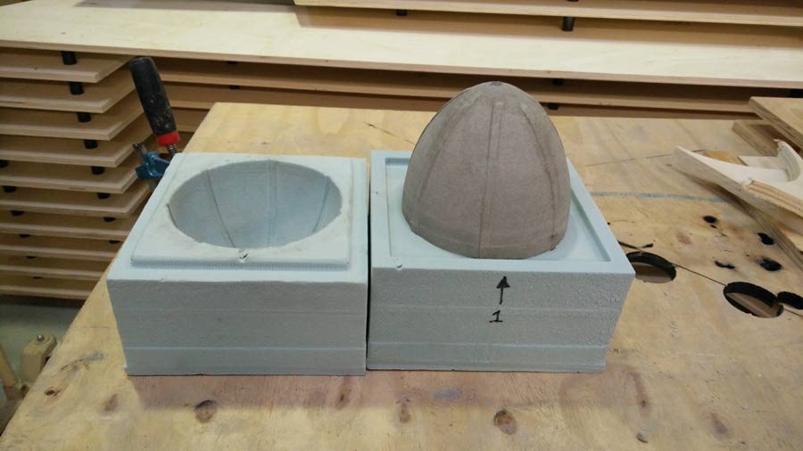
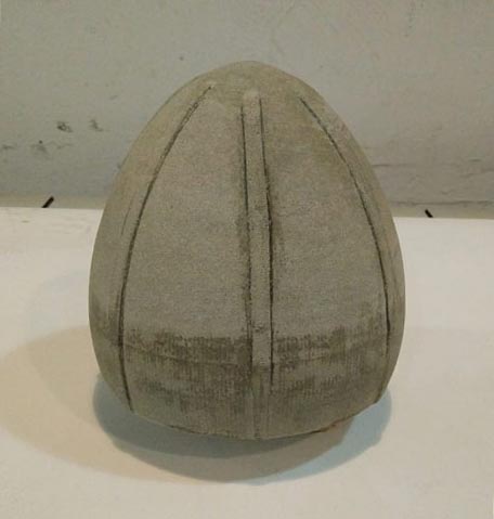
I designed the mould in Rhino using the generic shape of an egg as a base. (I would have prefer to use a parametric application but I don't feel comfortable enough yet to enjoy the designing process with grasshopper - I'll come back to this in my conclusion)
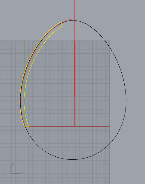
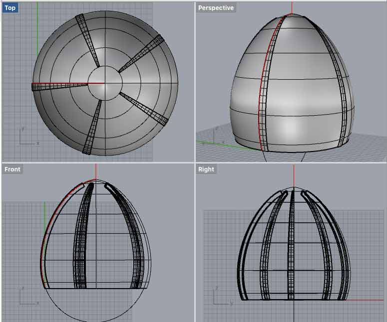
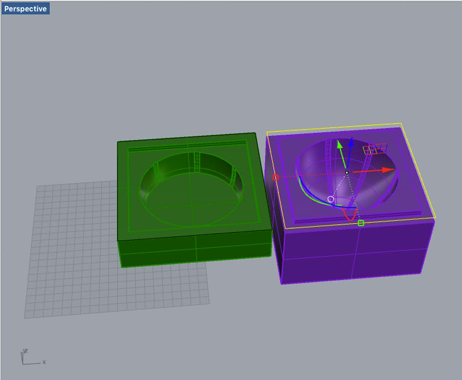
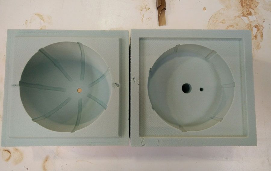
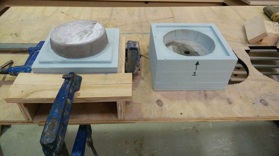
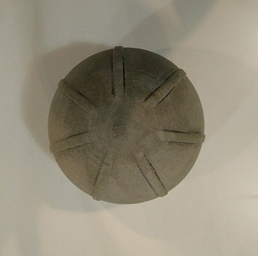
The mould is split horizontally in 2 parts. The union of the 2 pieces has an horizontal offset so milling can be possible. No negative vertical angle. (see image).
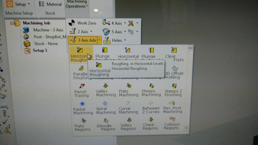
I documented the making of the toolpath because it was the first time I mill in 3D. We did a rough extraction (5 minutes.) and a fine milling with a 75% overlap of the mill path (35minutes).
It came out very well - as expected. The ball end mill bit could not make the 90ª angle of the grooves in the main structure.
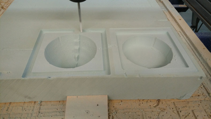
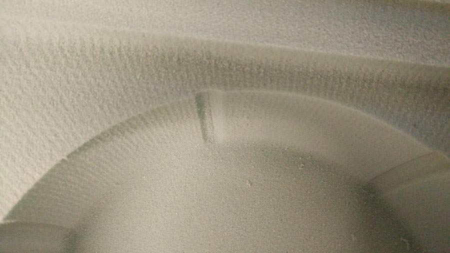
It would require a very small endmill to do that. No matter I retouched it manually with a file. (I am not even shure it will be necessary to have any groove in the final design.) This iteration is a test and it is ok if it comes out with some mistake).
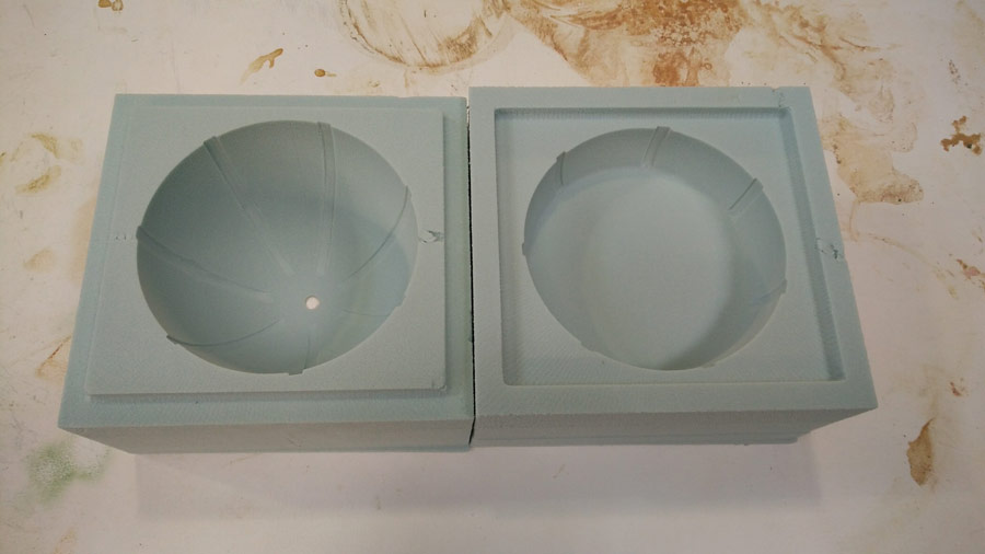
I made a big and a small hole at the bottom of the mould. The big one is to pour the concrete in the mould and the small one to evacuate the air. I sprayed the interior part of the mold to seal the porosity of the foam. Put 3 coats, letting it dry 15min. between each coats.
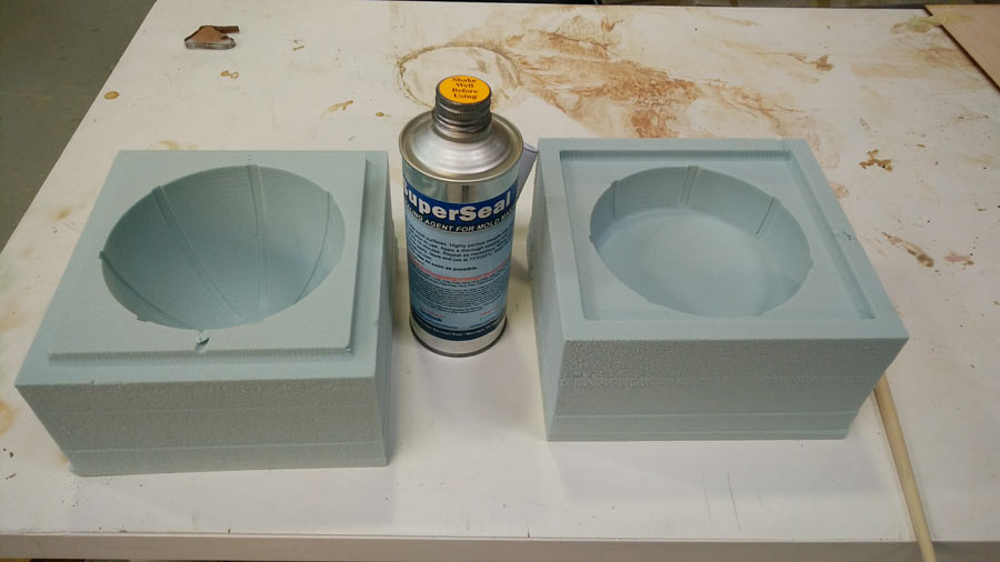
I sanded a little bit the slotting part of the mould so it would sit in all the way. Because of the ball endmill the cormer was not 90ª so I just rubbed off the top corner of the male surface.
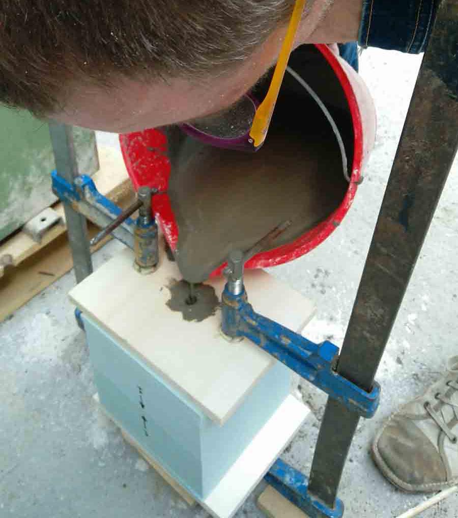
I clamped it, putting a piece of plywood on both ends.
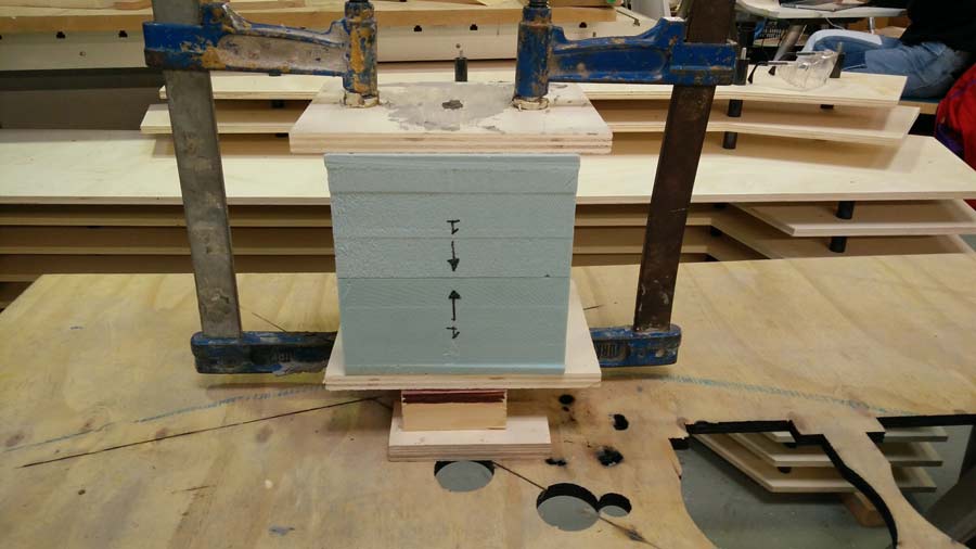
I prepared the microcement mix - just cement and water, and I poured it in slowly.
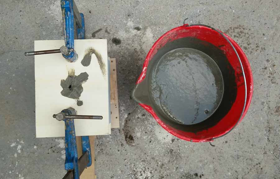
I let the cast sit for 12 hopurs before demoulding.
When I opened the mould the casted part was hot. The foam acted as an isolation material and all the energy released by the cement remained inside the mold - a sign that it was pretty air tight.
The bottom part relaese fairly easy. I clamped the mould to a table and pull gently but with strenght.
But the top part was a different story. I wanted to save the mould. I managed to pry the casted piece out of the mould.
The mould was in perfect shape after demoulding. And the casted piece came out almost perfect. The cement did not fill the mould completely leaving the bottom edge slightly uneven. I had to file the corner of the groove and the seam marks.
I can move on now to start thinking about the material I will use and how I will cast the composite onto that mould.