<-- Week 12
WEEK 13
[ INPUT DEVICES ]
Week 14 -->
WEEK'S GOALS:
ACHIEVEMENTS THIS WEEK:
(i) INPUT DEVICES
1. MOTION DETECTOR-PIR Sensor Module with own board.- Helps sense motion over a distance and by intensity
- Switch off LED when motion detector PIR Sensor doesnt sense movement.
- Executes an SMD LED on pressing the button
- Interated within the board.
3. IR sensor as an input to Atmega 328 board
(ii) OUTPUT DEVICES:
1. Pizo-Buzzer- When the board's IR or PIR detects movement, the buzzer sounds in a given pattern
- When the board's IR or PIR detects movement, the LED lights up in the same pattern as the buzzer
- Using Firefly and Arduino, managed to make the servo rotate directly through a firefly INterface. Note: Board used was arduino for this one case.
TASKS AT HAND:
NO PENDING TASKSWEEK's START:
So this week started with Neil having asked Vigyan ashram students to check the way they mill a PCB since none of them were getting neatly milled boards. Havnig managed to get good results from the old Modela, Suhasji asked me to explain all others in deep the proper way to mill and tips regarding customised boards among other settings and arrangements on the modela. So the first two days went by teaching others everything there was to the older modela and all about the offline version of MODS and each of its settings in deep. Am glad that no board since then at VA went milled with any rough surfaces to them and the no. of bits that broke reduced too.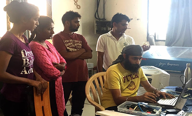
NOTE: Vigyan Ashram is known as "Fablab 0" , it is one of the remotest labs with very minimal internet access , therefore, we have been using old version of Fab module which is an offline version.

(i) INPUT DEVICE as IR with (ii) OUTPUT DEVICE as Buzzer
Final Electronics: Obstruction Detection Sound System x 2 boards
I designed a cuboid kit for my final project where in i designed my own board with atmega328 IC. In the video above, you will see an Ir sensor connected with my board pin headers IR sensor (GND, VCC, DATA PIN), then two pins of buzzer (GND, SIGNAL) connected to the board and lastly, my own FABISP connected to the board's (GND, RESET, VCC, MOSI, MISO, SCK) for power and programming before. In this cuboid kit i basically later included switches so that every switch can be used for a specific board assembled in the cuboid.
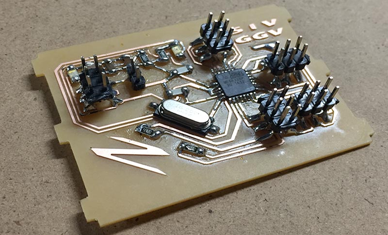
In above picture, you will see my final project and my output/input board of Atmega 328.
(i) INPUT DEVICE as PIR with (ii) OUTPUT DEVICE as LED
In the video below you will see i am using my designed board of Attiny 44 which has pin header, programming pins, resonator and IC for sensors i plan to use both Ir sensor and Motion sensor.
Final Electronics: Obstruction Detection Sound System
In the above video, you will see i am doing Motion sensor with my another ATTiny 44 input board.

STEPS to make this board:

Using Fabisp to program it

Motion Sensor which has three pins GND, VCC and data pin which i connected to my Attiny44.


Above images are my cut file and trace file for my Attiny board 44.


Design Process:
Importing File:
Milling:
Soldering:
Programming:
Finally I needed to make my makefile and for that i coded in the Arduino IDE-complied it and then did 'MAKE' with the makefile from its location in GIT bash through my board ,
(iii) INPUT DEVICE as PIR with (ii) OUTPUT DEVICE as LED on ARDUINO


Setting up Arduino:
CODE:
So my codes are below:I took them from internet first but while I was uploading it showed “ serial undefined”, after repeated trials I preferred coding myself referring the previous one with no Serial.
FTDI Pinout
Codes tested
MOTION SENSOR with LED

