Electronics production
Assignment
- Make an in-circuit programmer by milling the PCB.
- Program it, so that you can use it to program your board in Electronics Design week, and in other weeks.
- Optionally, trying other processes.
Learning outcomes
- Describe the process of milling, stuffing, de-bugging and programming.
- Demonstrate correct workflows and identify areas for improvement if required.
Have you
- Shown how you made and programmed the board.
- Explained any problems and how you fixed them.
- Included a ‘hero shot’ of your board.

Materials
copper board
drill bits

Gerber files
-
Since we still don't have the milling machine in the lab, we visited Ima6ine where we were introduced to the milling process, and our first pcbs were going to be milled there.
For the process of creating the files with the instructions for the milling machine, FlatCAM was used, but before that, the png file was converted to a gerber file with imagetogerber.jar.
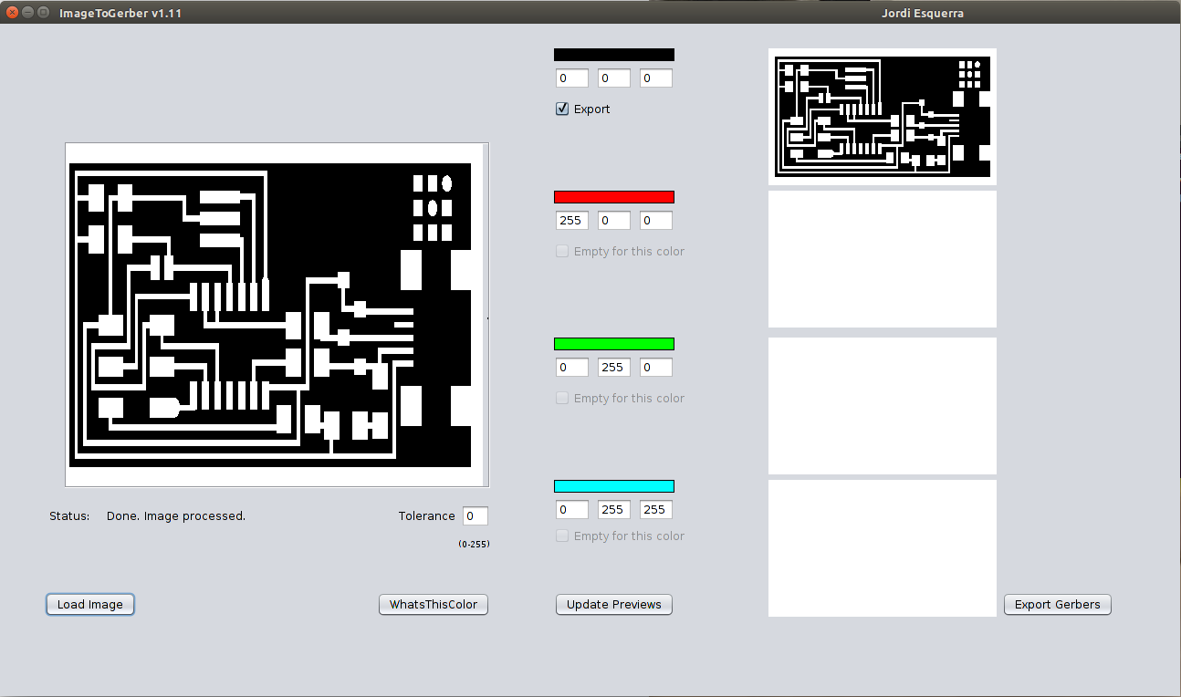
The gerber files can also be directly created from Eagle software.
G-code files
-
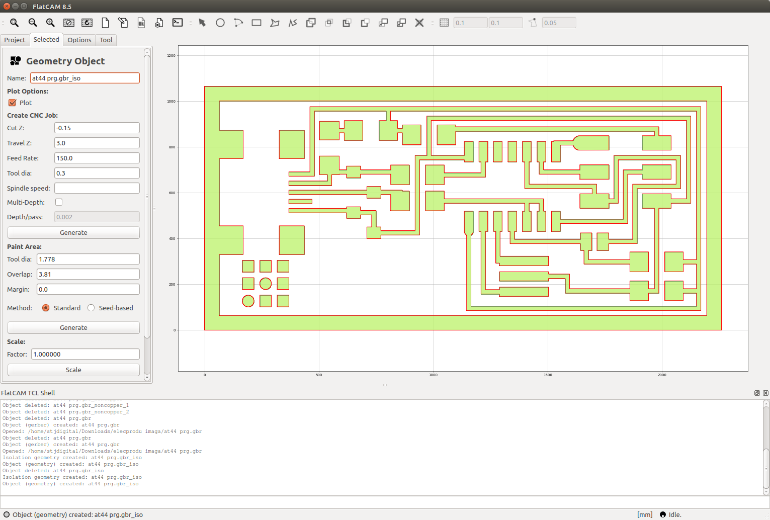
The gerber file created is imported into FlatCAM. The traces are redrawn from the gerber. The first step is to set the units for the project, in our case is mm, after, configure the tool diameter to 0,3 mm for the isolation route, then generate geometry object.
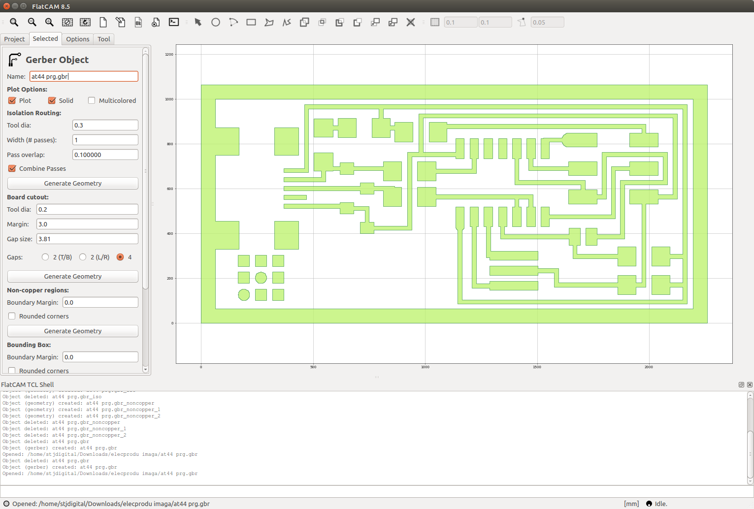
Once the geometry object is created, you can inspect that the route goes parallel to all the pcb routes, effectively isolating them. Then, other variables must be set to create the cnc instructions files:
- Cut Z: -0,15 (depth of carving).
- Travel Z: 3 (height of the tool when not cutting).
- Feedrate: 150 (speed of the tool while cutting in mm/minute).
- Tool diameter: 0,3 (the same as in the previous step).
When the button generate is clicked, it creates the g-code for the isolation route of the pcb. It must be saved with .nc extension.
Following the same steps, the g-code for non copper areas and board cutout can be created. For the board cutout, more depth is required, as well as another tool apropriate for cutting.
Preparing the milling machine
-
The milling machine must be prepared with the right tool. The board must be tightly attached to the bed using double stick tape and clamps.
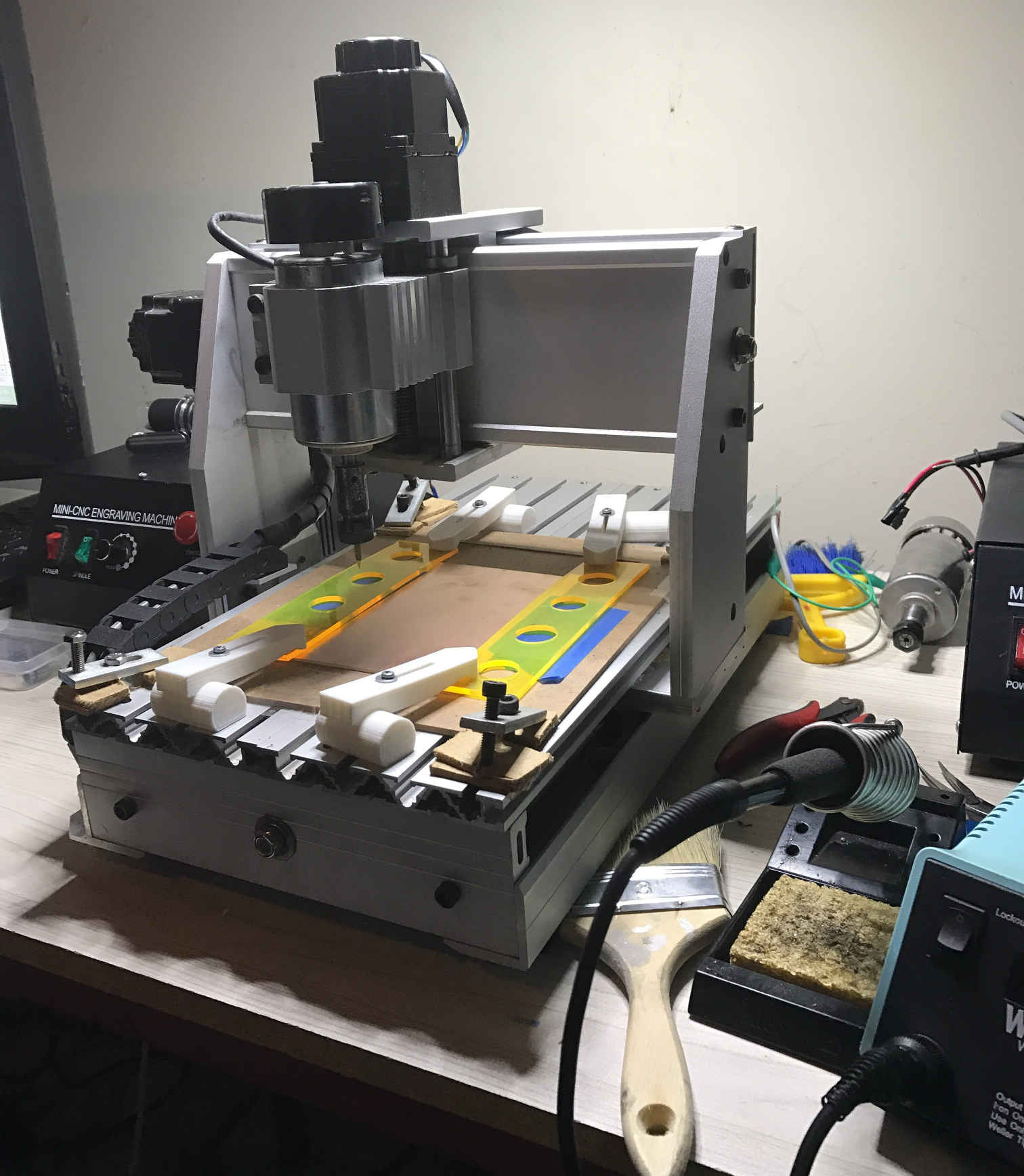
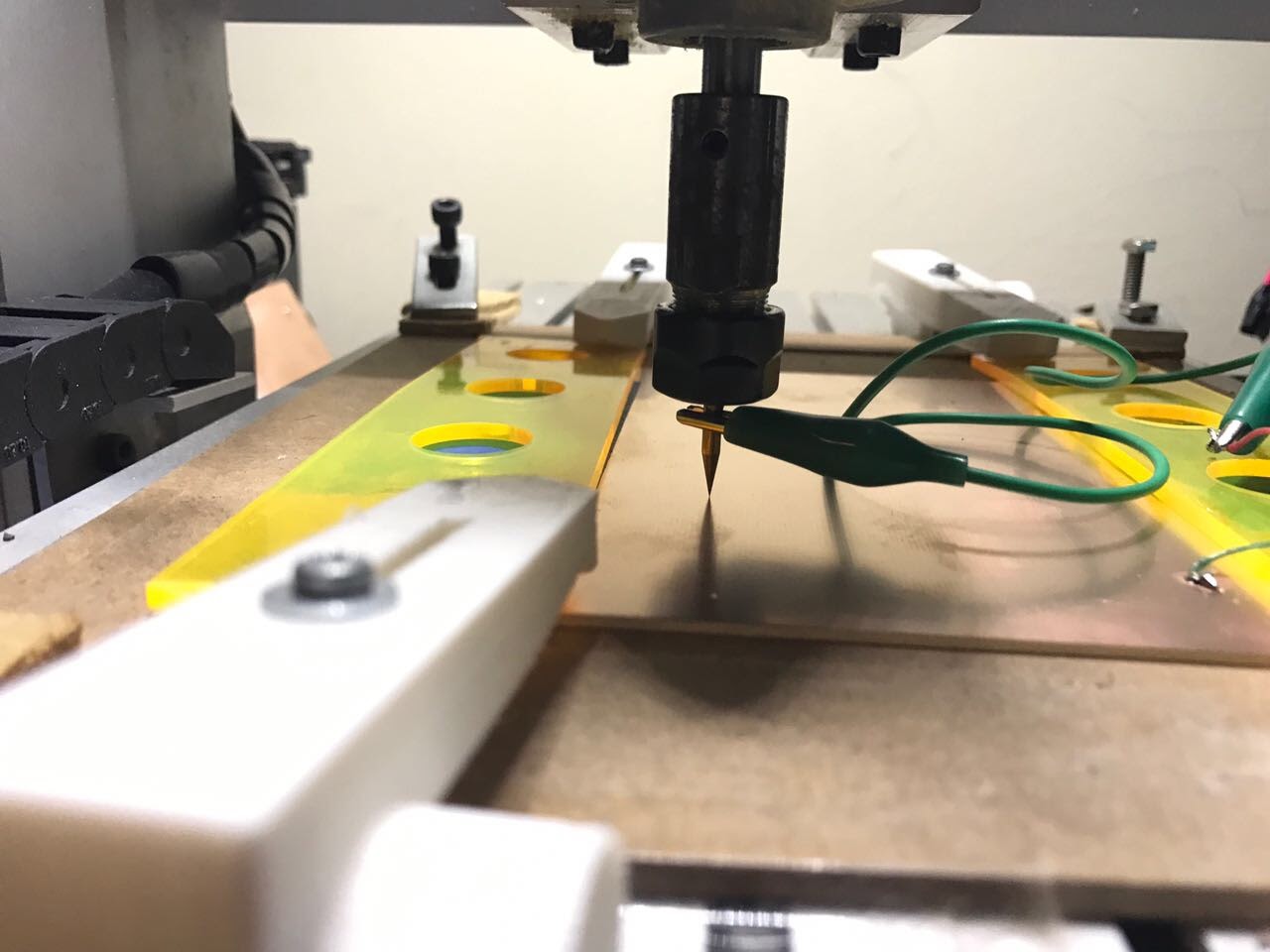
Because the bed may not be leveled, and the pcb may not be completely flat, it`s recommended to set multiple zeros. Current continuity can be used for zero setting, so, a cable is soldered to the board and another cable is connected to the tool, so when there is continuity, a zero is set.
Sending the g-code
-
For the execution of the g-code in this machine, the file is opened with bCNC.
bCNC has the autolevel option, and several zeros are set for Z axis.
The g-code file is opened in bCNC, and, before starting the job, a visual check of the machine is performed, the pcb must be aligned and firmly fixed, there must be no objects between the tool and the board.
If everything is clear, the job can be started.
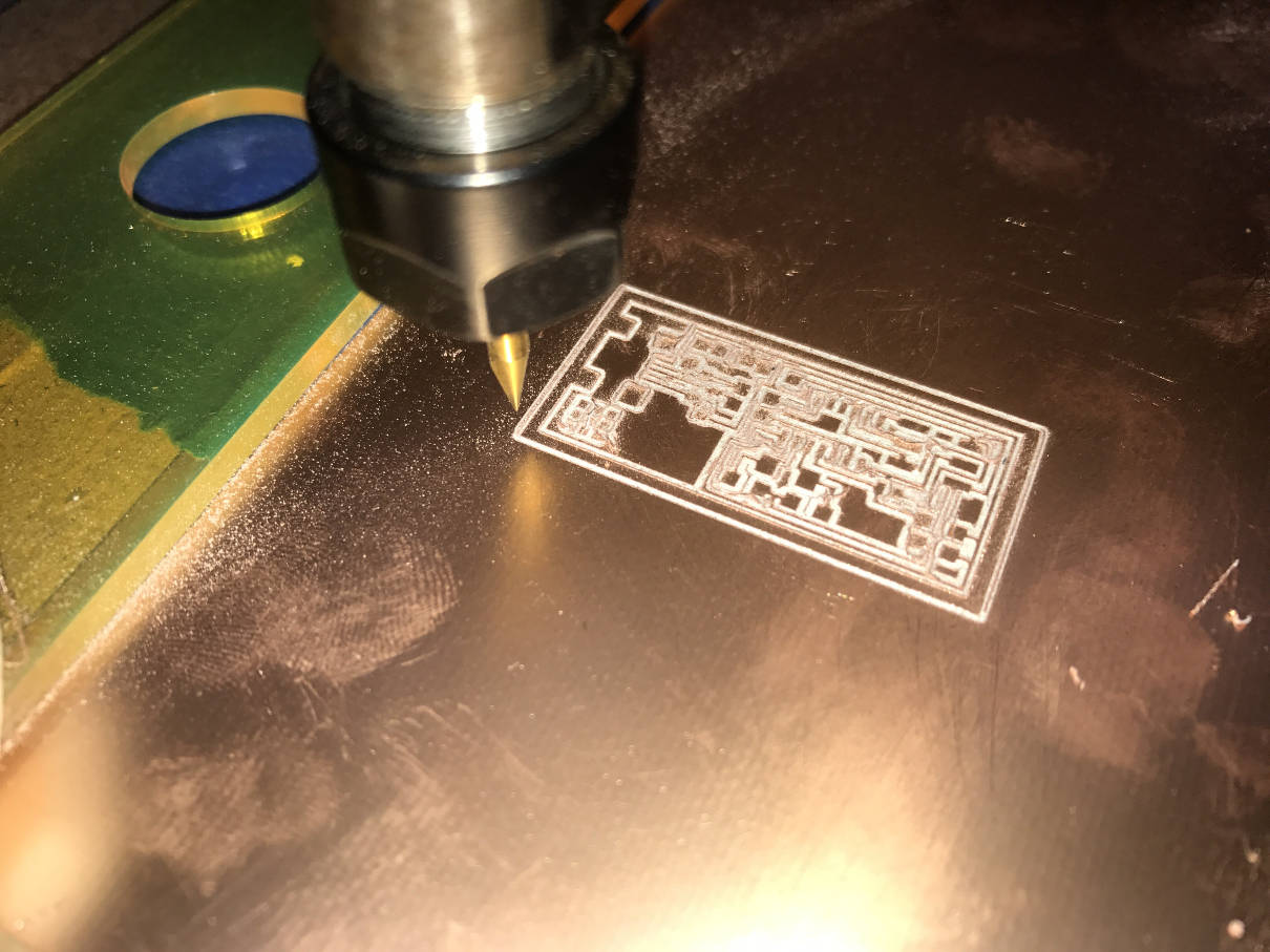
This is the board after isolation route job:
When the isolation route is done, the tool is changed, either to cut the board or to mill non copper areas. Whenever there is a change of tool, it`s good practice to reset the Z axis` zeros.
The two tools used for this board:
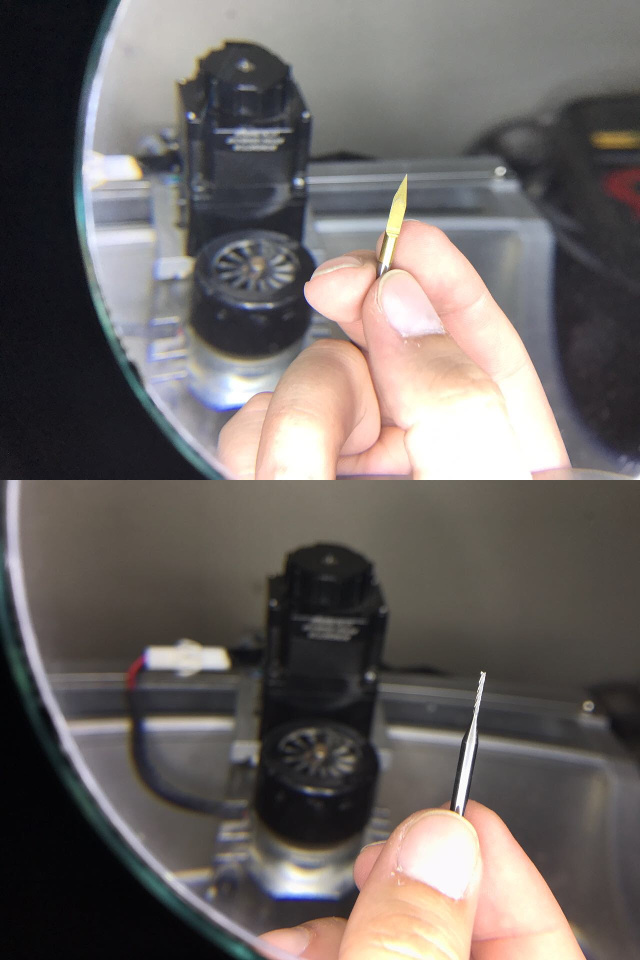
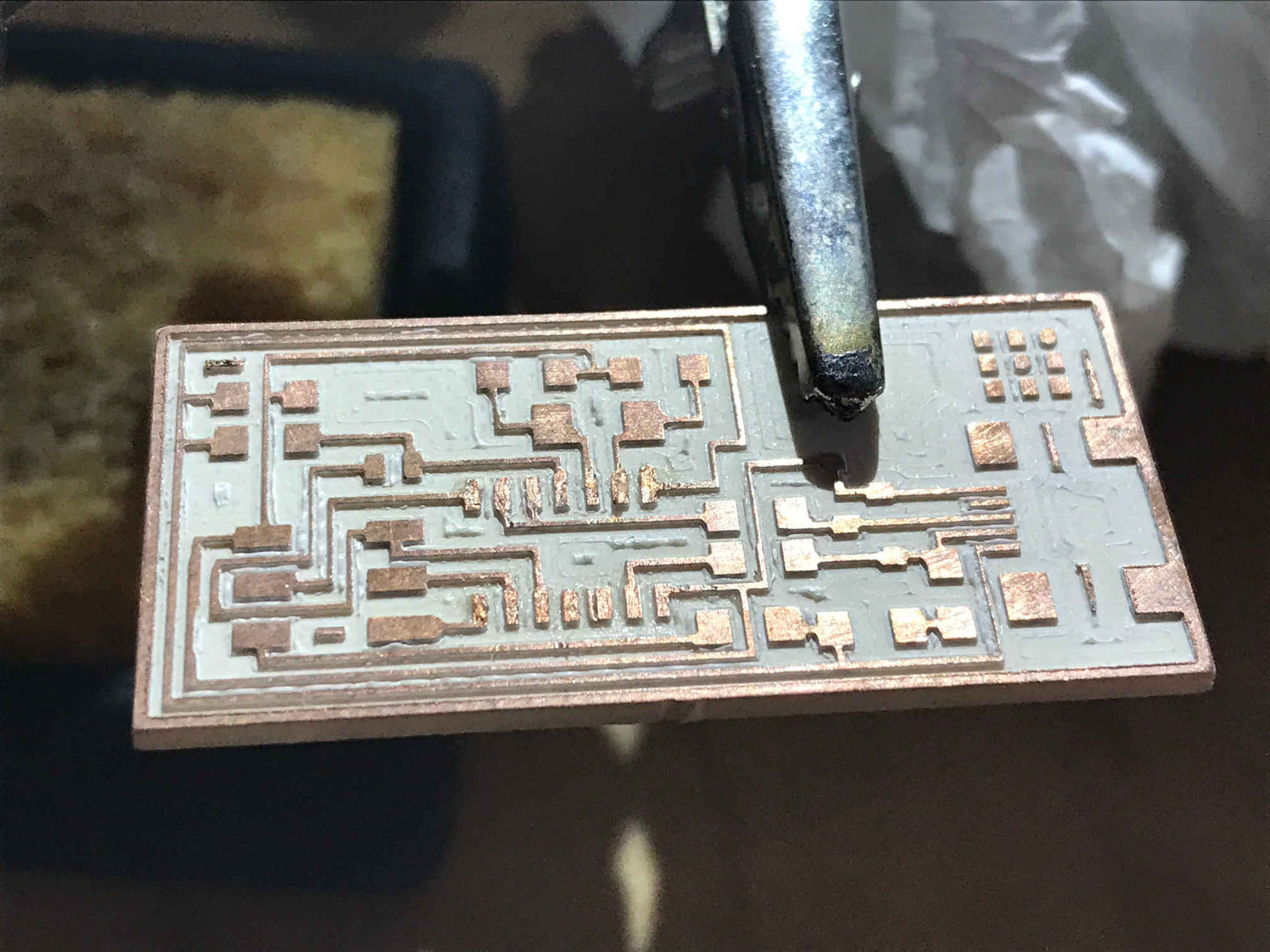
The board after non copper job:
After this, the cnc stopped, and we were unable to continue the process. The boards were sent to us a few days later for soldering and progarmming.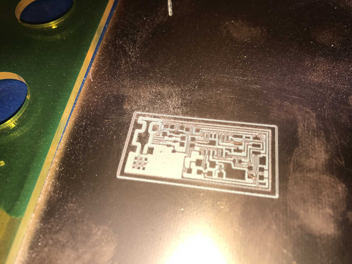
Soldering components
-
Soldering components must be done slowly and precisely, in order to have a good alignment of the components with the traces, have a good connection to the board and get a good finish with the solder. Also, it's very important to avoid solder bridges.
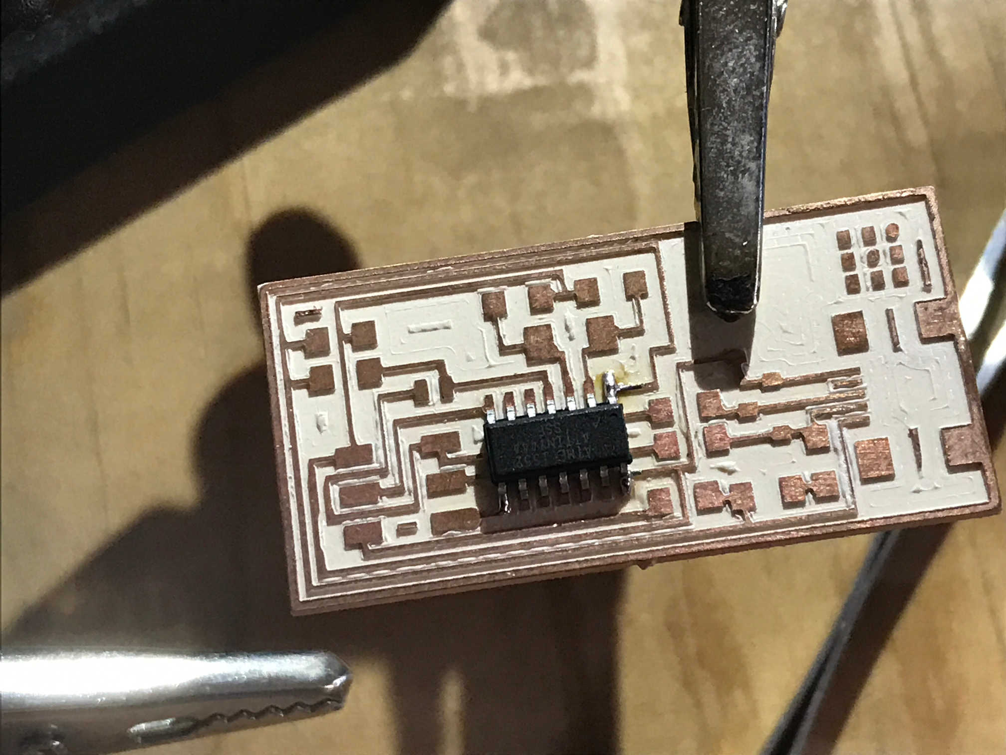
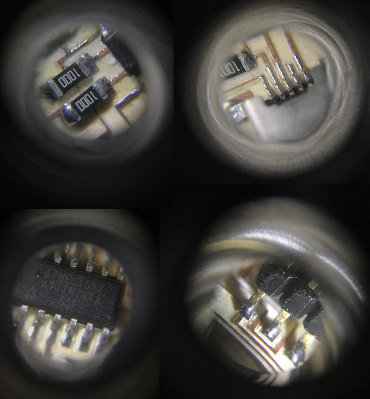
I started with the microcontroller:
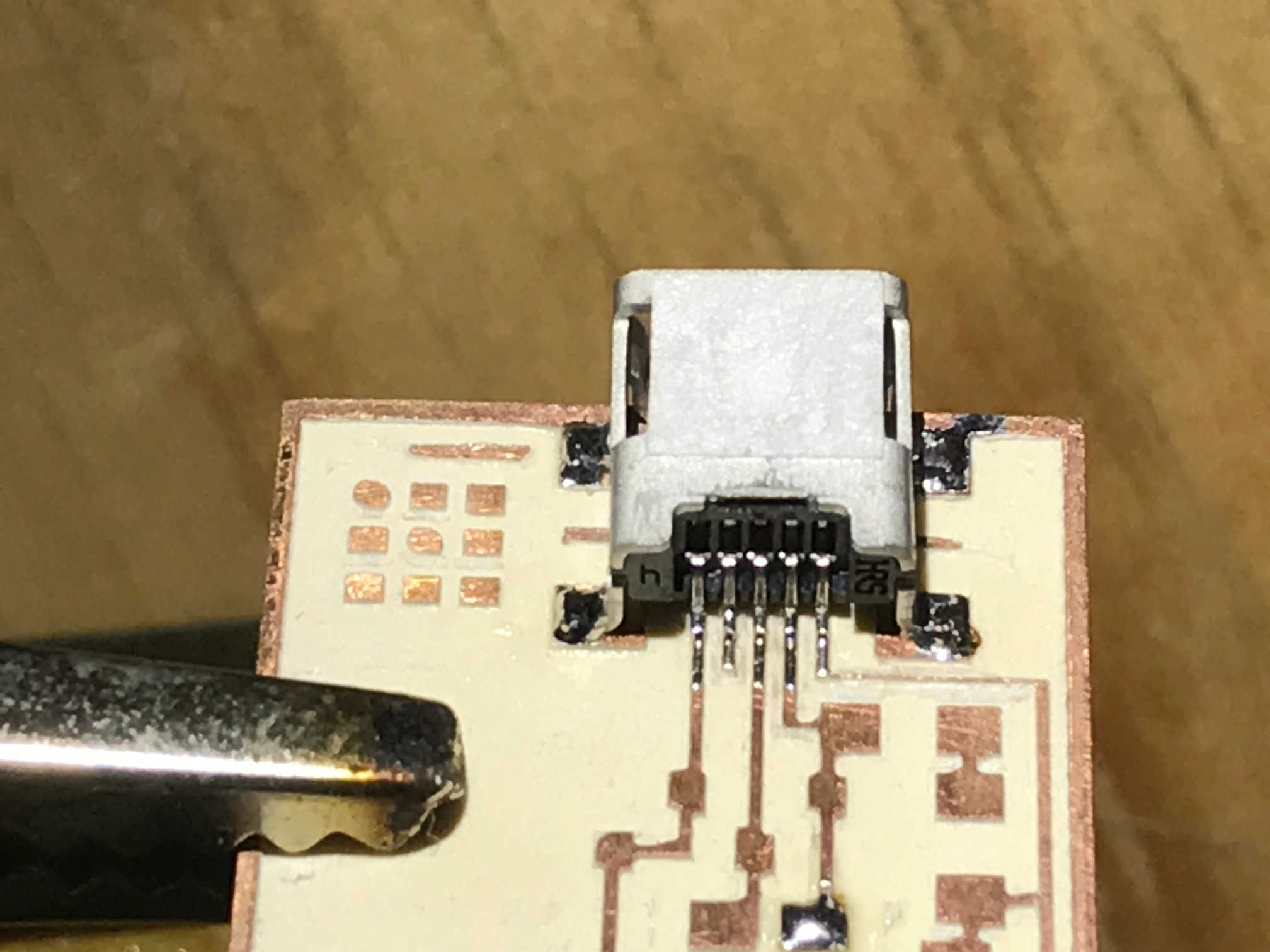
Then the usb port (using solder paste really gives good results):
Then resistors, diodes and capacitors:
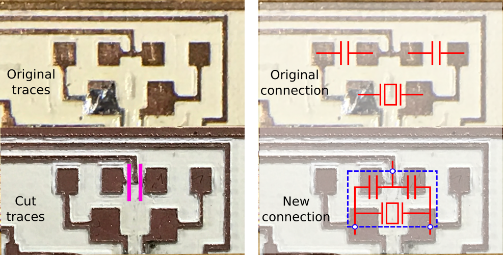
There was a problem with the resonator. We had a 20MHz resonator but it did not fit the routes in the board, and the one that fit, already has internal capacitors. So we modified the board traces. We cut the two capacitor traces to ground by cutting on the pink marks, then, connected the resonator to the three points required.
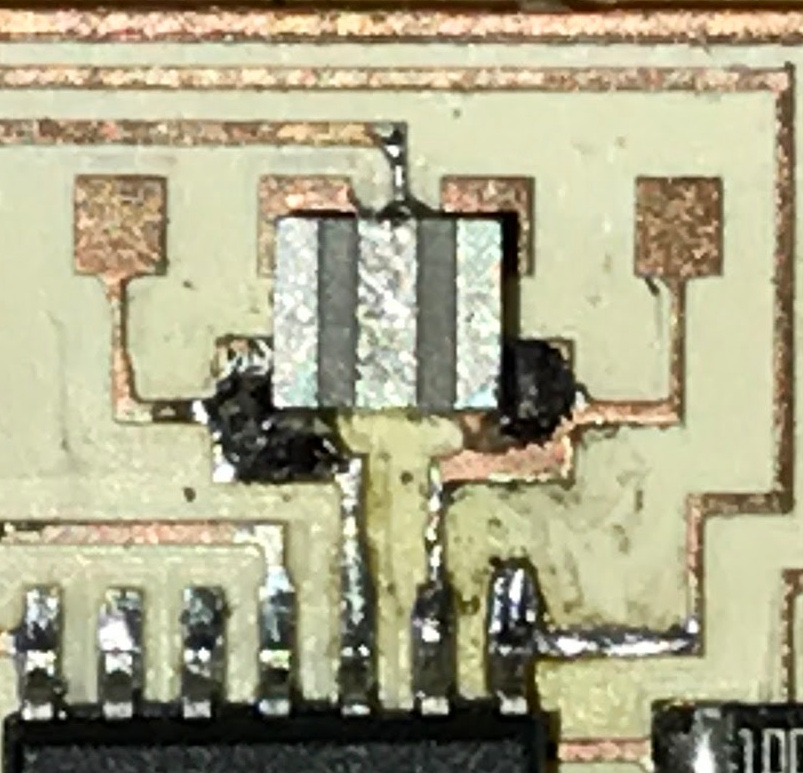
Close up of the resonator:
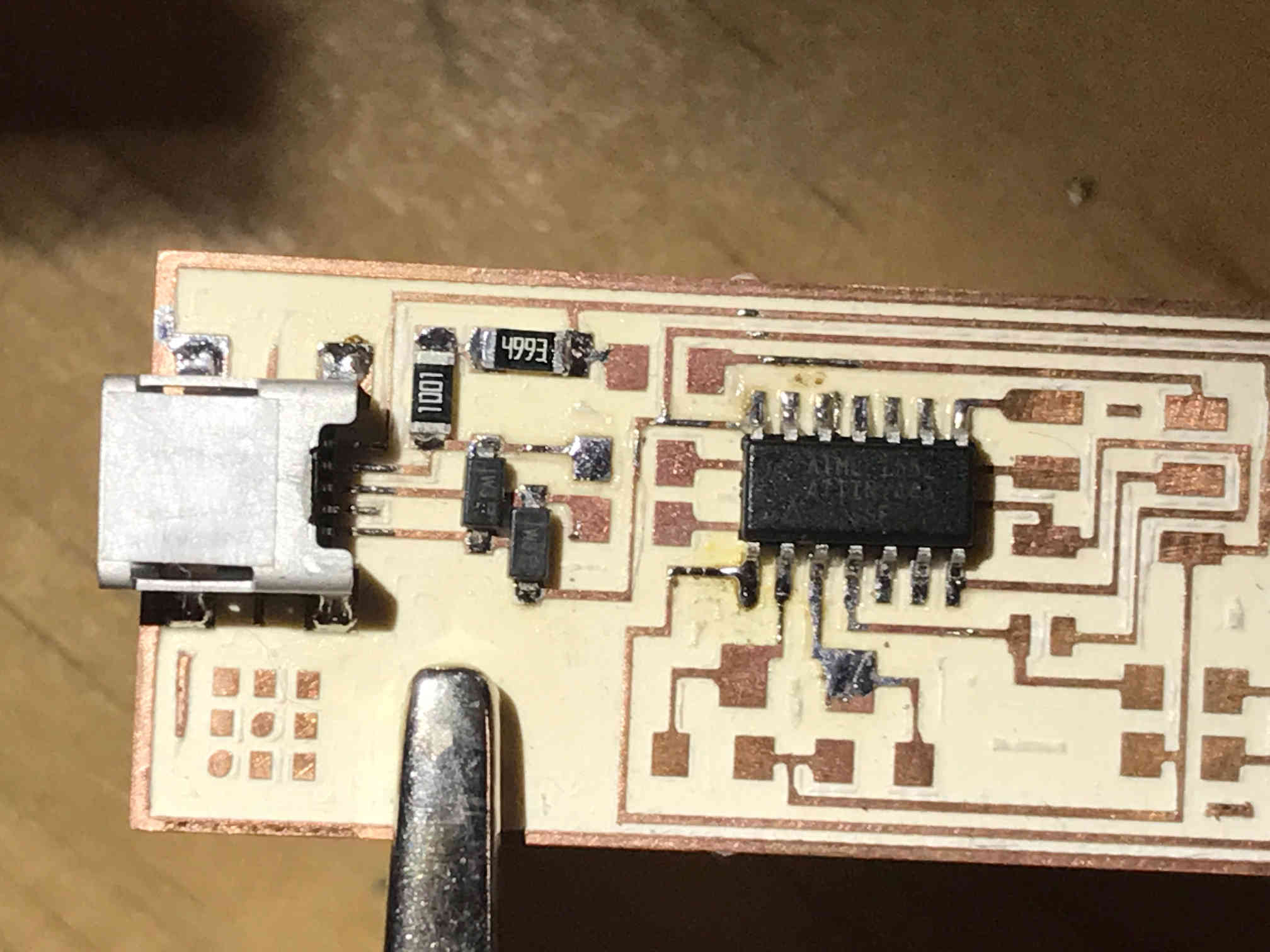
Detailed view of the soldered components:
When the ISP was ready, I connected it to the AVRISP, and the red led went on, meaning something was wrong with my board, so I disconnected and checked it again.
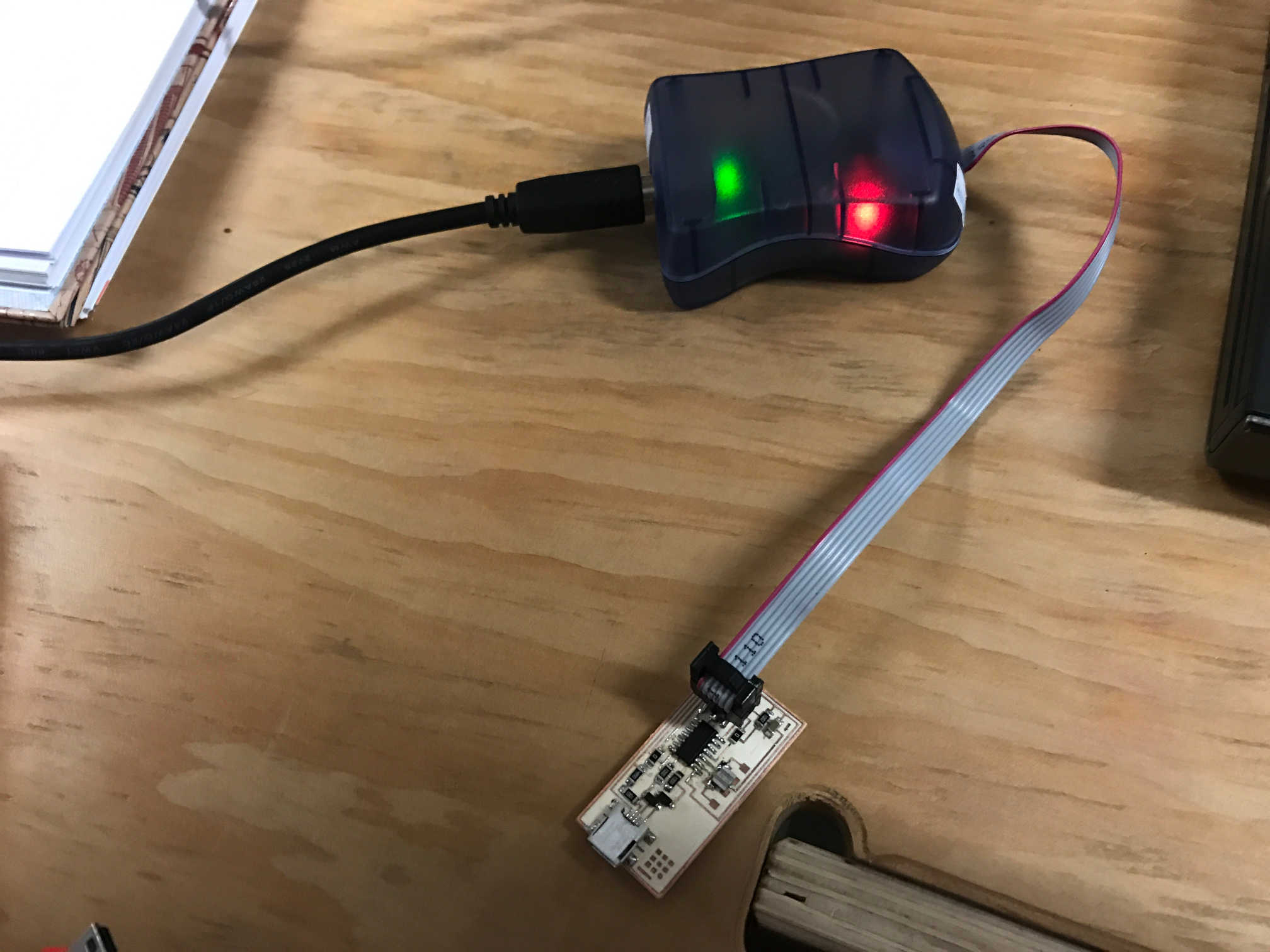
I found the error: I didn't connect one of the two 0 Ohm resistors. So I soldered it and tried again.
Programming the ISP
-
Installing drivers and libraries
I consulted this page for the proces of programming the ISP.
The following steps are commands entered on the ubuntu terminal. First, download and install the drivers and libraries for the AVRISP on the computer:
apt-get install flex byacc bison gcc libusb-dev avrdudesudo apt-get install gcc-avrsudo apt-get install avr-libcsudo apt-get install libc6-dev -
Download the firmware
Go to the folder where you want to download the firmware. Use "cd [folder]" command to go there.
wget http://academy.cba.mit.edu/classes/embedded_programming/firmware.zipUnzip the firmware
unzip firmware.zipGo to the unziped folder. Use "cd [folder]" command to go there.
-
Program the ISP
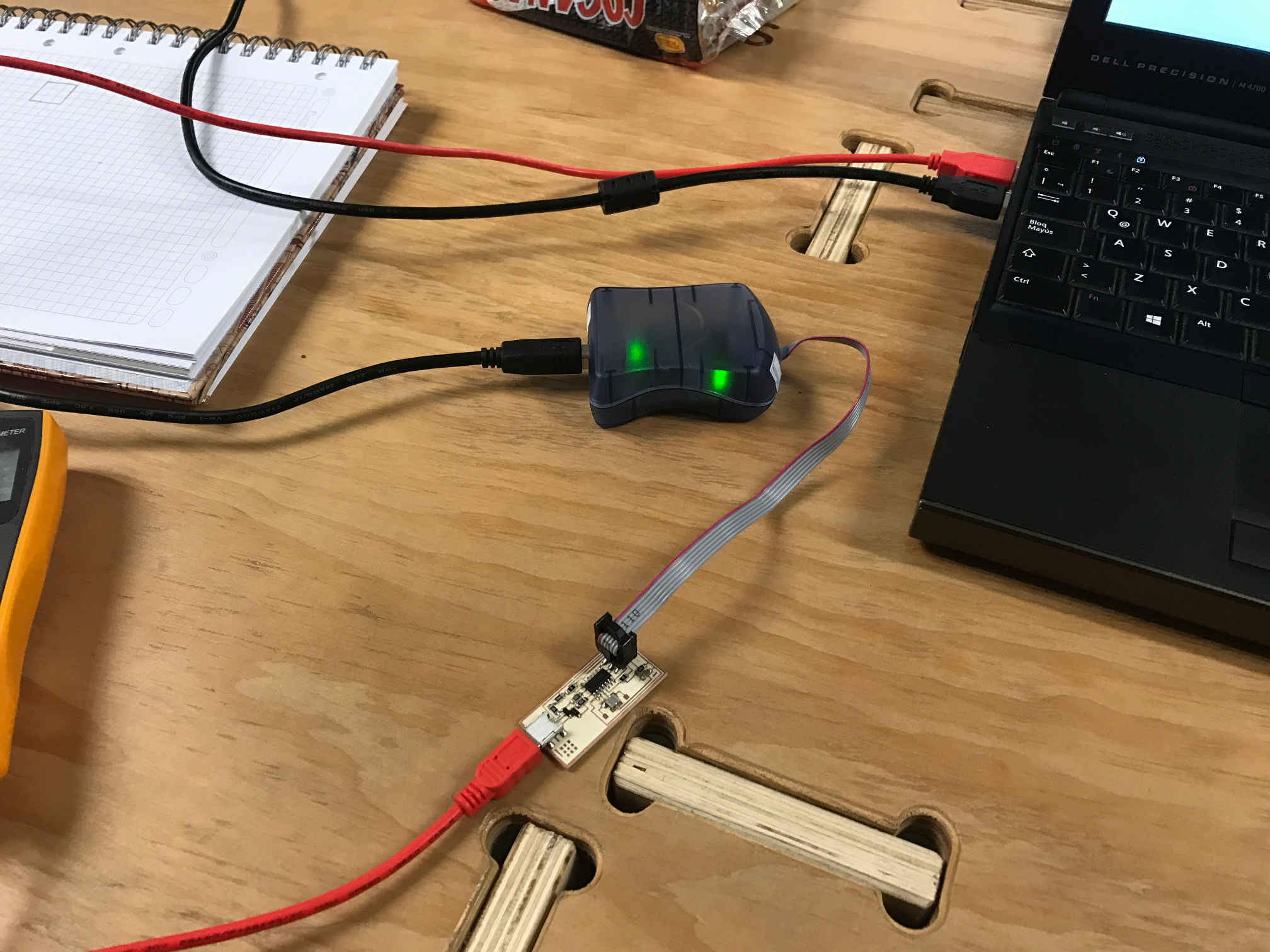
Now, make sure the AVRISP is conected to the computer and to the programmer, and also that the programmer usb port is connected to the pc (for power).
Continue on the terminal, press enter after each command. Read the output of each command to make sure it executed usccesfully:
make cleanmake hexmake fusemake programIf everything went well, list the usb devices and look for the USBtiny, that means the ISP was programmed correctly and the computer recognizes it.
lsusbIf you are sure the programming is done, remove the 0 Ohm resistor and test the ISP by programming a board.
Testing the ISP
-
The board is now a programmer for other microcontrollers, so, the best way to test it is by programming another board.
There is a board in the lab with a ATtiny45 microcontroller, so I used the Arduino IDE to write a blink program. Then made the connections on a breadboard, and used an arduino to power the board (only the VCC and GND pins from the Arduino are used).
On the arduino IDE, some changes must be done to use the new ISP programmer. First, go to File - preferences and add this address to the additional boards manager URLs:
https://raw.githubusercontent.com/damellis/attiny/ide-1.6.x-boards-manager/package_damellis_attiny_index.json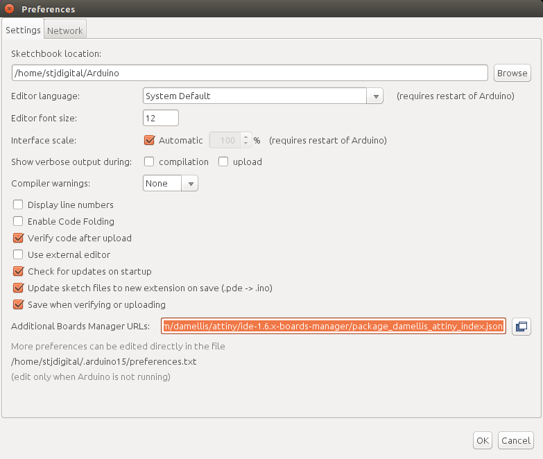
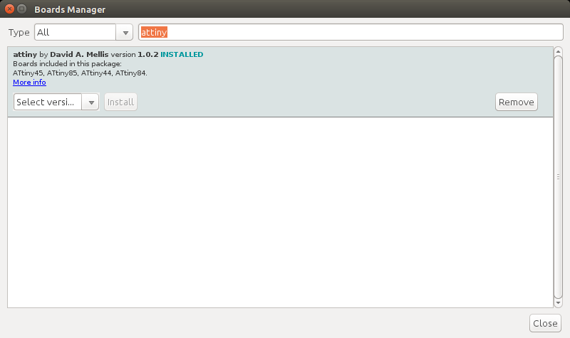
Then, go to Tools - boards - boards manager and search for "attiny" and install the package:
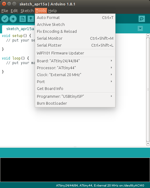
And now, choose the correct programmer, board, processor and clock on the tools menu of Arduino IDE:
Make the necessary connections for the blink circuit. Check the microcontroller pinout diagram for this:
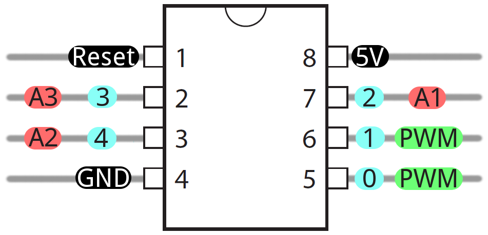
I used pin 0 for the led, so the blink program is:
void setup()Then, I sent the program to the board and it worked as expected.
{
pinMode(0, OUTPUT);
}
void loop()
{
digitalWrite(0, HIGH);
delay(100);
digitalWrite(0, LOW);
delay(100);
}This is the FabISP:
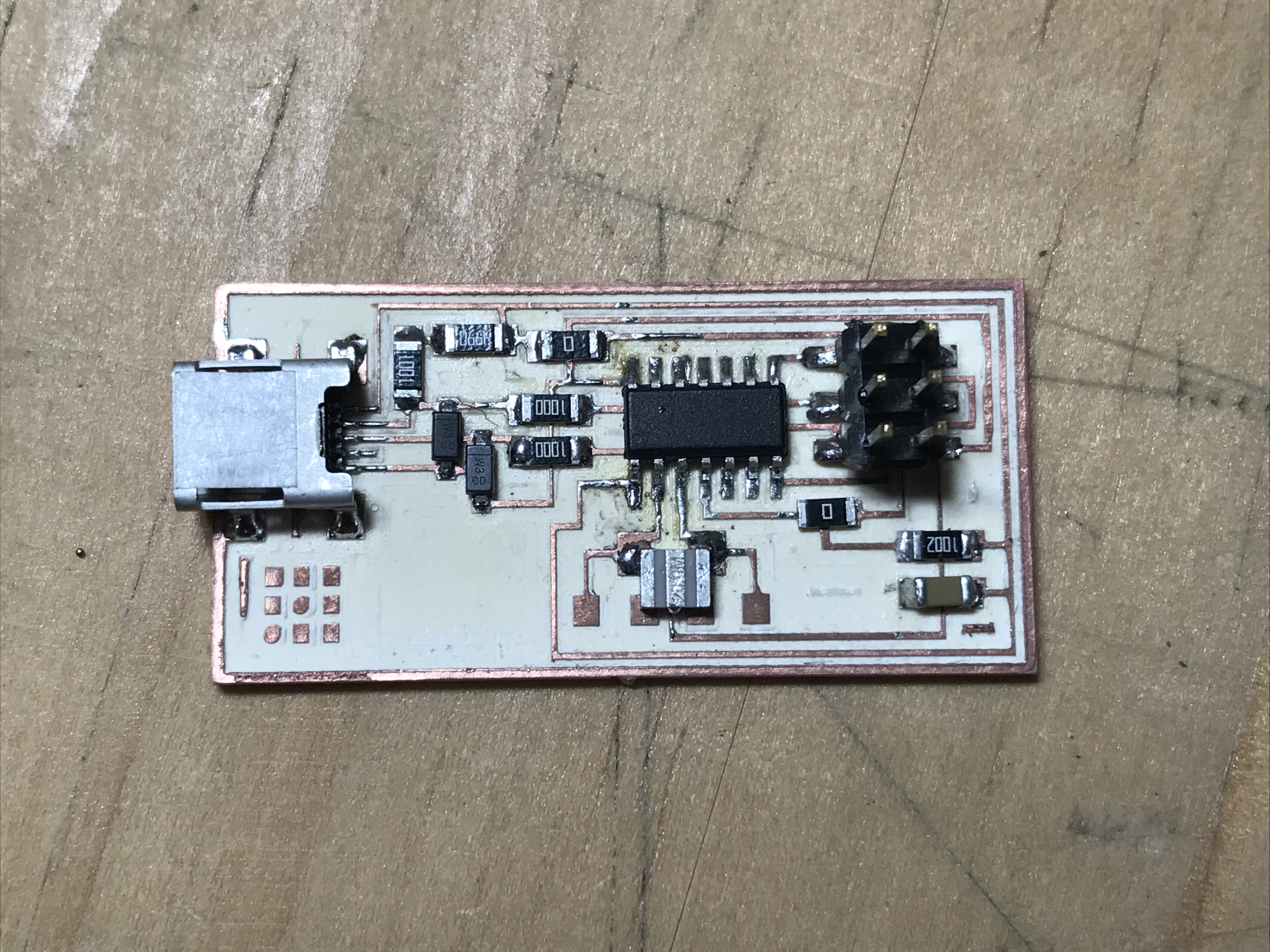
Back