Microcontroller Data sheet:
During this time I have learned a lot in practice, but it is always essential to link it with theory, to know the essence of what we are doing, so in this space I will share what I understood the Data sheet, I am not an expert , But it is important that we understand the following together:
For these activities the microcontrollers Attiny 44, Attiny 45 and Atmega328P
What are we talking about? What is a microcontroller?
A microcontroller is a programmable integrated circuit, capable of executing commands recorded in its memory. It is composed of several functional blocks, which fulfill a specific task. A microcontroller includes in its interior the three main functional units of a computer: central processing unit, memory and I / O (input/output) peripherals.
Midori, and what is the difference between these microcontrollers?
Okay, I'll explain you:
ATtiny:
Is a small microcontrollers with 0.5 to 8 kB of programmable flash memory, encapsulated 6 to 20 pins and a limited set of peripherals.ATmega:
Is a large microcontrollers with 4 to 256 kB of programmable flash memory, encapsulated from 28 to 100 pins, extended instruction set (multiplication and routing of larger programs) and wide set of peripherals.I'm showing you this picture just for find the differents between them.
Now let's go into the most relevant detail.
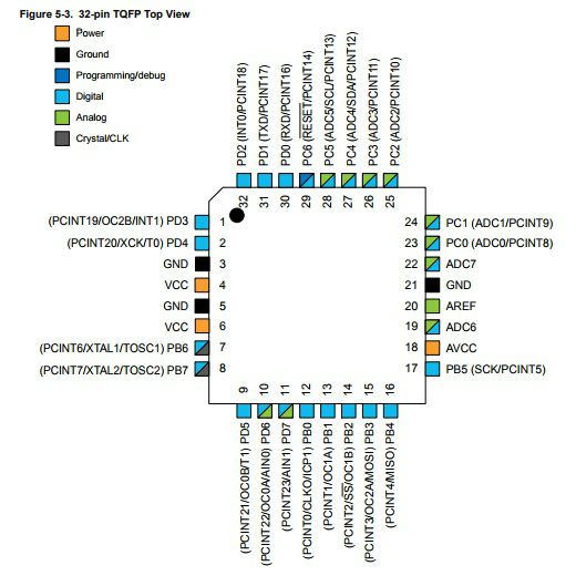
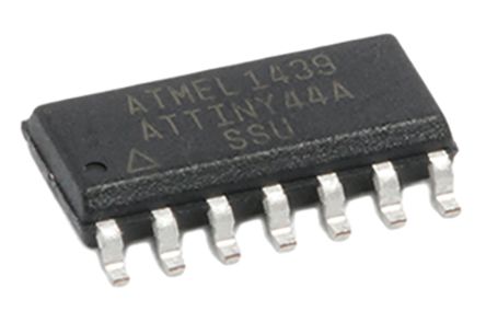
High performance, low power AVR® 8-bit microcontroller
4K byte of in-system programmable program memory flash (Atmel® ATtiny44.
Two Timer/Counters, 8- and 16-bit counters with two PWM channels on both.
10-bit ADC
14-pin SOIC, twelve programmable I/O lines
Operating voltage: 2.7 - 5.5 VDC
Speed grade: 0 - 8MHz at 2.7 - 5.5VDC, 0 - 16MHz at 4.5 - 5.5VDC
A low level on reset input for longer than the minimum pulse length will generate a reset, even if the clock is not running.
So, we can say that this microcontroller has 8-pin for the port A and 4-pin to the port B. Alimentation of 5vDC, ground and pin to reset.
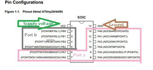
The pins of the ports A and B are of digital input and output, in the port A we have converters analog/digital and also they can be used as analog pins.
High performance, low power AVR® 8-bit microcontroller
2/4/8K Bytes of In-System Programmable Program Memory Flash
8-bit Timer/Counter with prescaler and two PWM channels
8-bit HIGH SPEED Timer/Counter with separate prescaler
-2 High Frequency PWM Outputs with Separate Output Compare Registers
- Programmable Dead Time Generator
10-bit ADC
-4 single ended channels / 2 differential ADC channel pairs with Programmable Gain (1x, 20x)
8-pin SOIC
Operating voltage: 2.7 - 5.5 VDC for ATtiny45
Speed grade: 0 – 10 MHz @ 2.7 - 5.5VDC, 0 - 20 MHz @ 4.5 - 5.5VDC
A low level on reset input for longer than the minimum pulse length will generate a reset, even if the clock is not running.
So, we can say that this microcontroller has 6 programmable I/O lines. Alimentation of 5vDC, ground and pin to reset.
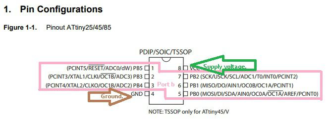
The pins of the port B are bi-directional I/O with internal pull-up resistors (selected for each bit).
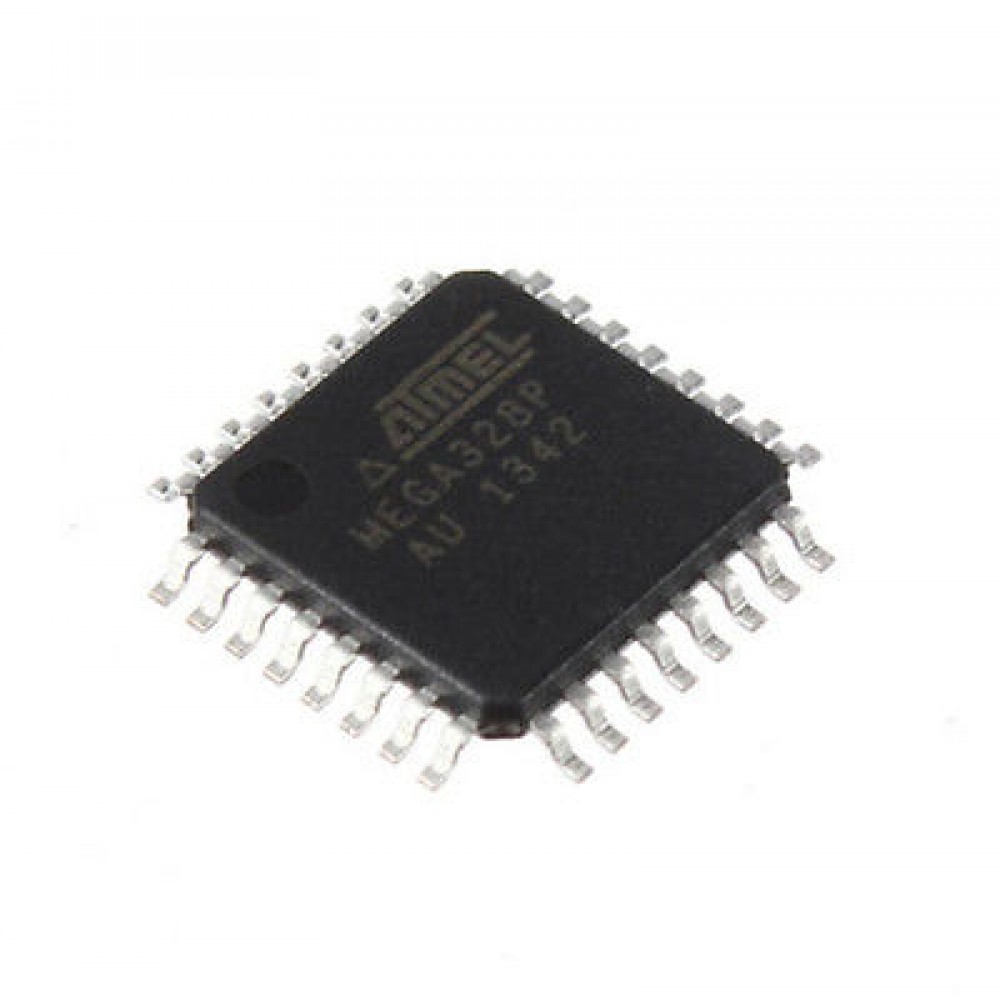
High performance, low power AVR® 8-bit microcontroller Family
131 Powerful instructions
32KBytes of In-System Self-Programmable flash program memory
1KBytes EEPROM
2KBytes Internal SRAM
Two 8-bit Timer/Counters with separate prescaler and compare mode
One 16-bit Timer/Counter with separate prescaler, compare mode and capture mode
Real time counter with separate oscillator
Six PWM channels
8-channel 10-bit ADC in TQFP and QFN/MLF package
6-channel 10-bit ADC in PDIP package
Two master/slave SPI serial interface
One Programmable Serial USART
One Byte-oriented 2-wire Serial interface (Philips I2C compatible)
23 programmable I/O lines
28-pin PDIP, 32-lead TQFP, 28-pad QFN/MLF and 32-pad QFN/MLF
Operating voltage: 1.8 - 5.5VDC
Speed grade: 0-4MHz at 1.8 - 5.5VDC, 0-10MHz at 2.7 - 5.5VDC, 0-20MHz at 4.5 - 5.5VDC
So, we can say that this microcontroller have 3 Ports, Digital supply voltage, supply voltage pin for the A/D Converter, analog reference pin for the A/D Converter, ground and pin to reset.