Add an output device to a microcontroller board you've designed and program it to do something.
Learning outcomes:
*Demonstrate workflows used in circuit board design and fabrication.
*Implement and interpret programming protocols
Have you:
*Described your design and fabrication process using words/images/screenshots.
*Explained the programming process/es you used and how the microcontroller datasheet helped you.
*Outlined problems and how you fixed them.
*Included original design files and code.
I had to add an output device to a microcontroller board that I'd designed and program it to do something. For this challenge I chose a Led Array.
First step
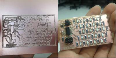
I chose to work with the hello.array.44.cad card. In the Fab Academy files, the designs can be found. I customized it using the "Eagle" software and later I performed all the procedure for its construction, first milling the card using the Roland Modela 20X machine and then soldered the components that are needed.
Here you have the list:
J1 ISP
J2 power
IC1 t 44
IC2 5V
C1 1 uF
R1 10k
5 - R499
20 - R0
20 led (I chose green leds)
Second step
To program the board, I downloaded the "C" and their respective "makefiles".
I used the first board that I made with Attiny 44 microcontroller on the week 4, my Fab ISPto program the Led Array board" on Ubuntu.
For that I previously downloaded the files. Here I will explain you how I did it.
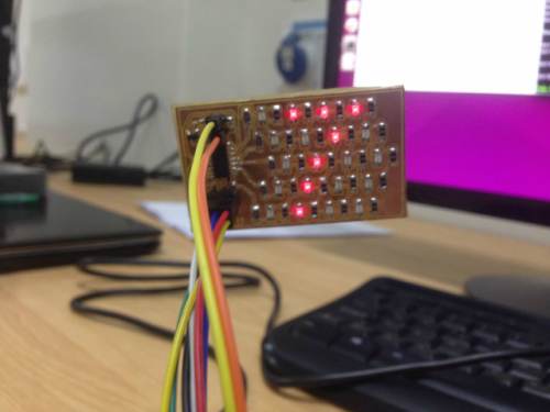
After understanding the logic of the programming of the board, I started to play, sending different orders. Here you can see the result.
After understanding the logic of the programming of the board, I started to play, sending different orders. Here you can see the result.
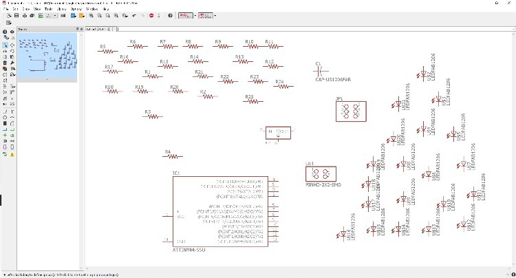
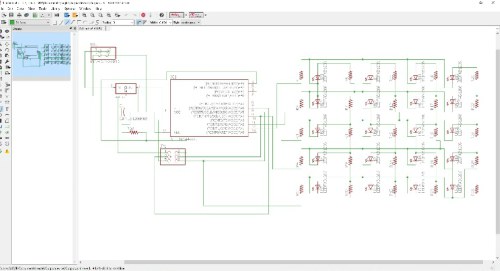
Redrawing my Output device board:
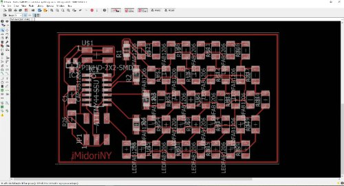
I opened Eagle software and selected all the components that I needed from the fab library :>
Here you have the list:
JP1
PINHD-2x2-SMD
ATTINY44-SSU
IC2
CAP-US1206FAB
R 1-26
LEDFAB1206 1-20
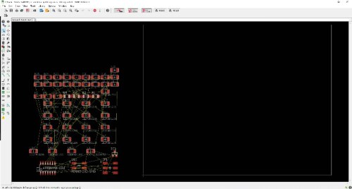
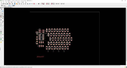
Designing process:
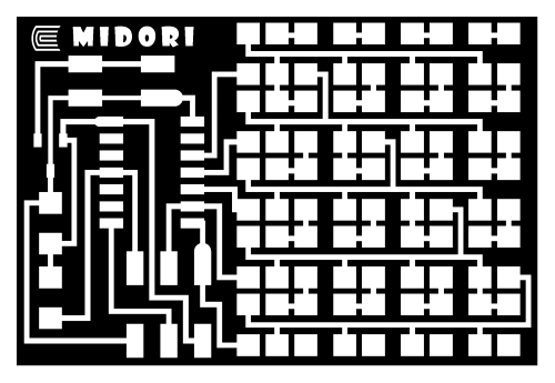
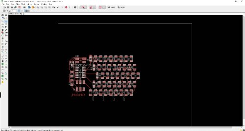
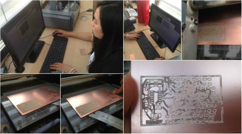
After creating the schematic, I created the board file of my "MidoriArrayboard". First I ordered the components and it was as you can see in the second picture (upper right side). For me it was fun to order each component and understand the logic of the matrix, but this Card really was big, half 10 cm wide, too much!. Then I had to redesign the redesign, based on the modification I wanted to make, change the led lines by led curves. And finally I managed to sort them as you can see in the pictures and exported the .png file.
Fabrication process:
Milling with the Roland Modela 20X machine
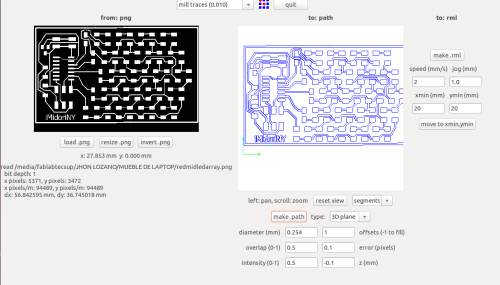
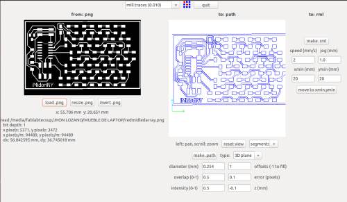
I selected "mill traces (0.010)" to work with the milling tool of 1/64, loaded the .png file and make path
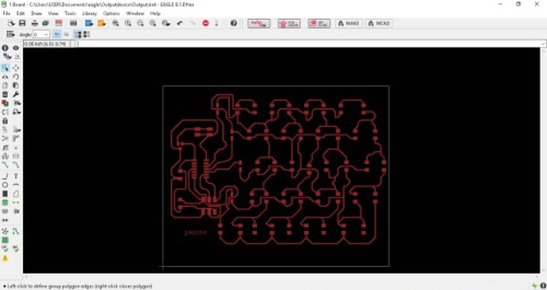
Here I found some problems with my desing and I had to verify the board file, because there was some joined paths
Here you can see the improved design in segments view:
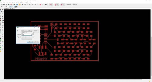
Then verify the parameters:
diameter (mm) 0.254
overlap (0-1) 0.5
intensity (0-1) 0.5
offsets (-1 to fill) 1
error (pixels) 0.1
z (mm) -0.1
speed (mm/s) 2
jog (mm) 1.0
xmin (mm) 7 y min(mm) [Those depends of where you set the board]
And "make.rml"
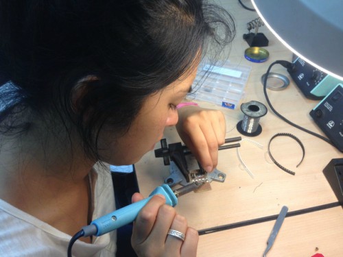
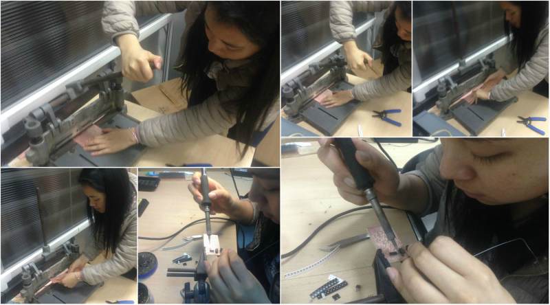
Then I cut with the guillotine and started soldering (At this point of the Fab Academy I can say that I really like to do it, I had not done it before Fab Academy, but I'm good at this. Until this moment I have not failed any board).
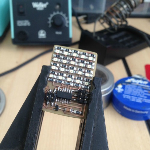
Here you can see how it looks:
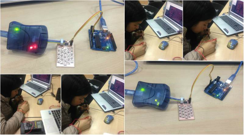
Now I will check if the work done works, using the AVR and Arduino as Power Supply.
As you can see in the photo, on the first attempt I threw red light, which indicates that there is a short circuit(never before had this happened to me). Relax! everything has a solution, I took the multimeter and began to explore where the short circuit was, to see how to solve it. Effectively, I found it, it was the corner of one of the paths that was colliding with another, using the cutter delicately, I managed to remove the tin from that corner. Finally, I tried again and flipped the green light, which means that there is not any short circuit and everything is ok.
Programming process:
Okay, to start programming first, we will remember what we learned from the Data sheet in the week 8.
How datasheet helps me :
Using this I made the connections correctly in the eagle software.
In case of some correction needed, using datasheet you are able to verify.
In order to program this board is vitally important to use the datasheet that gives you the exact location and name of each pin. Then you are able to make the connections to the output device.
Knowing this, we proceed to program. First you should download the files as explained above, but let's remember, inside the files of the Fab Acadamy, we go to week 10 and look for Led Array, download the file .C and .make, we save both in one Single folder and place it on the desktop. Now open in Ubuntu, the terminal and start typing the following:
* Enter the command: "cd eescritorio" to place the files that are located on the desktop.
* Then the “makelife” file is used and this prompts the file to generate another file called hello.array.44.hex which is used to program the ATtiny44 with the following command:
- sudo make -f hello.array.44.make program- avrisp2 (if you use the AVR)
- sudo make -f hello.array.44.make program-usbtiny (if you use the ISP)
Oops !!! There seems to be a problem, you can not program the card. Again, we breathe, everything has a solution, I picked up the multimeter again and checked pin by pin and found another union not allowed, in this case I had to heat the plate and tap it to drop the components on that side and re-solder after Remove the tin from that corner.
Ready!!!! Let's try it again:
Ok, now that it works let's change Neil's code, here are the attached, I hope you can try it and create many codes with this dynamic card.
Neil's Code:
//
//
// hello.array.44.c
//
// Charlieplex LED array hello-world
//
// Neil Gershenfeld
// 11/13/10
//
// (c) Massachusetts Institute of Technology 2010
// This work may be reproduced, modified, distributed,
// performed, and displayed for any purpose. Copyright is
// retained and must be preserved. The work is provided
// as is; no warranty is provided, and users accept all
// liability.
//
#include
#include
#define output(directions,pin) (directions |= pin) // set port direction for output
#define input(directions,pin) (directions &= (~pin)) // set port direction for input
#define set(port,pin) (port |= pin) // set port pin
#define clear(port,pin) (port &= (~pin)) // clear port pin
#define pin_test(pins,pin) (pins & pin) // test for port pin
#define bit_test(byte,bit) (byte & (1 << bit)) // test for bit set
#define led_delay() _delay_ms(1) // LED delay
#define led_port PORTA
#define led_direction DDRA
#define A (1 << PA1) // row 1
#define B (1 << PA2) // row 2
#define C (1 << PA3) // row 3
#define D (1 << PA4) // row 4
#define E (1 << PA5) // row 5
void flash(uint8_t from, uint8_t to, uint8_t delay) {
To define the directions of your led Array board, you have to edit the secuence ( comand flash)
To define the light set with the led, in the #define command, it locates according to the row. This allows you to define which is the logic of the movement and later where it is declared flash, can be combined according to what you have declared.(For example, go back to see that part of the code and all the A exchange it for D) It is super dynamic!!!!, I made the initial of my name, here I show you the video and I leave you the code of the part that I changed.
Another thing I also learned is the following:
led_cycle(1,100)
The first number represents the quantity of cycles and the last the time between leds.
In this case that is read as: 100 cycles in 1ms
Another important thing is that if you want that you do not catch a led you place in the front part //
Here I left my own code, enjoy it and try to do it
Through this experience, I learned to add an output device and control the functions that I want it to perform. It was a fun process to work with the hello.array.44.cad card and it required a lot of logic.
Self Evaluation:
I achieved to add an output device ("Led Array" and "MimiLed Array") to a microcontroller board that I made (Fab ISP).
I demostrated workflows used in circuit board design and fabrication. At this point I can say that I can make boards with Eagle (desing and re- design) and I learned to use a Roland Modela 20X machine.
I implemented and interpreted programming protocols. I have not a background programming, but through those experiences I learned a lot. Now I understood how important is to know about data sheet, because it helps a lot when you are programming, you will be right writing the correct denomination of each pin.
Understandig data sheet allows you to desing and program in the correctly way.
I considered my problems in this assignment as opportunities to learn. For example when I had to re desing my board in Eagle, because the Roland Modela software show me joined paths. From this experience, the next time I will consider it to do it better.
I learned how to solve problems when a short circuit appears.
I loved this activity because it allowed me to learn a lot, really. This is a very interesting circuit since it teaches us the principle of how to make panels in the future, now that I was able to redesign my card, calling it "Midori Array" and give it a curved shape, I can think of many more ideas that will eventually Developing, how to create a panel with the logo of my university (I will have to add several leds) and that the matrix of leds will have a craziest programming. I will do it!


.jpg)
.jpg)
.jpg)
.jpg)
.jpg)
.jpg)