I had to make something big for this week so I decided to start making the base of "SmartBeddo", my final project.
In order to achieve this challenge, I downloaded and used Rhinoceros 5 for the design and the Shopbot for fabricated.
Make something big (on a CNC machine).
*Document the process of design and production to demonstrate correct workflows and identify areas for improvement if needed.
*Explained how you made your files for machining (2D or 3D).
*Shown how you made something BIG (setting up the machine, using fixings, testing joints, adjusting feeds and speeds, depth of cut etc).
*Described problems and how you fixed them.
*Included your design files and ‘hero shot’ photos of final object.
I had to make something big for this week so I decided to start making the base of "SmartBeddo", my final project.
In order to achieve this challenge, I downloaded and used Rhinoceros 5 for the design and the Shopbot for fabricated.
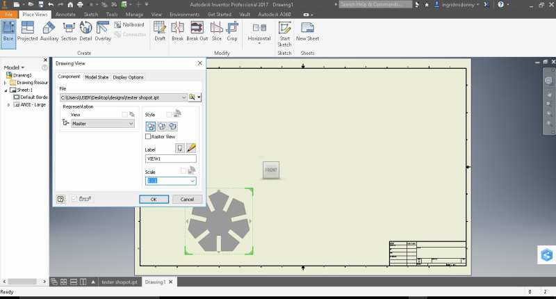
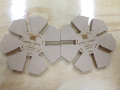
Hello! In order to complete this activity I have to design something that allows testing the joints of that material. In order to comply, I first chose to work with 12 mm MDF and designed this heptagono with variations of 0.5 mm, from 12.00 mm to 12.35 mm using Inventor software( design .stl )
Ok, once I exported the design to an inventor's plane, I got the job done, I saved the file in USB and I'm going to the Shopbot area.
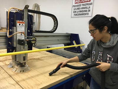
To begin with we are going to leave the work area clean, that is why I take the vacuum cleaner and start to sort a little around here.
.jpg)
.jpg)
Yes now! The work area looks great.
.jpg)
Ok, we removed the material that is over (thanks to my friend John for supporting me)
And place the MDF board 12 mm thick. Then secure again with the screws and we already have ready the working area in the Shop bot
We opened the software and started:
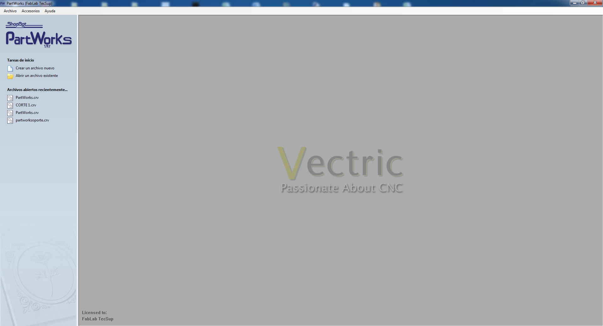
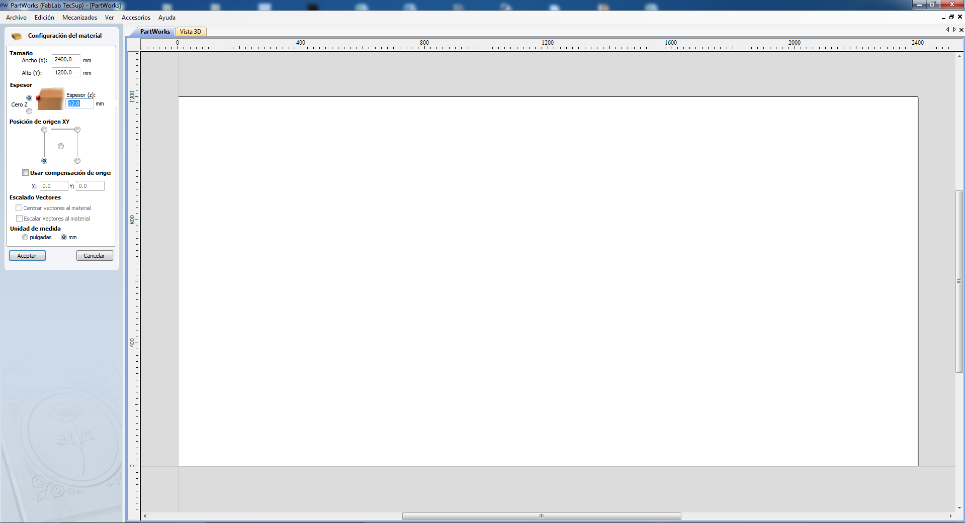
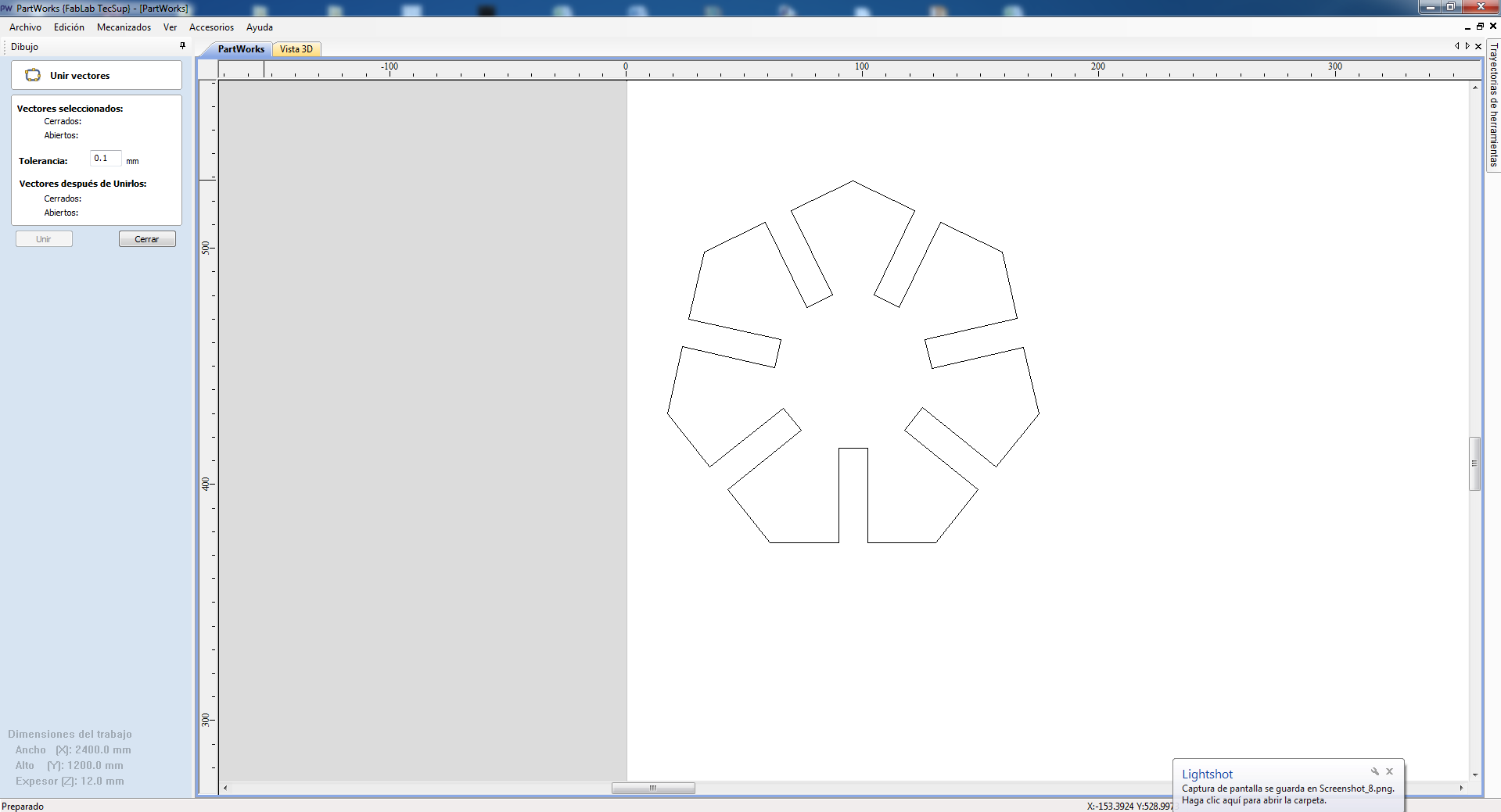
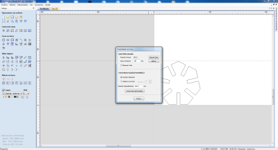
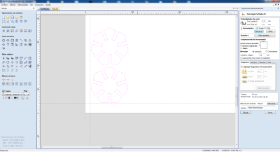
The software is called PartWorks, we open it and configure the data of the material that will work, in my case these were the data:
widht: 2400 mm
height: 1200 mm
thickness: 12.0 mm
Click on accept
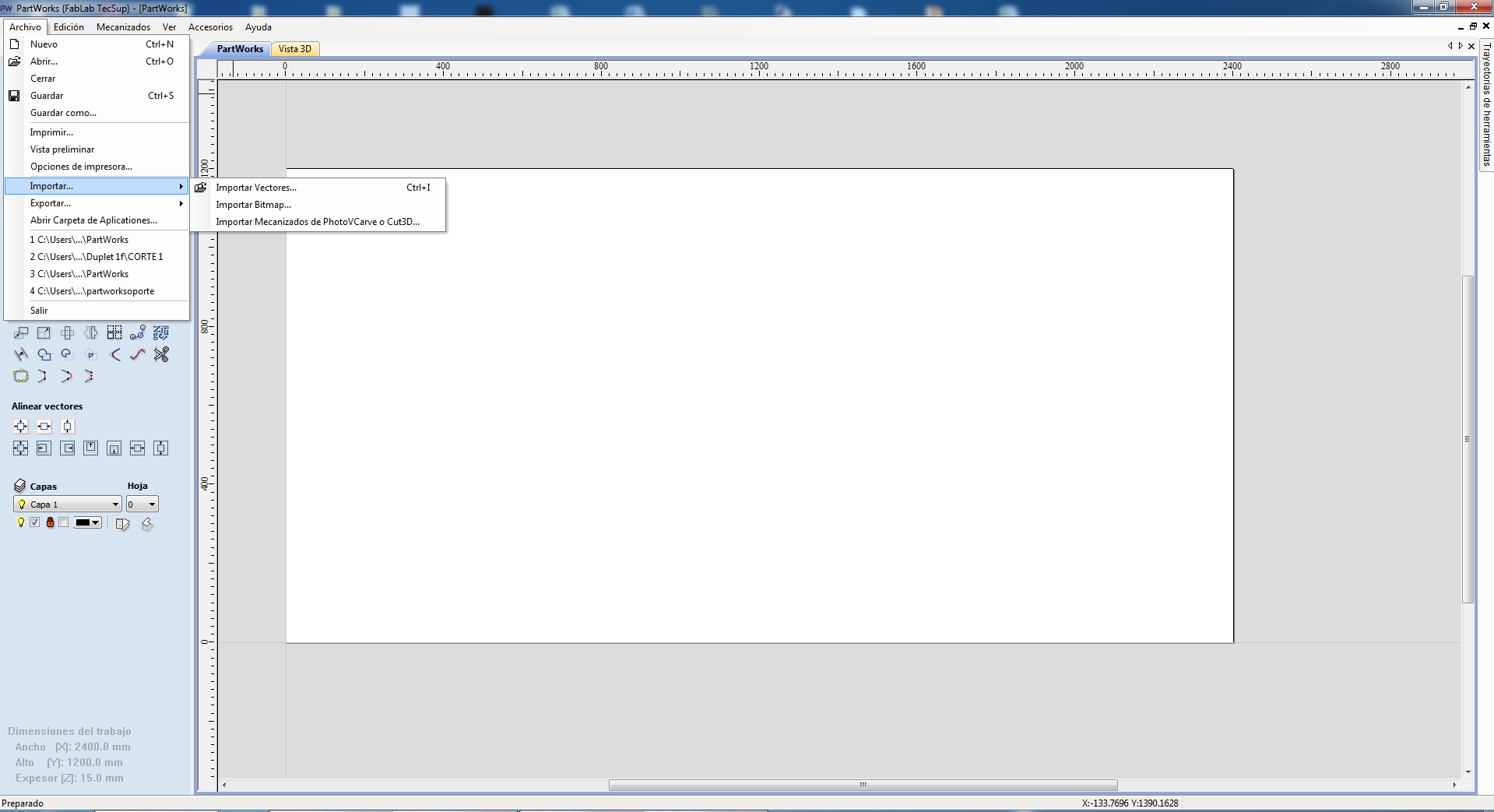
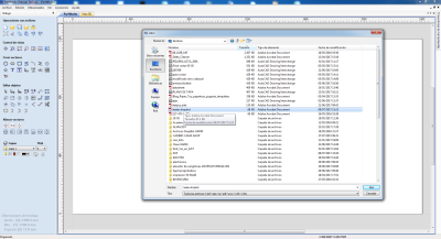
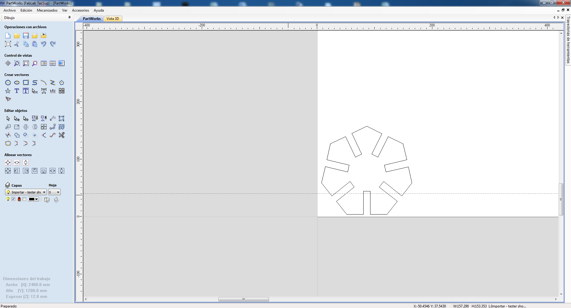
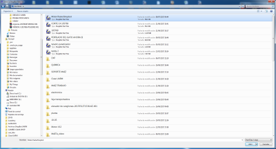
And choose to import the file that we have in .pdf format
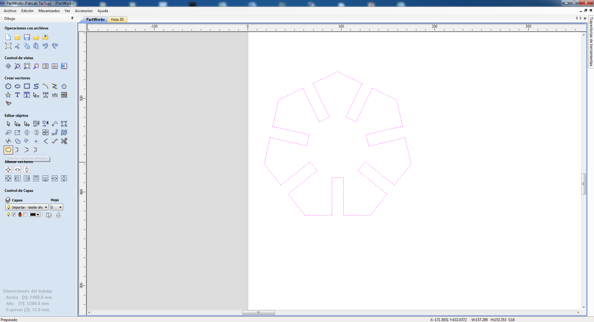
Then we join the vectors with the tool "union of vectors"
Type: Tolerance: 0.1 mm and click on "Join"
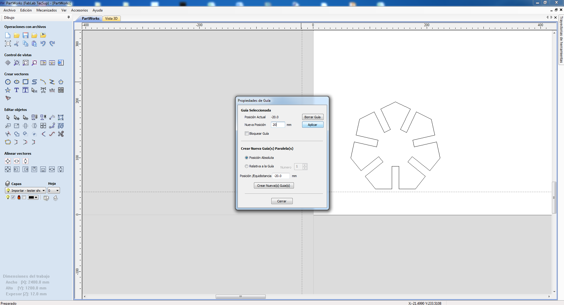
Now we place the design in the work area considering the guides: That's why we enter 40 mm as "new position" (in "x").
we enter 20 mm as "new position" (in "y").
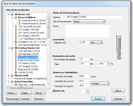
Then choose "create profile toolpath" in the tool database, "1/8 * Straight (13728)", because we will work with this milling cutter. And we also configure the options that appear, I will place a "chamfer head femur" 4mm. In the case of the "final cut depth: 14 mm (2 mm more than the material, to ensure that the whole cut is made. Finally we add a name to the path to save the project.

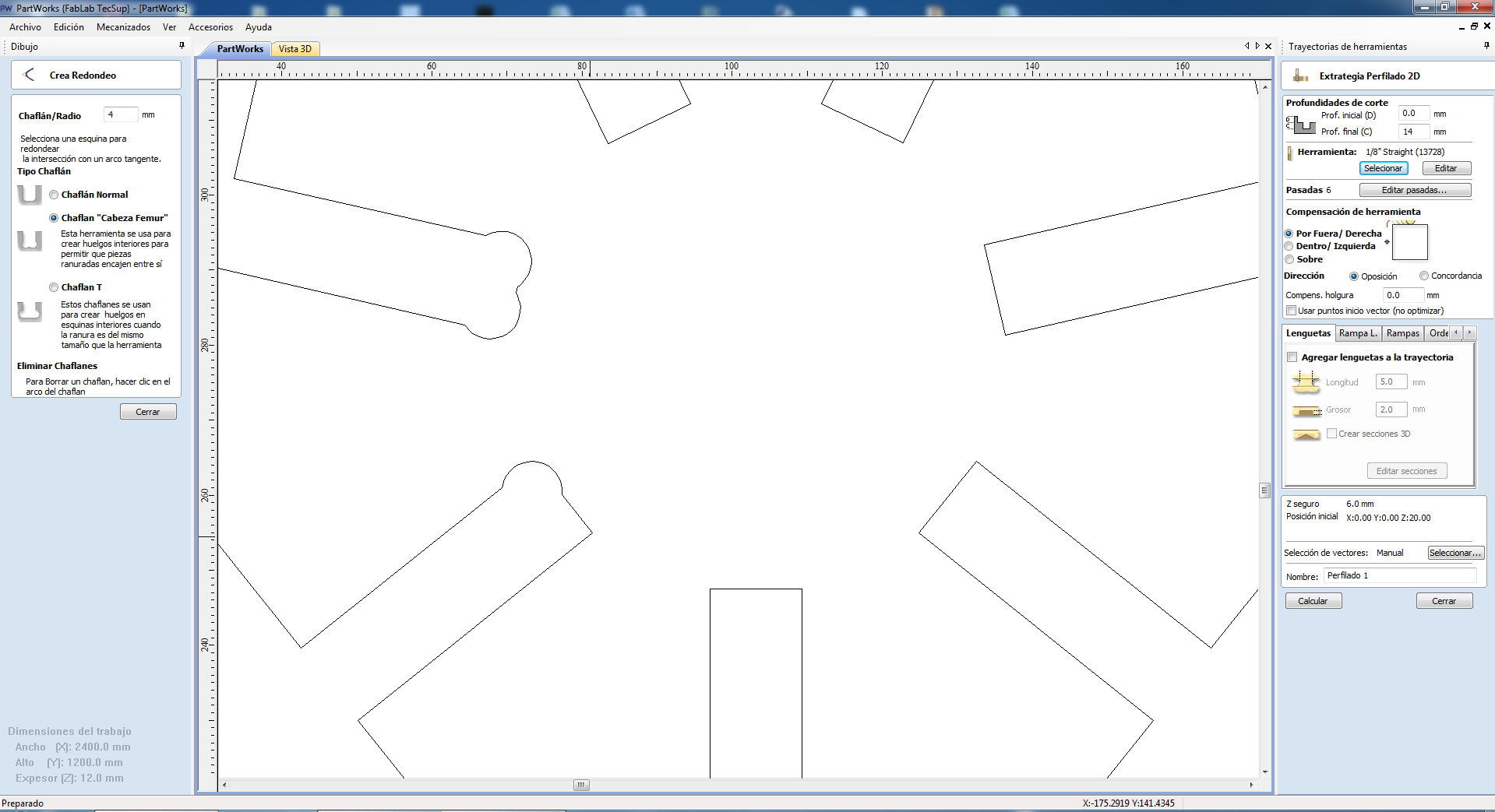
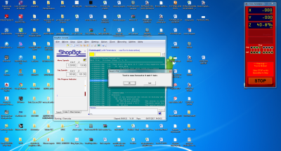
When you click on accept, we will get a warning for having put the depth greater than the thickness of the material, which means that the material will be cut, no problem, put "OK" and the path will be created:
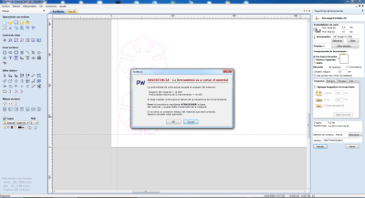
When you click on accept, we will get a warning for having put the depth greater than the thickness of the material, which means that the material will be cut, no problem, put "OK" and the path will be created:
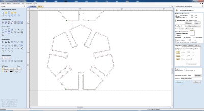
And we see that in the positioner the green light is activated.
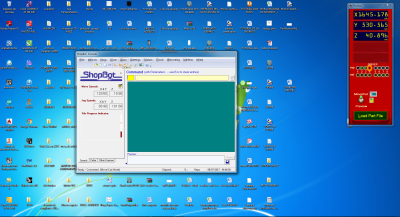
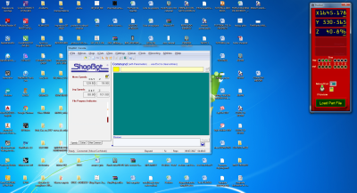
And we see that in the positioner the green light is activated, to start locating the machine head
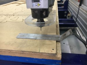
Another small window appears and we are located in "X and Y".
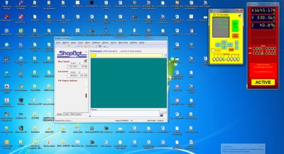
Then the plate is placed to calibrate "Z" and the document of the trajectory that we previously saved is loaded:
A new "Part file load" window will appear and click on START.
And the work begins.
Achieving :.
.jpg)
Then we sand it:
And it looks like this:
.jpg)
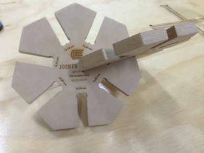
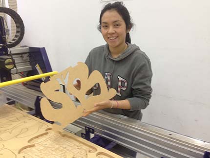
To recognize the different joints, I will use the Epilog Legend 36EXT machine, to rasterize the dimensions, first cut the silhouette in 3mm MDF and remained as a mold to be able to work the raster in the piece cut in the Shopbot:
.jpg)
Here is the result:
After tried each joint, I can define 0.35mm as the result of the test. So it is the tolerance parameter.
Summarizing, the parameters to work with 1/8* Straight, are these:
 >
>
cut speed (mm/s): 60
plunge speed (mm/s): 30
Plunging depth: 2.5
pass: 1.27*40%
spindle speed (RPM): 8000
file units: mm
Number of passes: 6
Allowance Offset of -0.35 mm
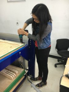
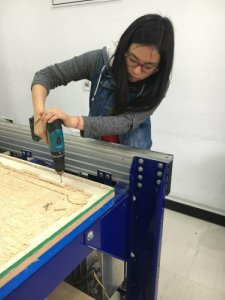
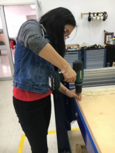
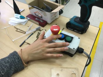
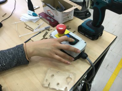
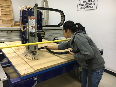
Most important, first, I will hold my hair, protect my eyes and ears.

First, I started designing how my base bed would look on a simple paper. Then I opened Rhinoceros and started designing there. I tried to make a modular base. Those were the steps:
1. In the front view, to start designing, I preferred to draw my idea using lines and curves.
2. Then I copied it and turned it to lines to use the command "Surface/sweep by two rails" and selected those lines as rails and then the other lines as what I wanted to sweep. Double enter.
3. Now, I had to select the "Contour" command, here it asked me in which view I wanted to make a contour and I had to select the face where I wanted and wrote what distance.
4. Then I copied that, deleted the surface and just kept the lines. I selected my lines and the "Surface extrusion" command.
5. I wrote the distance thinking about the thickness of the material that I would use. In this case I used MDF of 12 mm. If is the case, you have to make sure of the extrusion direction, verify before click.


6. So now I had the parts of my modular design. Now I had to send it to the shopbot software called "PartWorks" (pay attention here: you have to make a .pdf format).
7. Following the steps explained at the first part of this assignment, Let's start cutting! I used the same mill: 1/8
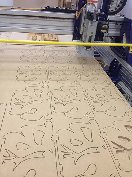
Here I had an inconvenience, when I was removing the pieces, the milling tool did not go through the material (MDF) and I had to use another tool to finish removing the pieces.
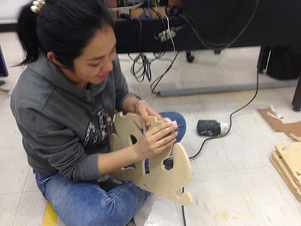
8. When I had all the pieces I started sanding all the edges for a better finish.
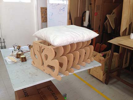
9. Finally I could build the SmartBeddo base without any problem.
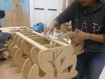
I enjoyed this experience, the Smartbeddo base is using as a puff here at Fab Lab.
The joints worked very well.
I used the Shopbot machine but I have to try more, with differents milling tool, to improve my skills
For this challenge I used Rhinoceros for the desing. For me was interesting to create something with an idea that I sketched. But you can try with another software, just remember to export the file in .pdf format.
In this case I had an inconvenience when removing the pieces, since the milling tool did not go through the material (MDF) and I had to use another tool to finish removing the pieces. Analyzing why this happened, I understood that it is important that the base of the work area should be adequate and in this case was worn and uneven. Because when I made the joints tester I had no problem.