
This week I redrew an echo hello world board and added, at last, a button and LED.
In order to achieve this challenge, I used "Eagle Design Software" for Windows PC, Fabmodule (ubuntu) and Roland MODELA CNC Milling machine.
Redraw the echo hello-world board, add (at least) a button and LED (with current-limiting resistor), check the design rules, make it (if you have time this week, test it).
optional: simulate its operation. Measure its operation
*Select and use software for circuit board design.
*Demonstrate workflows used in circuit board design.
*Shown your process using words/images/screenshots.
*Explained problems and how you fixed them, including how you worked with design rules for milling (DRC in EagleCad and KiCad).
*Included original design files (Eagle, KiCad, Inkscape, .cad - whatever).
This week I redrew an echo hello world board and added, at last, a button and LED.
In order to achieve this challenge, I used "Eagle Design Software" for Windows PC, Fabmodule (ubuntu) and Roland MODELA CNC Milling machine.
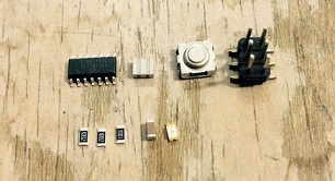
I downloaded and installed the fab.lbr of echo hello- world, then I opened a new project and started working, exporting the next list of components on the new schematic:
Unpolarized_Capacitor1206
ATTINY44-SSU
PINHD-2x3-SMD
FTDI_BASICPTH
R_US_M1206
R_US_M1206
R_US_M1206
6MM_SWITCH6MM_SWITCH
RESONATOR
LED1206
Then I made the relevant connections. I used pin 10 for the BUTTON and pin 6 for the LED.
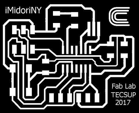
I generated the file.brd. For me this was the part that took the most time, because I had to make the circuits from scratch. After "N" attempts to find the best route and join the components, I achieved the following design.
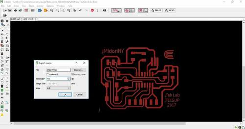
Then exported the file board on monochrome option and a resolution of 450 dpi, and then you have the result.
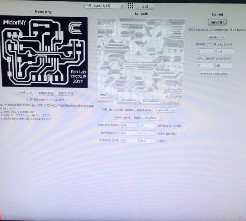
It was almost done, the next step was to open the GUI on the Fab Modules.
I selected the format and process that we would perform, in this case, PNG and Roland Modela MDX 20.
Click in make_png_rml.
Load the file PNG of board.
I selected the type of cutter that I will use (1/64).
Then regulated the parameters of milling.
diameter: 0.4 mm
overlap: 0.5
offsets (-1 to fill): -1
error: 0.1 pixels
intensity: 0.5
z: -0.1 mm
I clicked in make_path to generate the G code that will be the file with the trajectories of headstock.
I cleaned up the the copper board and put masking tape on the board in order to attach it in the iron of the Modela MDX20, then calibrated the A,Y and Z axis to get an optimal milling of the board.
Finally clicked on make.rml

After milling and welding the board, there you can see my result. I achieved this challenge!!!!!
Eagle is a practical software to design electric circuits.
For this challenge, you have to be creative to find an optimal route for the circuit.
I enjoyed this challenge.
DRC? What it is DRC?, relax! I will explain you.
Honestly I didn't use, but we are here to learn, so , thanks to Epifanio Cueva for the question and Jhon Lozano for the support. I will explain you how I used it.
Step by step, DRC means DESIGN RULE CHECK. This command checks a board against the current set of Design Rules.
Design rules: are those that define all the parameters that the board layout has to follow.
The Design Rule Check checks the board against these rules and reports any violations.
The errors found are displayed as error polygons in the respective layers, and can be browsed through with the ERRORS command.
Ok, stop talking, see this video.I made it for you, practice with me.
I learned to work with Eagle software, to design circuits board. I achieved to redraw the echo hello-world board, add a button and LED. Also I test it.
Optionally I measured is operation, as I showed you with the pictures and videos.
Through this experience I can say that if there is a problem in the design (either missing to join a few pins) you have to be creative and persevering.
It is important to use DRC command, to get better results.