Project Proposal Project Planning Project Documentation The Build Processes, Testing and Results Final Project Presentation
The Build Process
Click on this link to view my presentation slide, which gives an overview of the three stages of my laptop stand design and electronics circuitry customized design.
Laptop Stand Design
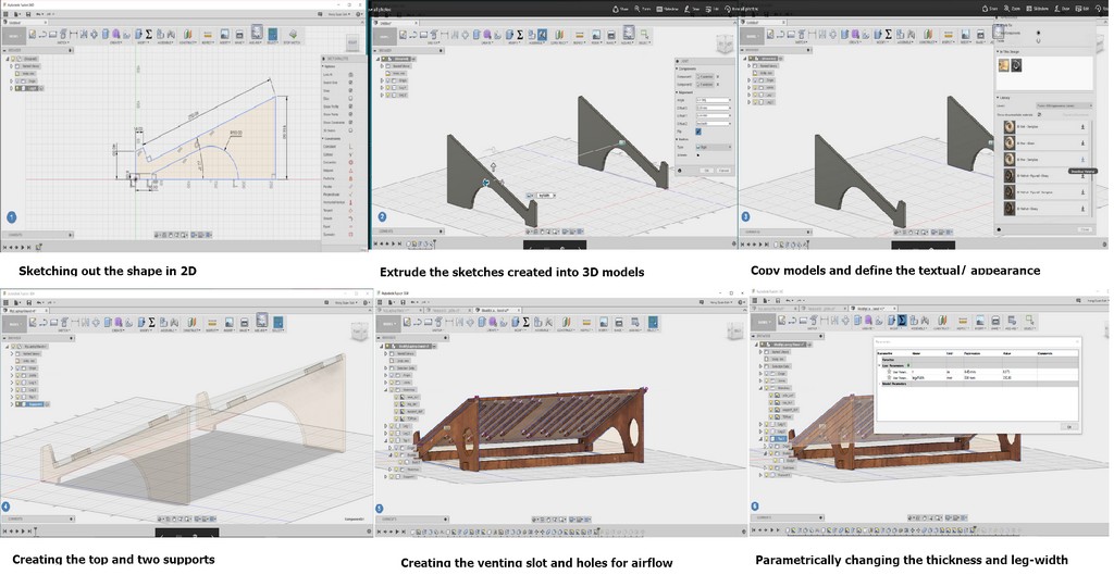
Lets flash back a little bit - Way back at the early stage of this course at 1st February 2017, I was inspired to build my laptop stand based on the knowledge gained from the following Fusion 360 video. Fusion 360 Tutorial (By Taylor Stein).
As an atempt to reduce the heating effect caused by close contact of my laptop stand with the computer table; I have added in numerous slots on the base of my incline laptop stand. My final design is shown:
Material choice for my laptop stand
I still remembered way back in week7 exercise where we learnt to produce something big using CNC router with plywood of half a inch thick plywood. During that time, I was wondering whether it is possible to produce something small like a laptop stand using the huge CNC router with those half a inch thick ply. After some consideration and look at the quality of the plywood, I had asked myself whether I required to use those ply of half a inch thick. As my laptop would probably weight about 2.5 kg.
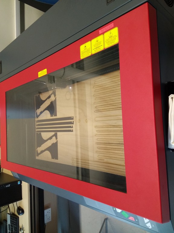
With that in mind, I proceeded to test out my design with ply of ~5mm thick using laser cutting:
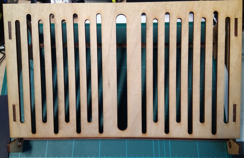
Valla! The laser cutting output of my laptop stand after assembled is as illustrated.
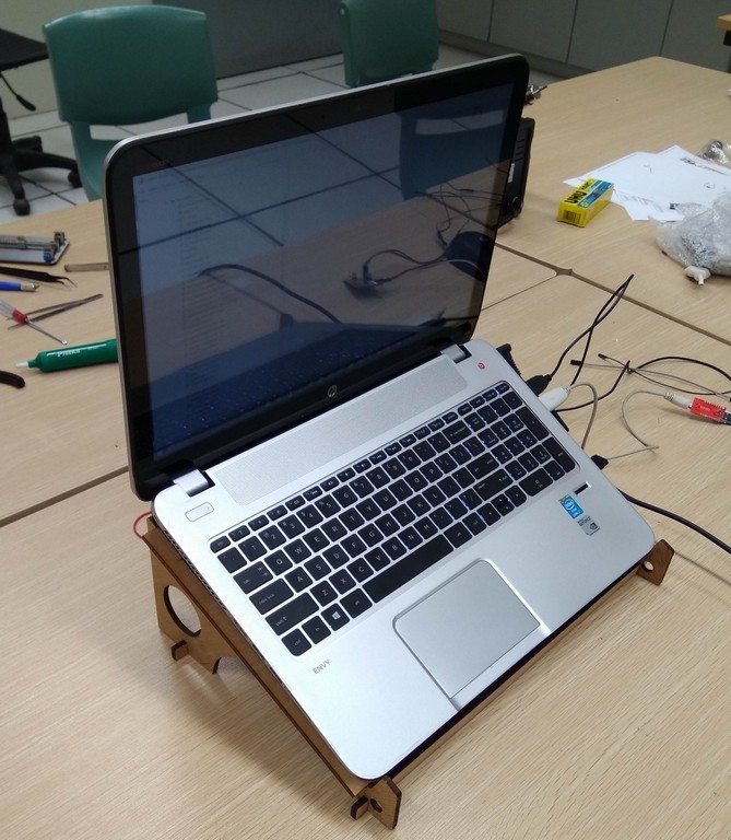
With the cut out, I then proceeded to test out by fitting my laptop on top of the inclince laptop stand as shown:
Electronics Design consideration
I want the circuit to be small and flexible with minimum break-out board to minimized the numbers of interconnecting cables. My immediate considertion was to use a ATtiny series of processor- as I remembered in one of the lecture Prof. Neil mentioned about the flexibility of using these MCU. On the same time, I also have considered the possibility of using original Fabkit04 that came with a ATmega328P MCU on board as my controller MCU. Without rerouting of the board file, this option will definitely have some break-out board if I will to include my thermistor temperature sensing circuit.
As I could not decide what was the best option, so I ended up building a Fabkit 4.0 with ATmega 328P as well as my final ATtiny85 controller board. During the test testing phrase, my fabkit4.0 board could not run the example blink programme correctly. So I decided to move on and focus on using my ATtiny 85 MCU controller board and scale down my project to just doing the temperature sensing and manual control of lamp on-off circuit.
Design of ATtiny Controller Circuit Board
Designing of the board in Eagle.
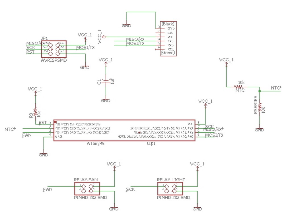
Final Design of my controller board layout
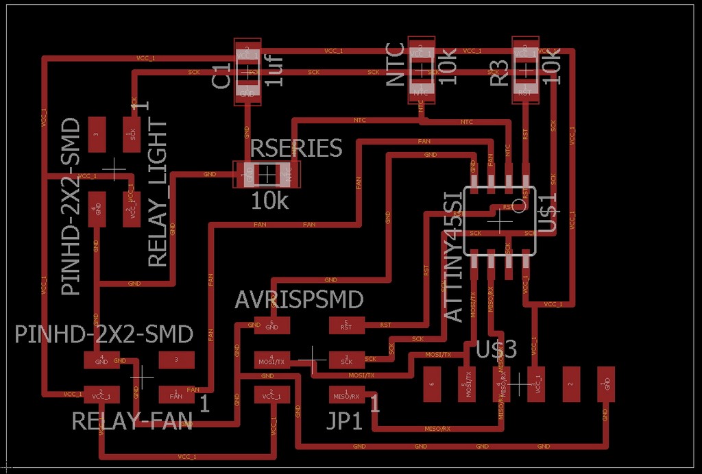
The pcb after stuff in all the components

Circuitry Housing
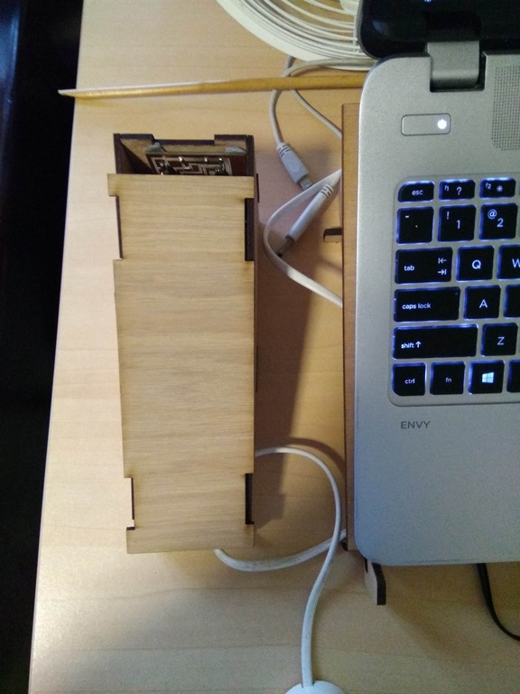
I designed and made a housing for the circuitry to hide the unsightly wires using computer control cutting process; with laser cutting on ply. The challenge that I foresee was my on board thermistor might not be able to sense the hot air blowing out from my laptop; if it is being house in a totally enclose housing. Otherwise the thermistor circuitry would need to be separated from the main controller board.
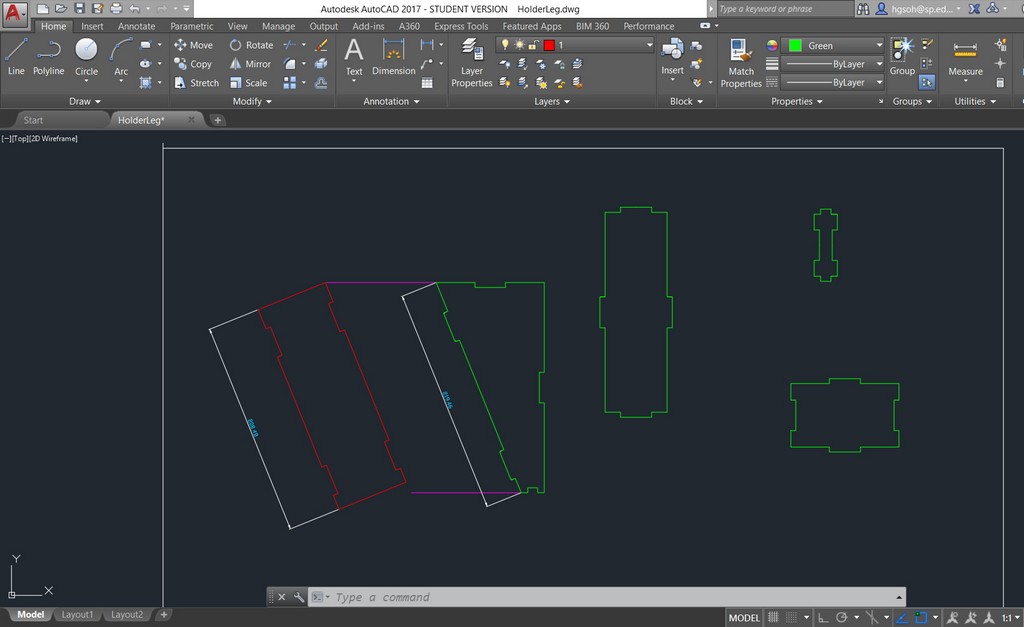
With the above constraint in mind I have came out with a simple design that conforming to the shape of the side profile of the laptop stand. The housing would enable the on board NTC sensor controller reside in it to be as close as possible to the left side of the laptop hot air exist channel. The housing designed in AutoCAD and final assembled circuit housing is as shown:
Testing of functionality of complete circuit
Thermistor circuit testing
After completed stuffing in of componrntd on the controller board circuit, I began on the embedded programming and the testing of the thermistor circuit temperature reading function just like the input week exercise13. This time round I added a AC fan as output that would be triggered "ON" when the temperature value equal or exceeded 32 degree C. I also have included in my Arduino coding to make the fan to remain "ON" even when the tempearature has declined from 32 degree C. This is to prevent the fan from switching "OFF" and ON when the temperature when temperature declined to less than 32. Further to that, I have also added a in my coding condition for the fan to remain "ON" between 32 to 30 Degree Celsius. These were to prevent the sudden turning "ON" and "OFF" of fan by the thermistor sensing circuit when temperature flutuate between >32 degree Celsius and < 32 Degree Celsius.
.A two parts video capture of the temperature sensing and turnning of fan are as shown:
The thermistor temperature sensing function coding in arduino IDE is as listed below:
     #include <SoftwareSerial.h>

     #define LED PB2
     float Vo;
     float SeriesR = 10000;
     float logRntc, R2, T, Tc, Tf, Rntc;
     float c1 = 1.009249522e-03, c2 = 2.378405444e-04, c3 = 2.019202697e-07; //Derived from Steinhart equation.

     const int rx=PB1;
     const int tx=PB0;
     SoftwareSerial mySerial = SoftwareSerial (rx,tx);


     void setup() {
     mySerial.begin(9600);
     }

     void loop() {

     //mySerial.println(Vo);
     //Rntc = Rseries*(1023/ADC-1);// for pull down
     //Rntc = Rseries/(1023/ADC – 1)); // for pull-up configuration

     Vo = analogRead(NTCPin);
     Rntc = SeriesR * (1023.0 / (Vo - 1.0)); //pull up configuration: pull downn Rntc=SeriesR*(1023/Vo-1);
     logRntc = log(R2);
     T = (1.0 / (c1 + c2*logRntc + c3*logRntc*logRntc*logRntc));
     Tc = T - 273.15;
     //Tf = (Tc * 9.0)/ 5.0 + 32.0;
     //mySerial.print(Tf);
     // mySerial.print(" F; ");

      mySerial.println("Current Temp in C:");
      mySerial.println(Tc); // display Celcius
      delay(1000);

     //if (Tc >=32){
     mySerial.println("ABCD"); //To test whether programme functioning-Extra.
     //digitalWrite(LED, HIGH);
     //delay(100);
     //digitalWrite(LED, HIGH);
     // delay(100);

    }
Manual on/off light testing from Serial Monitor.
To manually turn on/off of LED lighting also required me to have a seperate programme in arduino IDE as illustrated
    /*
     Laptop Stand Control Project


     by Soh Hong Guan
     6 June 2017

    */

    #include <SoftwareSerial.h>

    int LEDPin = PB2;
    int FANPin = PB4;

    const int rx=PB1;
    const int tx=PB0;

    SoftwareSerial mySerial = SoftwareSerial (rx,tx);


    // the setup function runs once when you press reset or power the board
    void setup() {
    // initialize digital pin LED_BUILTIN as an output.
    pinMode(LEDPin, OUTPUT); //Light Relay connected to this pin
    digitalWrite(LEDPin, LOW);
    pinMode(FANPin, OUTPUT); //Fan Relay connected to this pin
    digitalWrite(FANPin, LOW);
    mySerial.begin(9600);  //initialize baud rate 9600
    }

    // the loop function runs over and over again forever
    void loop() {

    if (mySerial.available()){
        char c = mySerial.read();
    if (c == 'R') {

      //mySerial.print(c);
      LEDON();
     }
    else if (c == 'S'){
        LEDOFF();

      //mySerial.print(c);
       }

    else if (c == 'T') {
      mySerial.print(c);
      FANON();
         }
    else if (c == 'U'){
          FANOFF();
      mySerial.print(c);
       }
    else if (c == 'V') {
      LEDON();
      FANON();
      //mySerial.print(c);
       }
    else if (c == 'W'){

      FANOFF();
      LEDOFF();
      //mySerial.print(c);
       }

    }}

   void LEDON()
   {
    digitalWrite(LEDPin, HIGH);
   }

   void LEDOFF()
   {
     digitalWrite(LEDPin, LOW);
   }

   void FANON()
  {
   digitalWrite(FANPin, HIGH);
  }

  void FANOFF()
  {
     digitalWrite(FANPin, LOW);
  }
Basically, my coding was able to perform the manual turn "ON"/ turn "OFF" of lighting function in Arduino IDE Serial Monitor Environment. While testing was being performed the following video was being captured:
Design of User Interface with VB.net to turn on/off LED and Fan manually.
Following the success testing of thermistor sensing input to turn on/off fan as out put automatically, and also manual turnning on/off of both LED and Fan control using serial monitor, I proceed to design an user interface in VB.net for the manual control of LED and Fan ON/OFF.
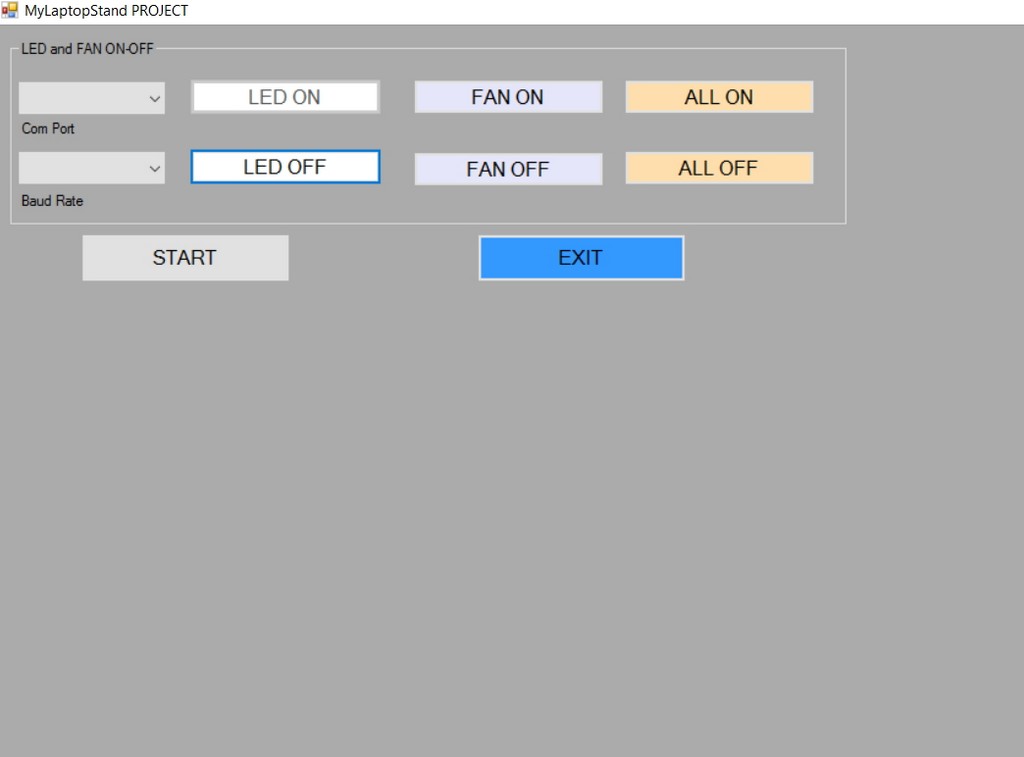
A video capture of the user interface testing is as shown:
Final Project Integration
With the success in testing of individual function and housing for the circuitry being made, I proceed to integrate the two function together with additional few lines of coding in arduino IDE. The programme is as attached in the work files download section.
Download work files
References
- Arduino Programme for Thermistor Sensing in Adafruit.
- Explaination of Steinhart Equation for pull up and pull down circuit.