Final Project Presentation
Project Proposal Project Planning Project Documentation The Build Processes, Testing and Results Final Project Presentation
Are all the tasks completed? (Yes, all done.) and & questions answered? (Yes)
What is the deadline? How much time do I have left?
There are 2 deadline to be met. First is to be ready for the presentation on the 19 June and second to be ready for the closing of Projects Repo on 28 June for uploading of report and work. The target is to be ready for the presentation meaning complete the testing of the individual part and then follow by the integration and testing with full assembly. Not forgetting also to create the presentation slide and movie clip. After the presentation will be follow up by loading up of the various report contents.
What questions need to be answered?
All questions asked have been answered! No major question arised
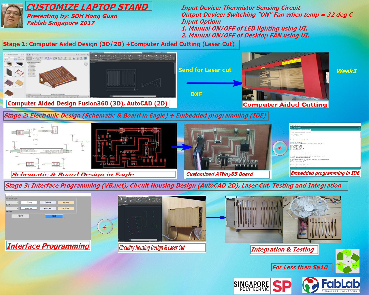
- What is the size of mechanical designed frame that is effective to provide an inclination/ allevation to the laptop? Answer: Actual measurement is being taken and the laptop stand was designed parametrically in Fusion 360 in 3D and the DXF file exported to AutoCAD for cutting out the physical parts of the laptop stand.
- How to design circuitry for remote control/ automatic control of the on/off of lighting and fan? Answer: As the laptop stand is place right in front of the control circuitry, using a UI design and coded in VB.net rather than remote control.
- What type of fan/LED lighting should be used? DC external of AC External? 5V or 12V? Answer: Both AC Fan and AC LED lighting were chosen by using comercial Relay module as a mean to control ON/OFF of the devices. No need to worry about the digital circuitry has not enough current to turn ON both Fan and lighting concurrently.
- What other components/ modules are required to provide enough electrical current to the circuitry intended to design for this project? Answer: 2 Commercial Relay modules were being used to provide the sufficient electrical current.
- How will the type of output devices affect my circuitry design? Answer: An LED light that can be kept inside the circuitry housing proof to be handy and served the purpose of night lighting. While a dual usage desktop fan are useful for cooling down the laptop and provide some breeze to the user. Both worked fine and neatly to my satisfaction.
- How to code the programme to do what I want it to do? Answer: Using IDE, two seperate programmes for fan and lighting were being coded and testing individually. After tested, both then being integrated to perform the functions required.
What tasks needs to be completed?
All the tasks planned had been completed as according to schedule.
- Mechanical design of physical laptop stand in Fusion 360 and prepare the DXF files for laser cutting. Done! Since week3 and have been using the laptop stand with out the electronic control circutiry.
- Designing circuitry schematic and board design on EAGLE. Done! Both Sechematic Design and Board Routing were completed and PCB board produced just in time for the embedded programming in IDE.
- Designing the circuitry and housing of external bypass/ control switch. Done. After using the laptop stand for more than four months, found that the structure are quite well in tact with 5 mm thick ply. On the same analogy - Circuitry housing was design in AutoCAD to conform to the side profile of the laptop stand and the housing were produced using Computer Aided Cutting using Laser Cut.
- Programming the microcontroller to monitor temperature and light intensity for automatic control and manual control using either Arduino IDE, or C programming. Done! As part of the spiral development, temperature monitoring and automatic control of Fan ON/OFF, Lighting ON/OFF were included. The programming platform was in Arduino IDE.
- Designing and fabricating a housing for the PCB circuitry using 3D printing technology? Not Done! Substitute with computer aided design and control cutting. Because the size of the housing and shape need to be conformed with the side profile of the laptop stand. It would take quite a long time to 3D print.
- Designing and faricating of holder for lighting and fan. Using the same crcuitry holder and correct choice of LED lighting sizes, which enable the light to be stored in the holder. A desktop fan was chosen and it it being place at the back of the laptop stand. No holder for fan is required.
- The actual assembly of the electronic and mechanical components into a working prototype. Done! Integration electronic circuity in the holder and laptop stand work perfectly. Temperature sensing in non aircondition room as well as i aircondition room were being tested. Prototype created is fully functional with both automatic and manual control to turn on both fan and lighting.
What has worked?
All planned functions have been working fine
What hasn't work?
All working fine and stable.
Future Plans for Development
- The temperature control and light on-off circuitry could be improved further rather than using just an user interface to control, I would like to explore how to modify the board for controlling; using bluetooth with a handphone app develop using MIT apps inventor.
- Another area that I would like to explore is perhaps to redesign my lighting and fan holder in my next prototype to integrate all into one complete integrated unit with night light/ reading light and dual function fan.
Continuous Improvement (Prototype Revision 2.0)
As part of the continuous improvement, I have revisit 3D Design in Fusion 360 to design a lamp holder for my salvage/ recycle LED light. The salvage LED spot light was originally purchased from IKANO store in Singapore by one of Diploma student in Singapore Polytechnic Design School. The LED light come with a diammeter of 50mm with outer cover and a thickness of 20mm. I would need to design a holder that can be incorporated into by existing circuit holder, with feature that enable this LED light to be tilted at certain angle and 3D print the holder.
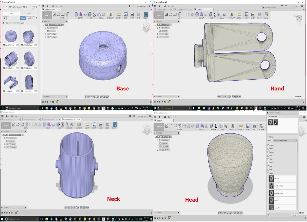
I then proceeded and modified to size the individual parts of the LED lamp holder. I named them base, neck, head, and hand of LED light holder as illustrated in the following picture.
The STL files for the lamp holder is avaialble in the following zip file.
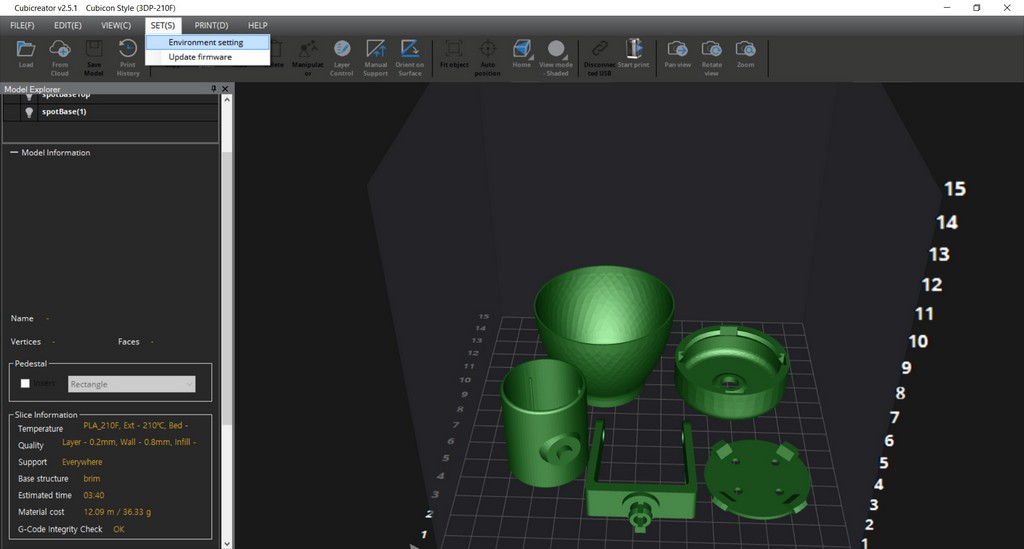
Next up, I proceeded to imports all the individual STL files for the LED lamp holder into CubiCreator software as I am using a cubicon 3d Printer at the our Makerspace at Library. A screenshot of all the lamp holder parts was captured and illustrated below:
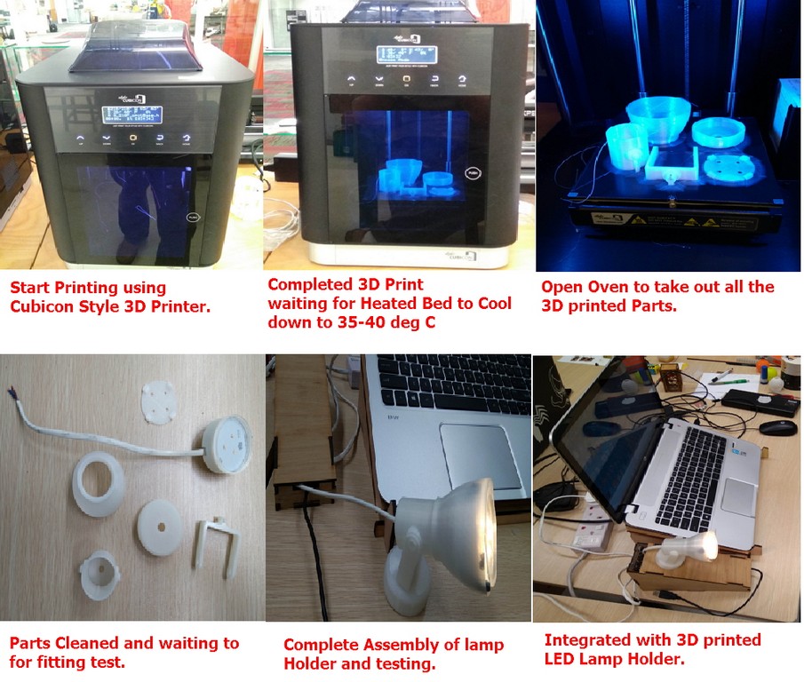
Following that, I copy this hvs file into a SD card and transferred to the Cubicon 3D printer to print out my lamp holder. After waited for all the parts to be printed and the heated bed to cool down to between 35~40 Deg C, I then removed the parts from the Cubicon Style printer, did the routine peeling out and removal of support structures. The follow by cleaning, assembly of parts and test fitting. Subsequently, then I tested the lighting after assembly and proceed to attempt the integration. The entire processes are as illustrated in the following pictures.