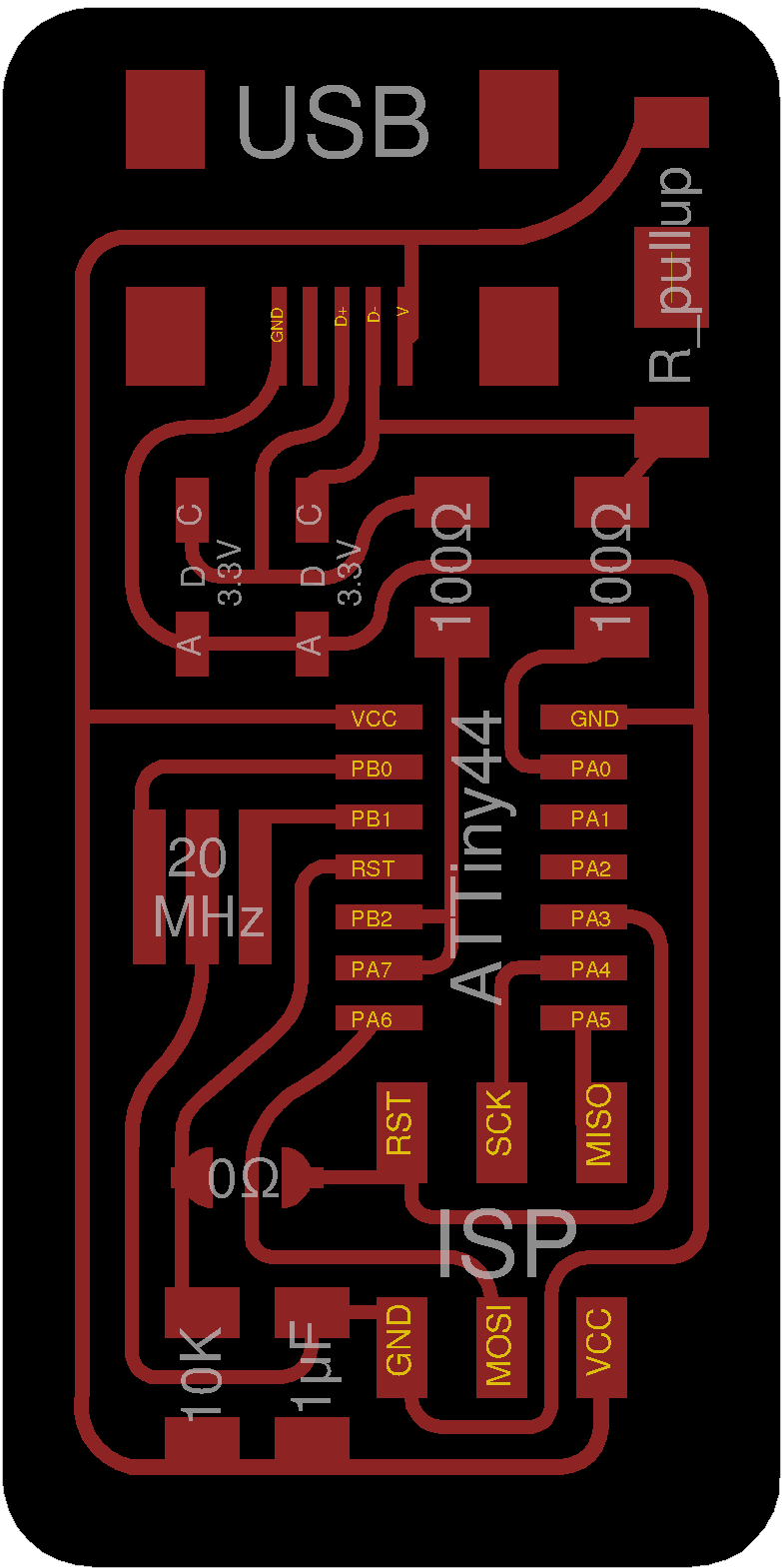
Assignment: make an in-circuit programmer by milling the PCB, then optionally trying other processes.
As far as I understood, I learned...
From the lecture:
- Instead of etching, machining is safer and environment-friendly.
- Interesting things: conductive thread, flexible material such as copper foil and epoxy film that can cut in vinyl cutter.
- Use 1/64 for the traces, 1/32 for the outline.
- If the end mill gets dull, we can lower it a little bit more.
- FR4 can endure more heat, but FR1 is good enough for us, and it can keep the life of the end mill longer.
- If we want to use high frequency process, then we can vinyl cut, and transfer it to glass.
- If we need to make more than 10 pcb, it is better to order them at some board house.
- These days, hardly use through-hole components. Instead, we will use the surface mount device (smd) the most (and just a little chip-scale components since they are hard to solder).
- Breadboard: bad electrical property, unstable, wires easy to tangle
- When mistake happens: pcb solder jumper to fix
- Flux prevents soldering from flowing to the side.
From the meeting:
- We will teach programable teacher-to-be (yet, just student) using progammer teacher.
- Once these new teachers learn how to program, they cannot learn any more. That is, they become teaching and programing mode, but no more student mode.
- Thickness of the copper layer in PCB: 0.1015mm
- Soldering order: more to less, center to outside, small to bigger, but always from difficult to easy.
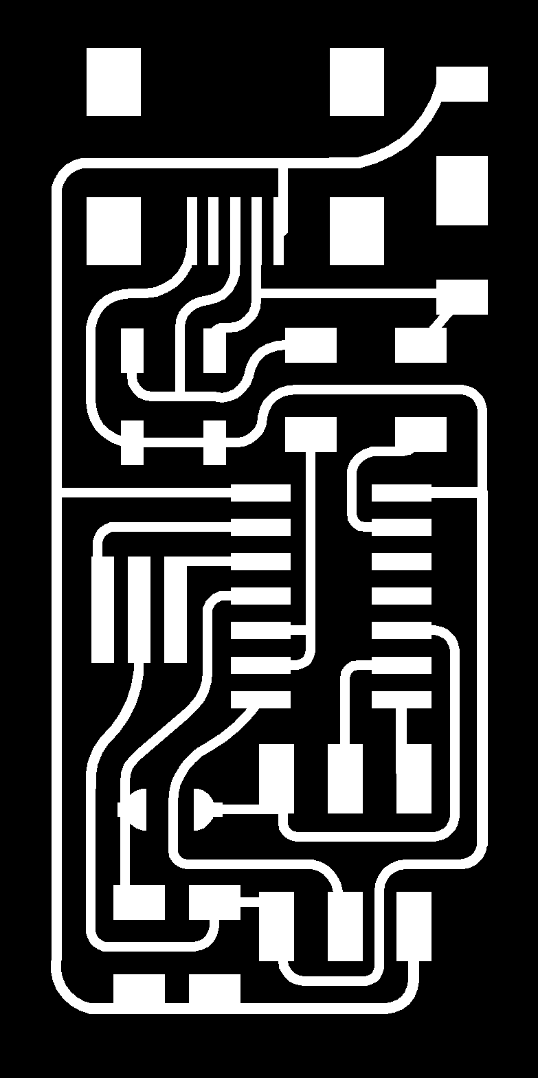
- while milling, the end mill will cut the boundary where the black and white regions meet, and it will cut the black side (it won't touch the white part). Keep this in mind when you design the thickness of the line.
- I heard that it is more stable to use separate usb component although it is hard to solder.
- Since we don't have 1.5K resistor, I used FabOptimus2 (with 1K+499Ohm). - Check the resolution of these png files!!
Settings in fabmodule:
1. Trace:
- Prepare png file.
- Go to fabmodules - 'input format > image (.png)', and then the trace file.
- 'output format > Rolland mill (.rml)'
- 'process > PCB traces (1/64)'
- Check if the dimension looks reasonable.
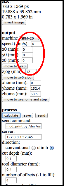
- Output machine: choose machine SRM-20
- Speed : 4(normal) or 3(if the end mill is new)
- Set x0, y0, z0=0
- Set zjog=12 (zjog: the height of the lifted end mill when it moves to different line. 12mm is safe)
- x, y, zhome: kind of parking place after finishing working. Don't need to change them.
- cut depth:0.1 (in one cut) (default)
- tool diameter 0.4mm = 1/64in (default)
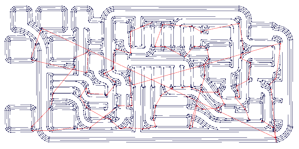
- Push 'calculate' button: blue lines are for end mill cutting, red lines for moving from one line to another.
- Set number of offset=4. (we can remove all the black part, or cut only near the white region. Setting this to -1 will remove all the black part, so it is safe, but it takes longer time. Setting this to 4 will cut 4 lines outside the white region, and is good enough. I have one more tip. Here: Note 1)
- Save this as .rml file.
2. Outline:
- Refresh the window to start with a new file.
- input format, output format: the same, but most importantly, 'process > PCB outlines (1/32)'
- Check if the dimension is the same as the trace.
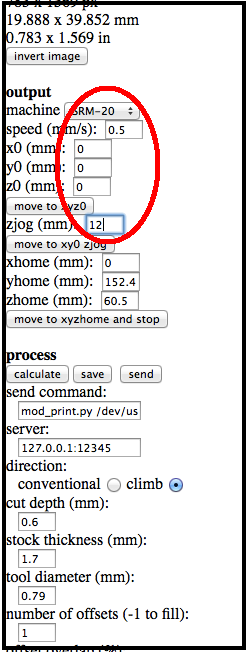
- Another important change: same machine (SRM-20), but different speed!!! Set speed= 0.5. In case of really big hurry, maybe 1 is okay, but 0.5 is still better and safer. Never leave speed=4.
- Set x0, y0, z0=0 (or the same points as in the traces).
- cut depth=0.6, stock thickness-1.7mm (default)-->It will cut 4 times.
- tool diameter: 0.79mm = 1/32 in (default)
- number of offset=1 (It only needs to cut the boundary) (default)
- Click 'calculate' button, rotate it, and then you can see that it will be cut in several layers.
- Save this as .rml file.
-->move to usb
Milling with Rolland mill:
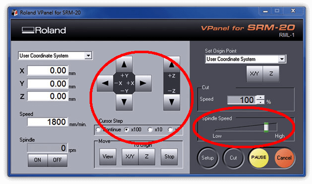
- Turn on the machine and click the icon for the machine (VPanel for SRM-20).
- Need to warm up: (if the machine was already on, there is no need to warm up.) Set the spindle speed to be the middle or lower (when milling, it should be set to the max). Let it run for 5-10min. To save time, we can do this first, and in the meantime, work on the fab module setting.
- You can control the movement manually. x, y, z axes. Move it to the center, and lift it up so that I can do the following:
1. (I don't know its name.) Install this first. It should screw smoothly. When it gets a bit tight, use two wrenches (different size) to fasten it a bit more. Do it gently.
2. Put the end mill (1/64 for the trace, 1/32 for the outline). Always push it gently from the side with your finger. It will keep the end mill from falling down. Push it up, and then fasten it gently with the Allen key.
- (Optional) Wash the copper board (mostly we will use 1 layer copper board) with water or alcohol to remove finger print. I didn't.
- Put double-sided transparent tapes underneath. No overlap, no bubble, still cover almost the entire board.
- Clean any left over tape or other dirts off the platform using spatula, put the board, and then push it hard with some cloth. You can take out the platform.
- Move the end mill to the point where you set to the x/y origin (left lower point of the png file).
- Note 2.
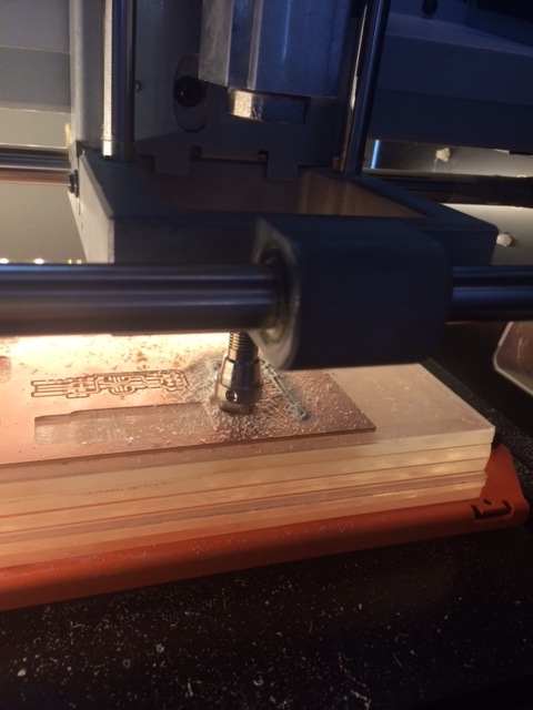
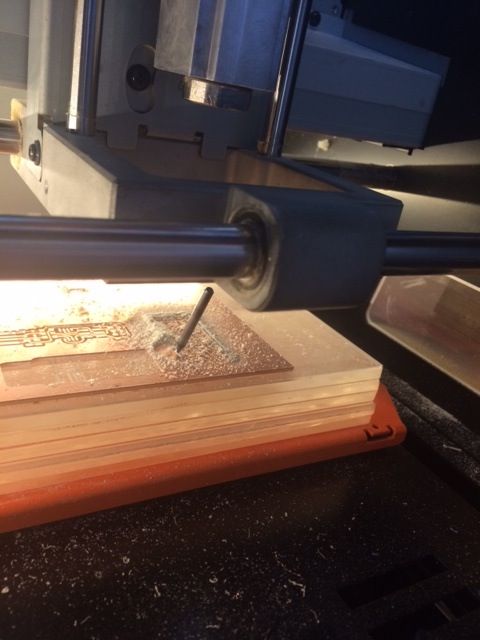
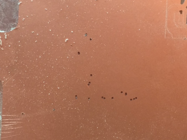
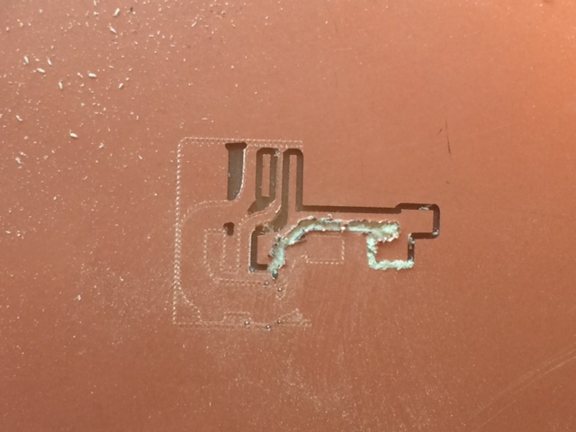
- Lower the end mill close to the surface. Then using allen key, unfasten the end mill carefully with your finger supporting it from the side, and then lower it carefully to the surface of the board. Carefully, but firmly push the board down so that the end mill can also get lowered a little, and then fasten it again. I fastened the end mill, but not properly, so it fell down in the middle of milling. So I broke one 1/64 end mill. - Set this to be the origin for both x/y and z. This is really important.
See what happens when you don't this step properly: What happened? For the details: Note 3.
- Ready? Then click cut, and then delete previous work, add the new one, and start to mill it.
- When the trace was cut, change the end mill (to 1/32), lower it to the gently pushed surface, and then set the new origin only for z!! (x/y origina should remain the same.) - Change the file into the file for the outline, and start milling.
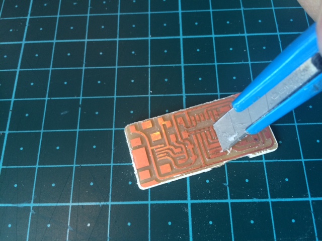
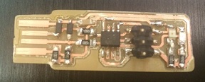
- When it's done, take out only my part. If I take out the whole copper board, then the tape will lose its stickiness. - Clean it with a box cutter. Remove all the small pieces that is not parts of the circuits (Even the copper layer. See Note 1 again). Gently sweep the surface with the top edge of the cutter.
Mistakes I made:
1. When I changed to outline cutting, I forgot to change the end mill to 1/32. But I noticed it before it starts milling.
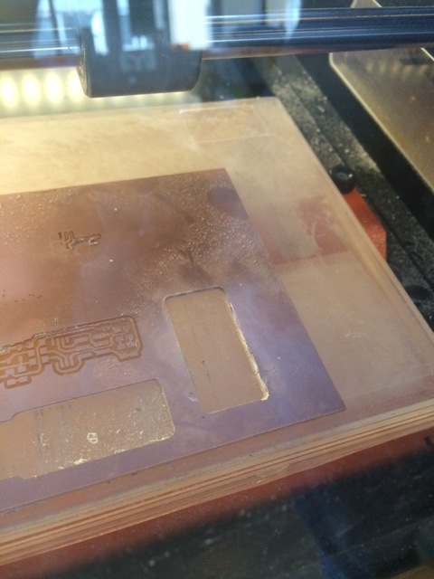
2. I didn't check if the board was really flat or not. So it failed milling the surface properly, and I had to change the tape. See Note 2 again.
3. The .rml file I got from the fabmodule using my mac was weird, and discontinuous like the below. It becomes continuous when zoomed in, so I used this at first, but it gave very strange result. I don't know what the problem is, but it was fixed when I used different computer (which is still mac).
4. As for the one I broke, I thought I fastened enough, but maybe not. Maybe I felt some tightness not from it, but from my holding the allen key in a skewed way?
5. Once again, I forgot setting new origin for z..
6. Maybe not a mistake, but I removed the tape after I took out PCB from the machine. And I realized that it is much easier to solder if I keep it.
One more mistake..I forgot how this happened.
2. Soldering the PCB
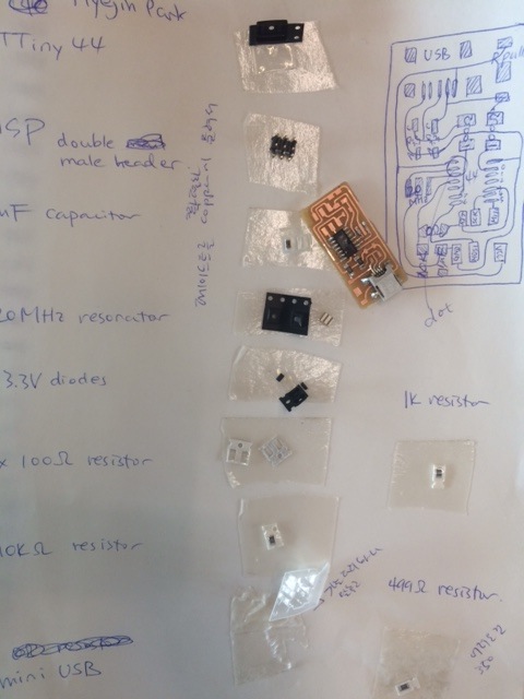
Before start, make a list of all the needed components on a piece of paper, and place those components on double-sided tape.
(Don't forget to check what I used in the inventory.)
Now soldering
- Soldering iron: always keep it at its own stand. The sponge should be wet.
- Putting the board on a small plate makes it easy to rotate the PCB.
- Wire: don't use the whole roll. always use cut piece.
- Modification: suction, liquid/solid flux, braided copper wire
- Magnifying glass: optional. I didn't use it.
- Use fan to filter the smoke.
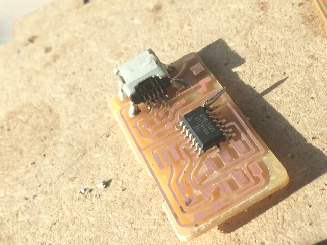
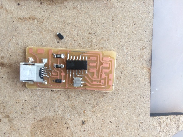
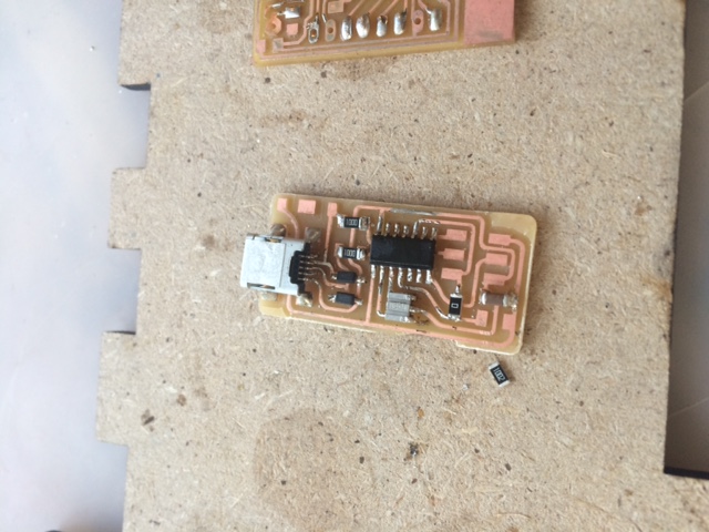
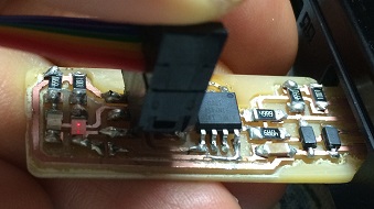
- Start from the most difficult one: mini USB
and then microcontroller (ATTiny 44): be careful with the direction! See where the dot should be located here.
(It is really easy to make this kind of pointed thing (at a leg of ATTiny44), but not easy to get rid of it.)
- One more component with directionality: diode. The line should be on cathode(-) side.
- For the rest, just follow the suggested order: more to less, center to outside, small to bigger.
Comments:
- Components with many legs: 1) put a little bit of solder on the board, and then place the component with soldering iron applied. 2) fix another leg on its diagonal position. 3) solder the rest.
- I couldn't put adequate amount of solder on each pin, so those small legs were always combined and covered with the excessive solder. A visitor to fablab seoul taught me a very good trick. 1) spread the tip of braided copper wire wide, 2) dip just a little to the solid flux, 3) place it on the excessive solder and put the soldering iron horizontally on it, and 4) if the solder gets absorbed, take the copper wire first, and then soldering iron.
- I didn't clean the tip of the soldering iron often, and it caused dirty result.
- Set the temperature to 300 for the normal ones, and to something higher (~350) for the difficult ones, or for desoldering.
3. Programming FabISP
- I didn't succeed in this step. I successfully programmed it (make clean, make hex, make fuse, make program), but it was not recognized as a USB device. So I tried to take out the miniUSB component and then resolder it, but by mistake, I damaged the board, so I had to make a new one. This time, I used Brian's FabTinyISP files. (Soldering process is the same)
- To program it, I downloaded firmware, and then tried to follow the same step, but it didn't succeed at 'make hex'. So Edu helped me with the following step:
'make clean'>'make'>'make flash'>'make fuses'
Then check if it is recognized as USB, and if so, 'make rstdisbl' (meaning, reset is disabled now)
Note:
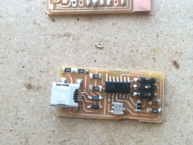
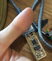
I desoldered jumper since it is no more needed, but it made the led light quite weak.
So I connected them again. I don't need to worry about resetting it by accident since I already disabled reset button. The light is much brighter now!
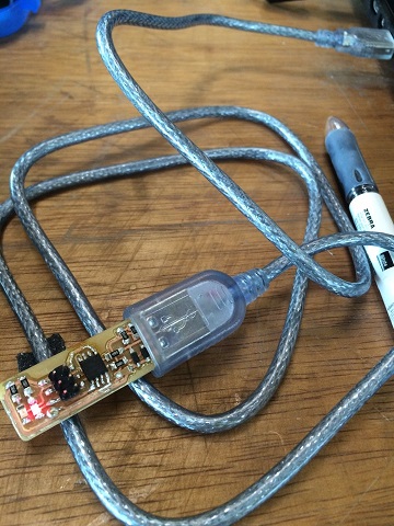
I also connected my usbtiny to USB line so that I don't need to connect it to the computer directly whenever I use it. (The connecting part can be worn down easily.)
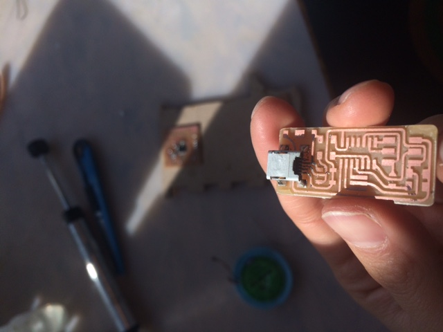
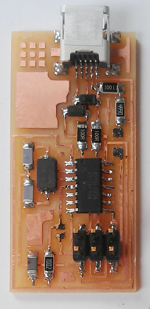
Hmm.. my instructor asked us to include a hero shot of the finished board. This hero will save the world!
0. Most importantly!! 'After you program the board, you must remove the 0Ω resistor, and you must also cut the trace leading to the VCC pin on the 6-pin programming header'!!
1. Programming FabISP requires the RESET pin (of MCU) to be pulled low (RST of 6pin header: connected with 0K resistor), but then pulled high (10K resistor) to prevent reprogramming. So after programming, remove 0K resistor.
To use FabISP as a programmer, we need to provide reset signal to another board. To keep the control over it, there should be connection b/w RST and I/O pin.
2. Decoupling capacitors b/w Vcc and Gnd reduce power supply noise.
3. ATTiny has an internal clock, but we can have higher speed and accuracy by having external clock: resonator
4. USB data lines: ~3.3V, the output of ATTiny I/O pins: ~5V --> voltage clipper by two 3.3V Zener diodes and two 100 Ohm resistors
5. To identify our board as a USB device to the host..: 1.5K pull-up resistor (+zener diodes,.. Hard to understand..)
6. Reason for disconnecting VCC pin in the 6pin header: any boards we want to program with FabISP would supply its own power.

 (I don't know its name.) Install this first. It should screw smoothly. When it gets a bit tight, use two wrenches (different size) to fasten it a bit more. Do it gently.
