Fabacademy 2017
Final Project
Index
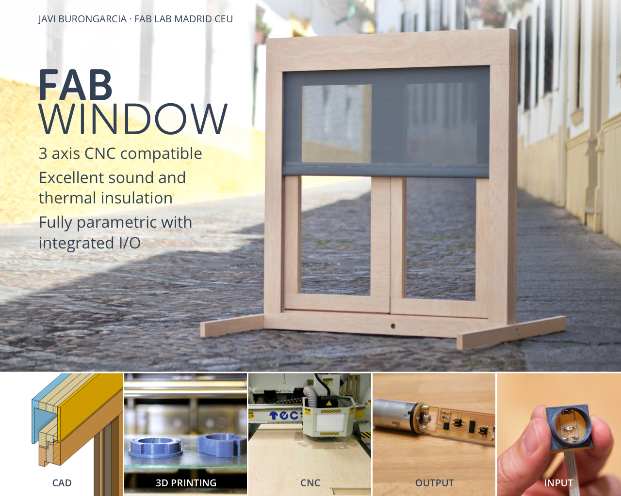
Fabwindow
3-axis CNC compatible with built-in I/O
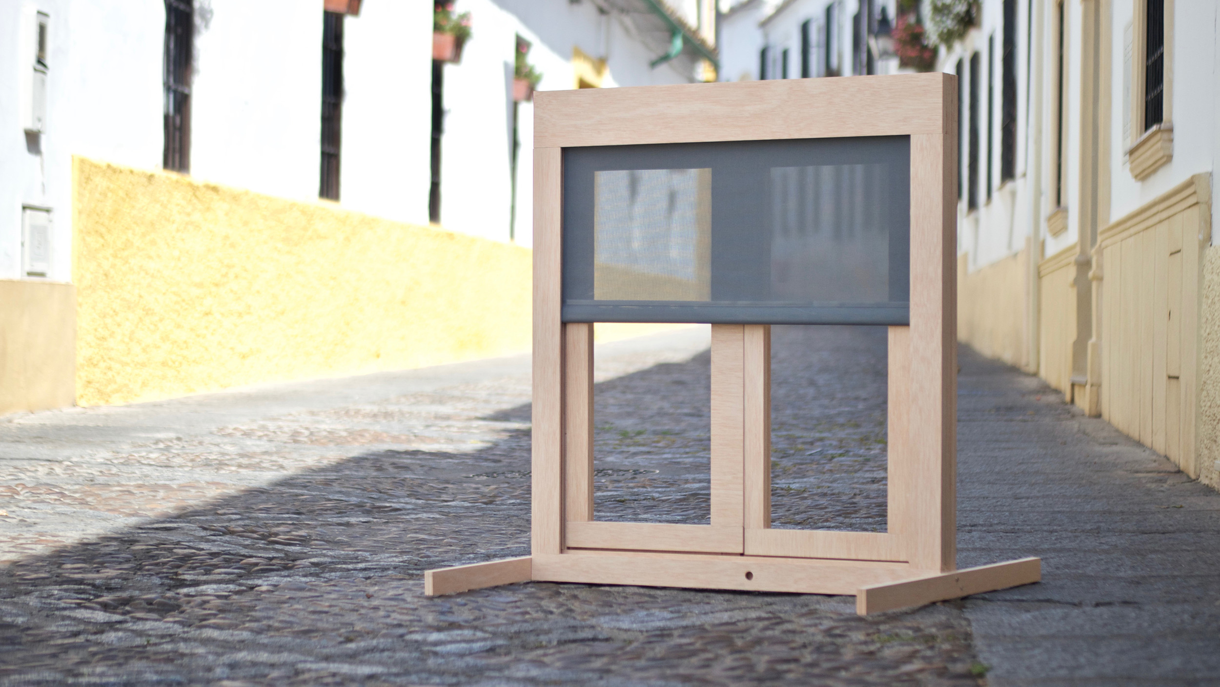
Fabwindow is a 3 axis CNC compatible design for high performance timber windows up to Eurocode standards. The design is fully parametric allowing extensive customization and adaptability to different glazing systems, seals and stock timber. The design has an integrated I/O approach so multiple sensors and actuators can be integrated into the frame. This first prototype has a light activated exterior roller blind to protect the glass from excessive sunligth exposure.
Parts
Parametric Design
The main objective of this part of the project is to create a design and manufacturing process for a high performance window that can be replicated in any fab lab with the standard Fab Lab equipment and accessible materials. Plywood is an interesting choice as it provides a good weight to strength ratio, decent durability and a broad range of qualities and prices.
A 8x4 flat CNC milling machine would be the preferred tool as well. In order to make the design accessible to entry users with limited skills, I will try to simplify the milling process as much as possible, avoiding complicated jigs and registration processes
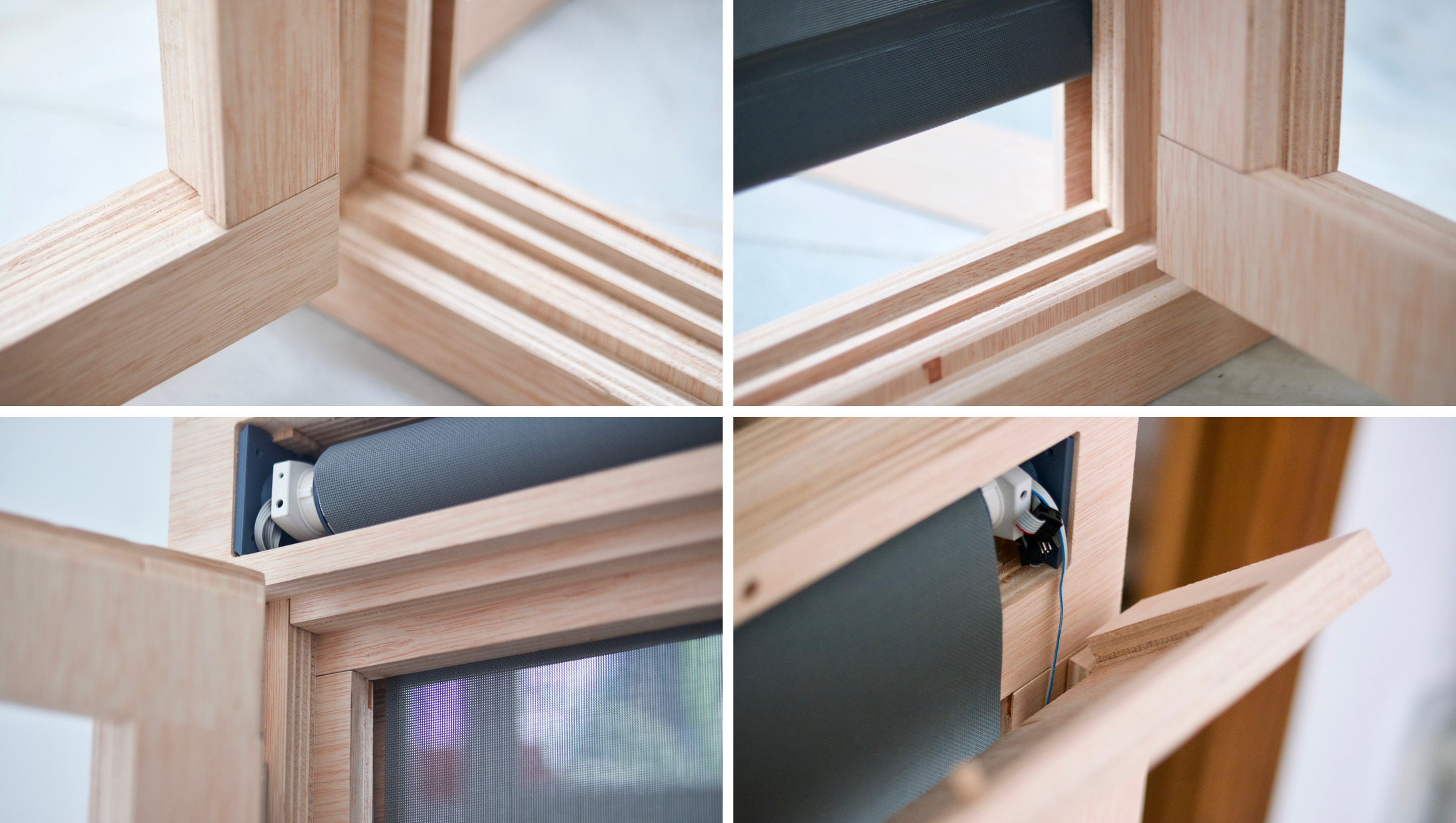
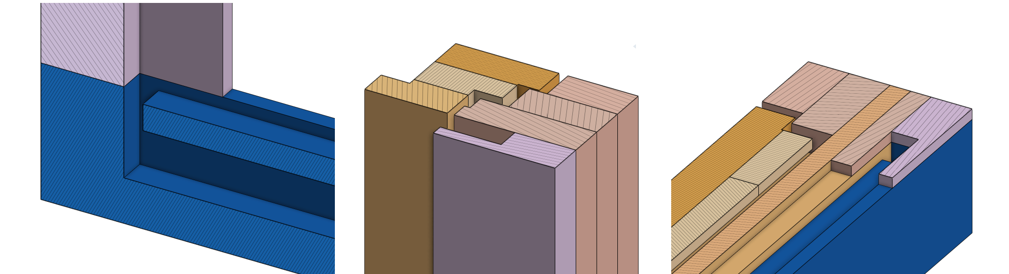
How to fabricate a complex timber profile which is normally made in multiple routing steps using dedicated (and expensive) tools and router bits? The first decision would be to achieve these profiles by dividing them in simpler sections –using simple pocketing and profiling operations– and assembling them later. There are certain shapes that will be much harder to replicate using this process by in exchange manufacturing and assembly process should be greatly simplified making the fabrication of a window a process that most people could undertake as a weekend project.
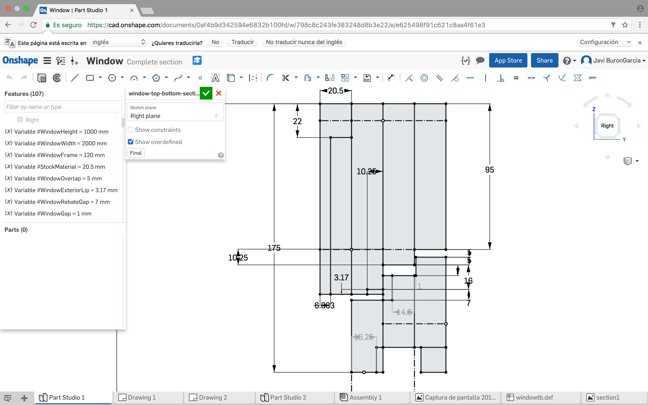
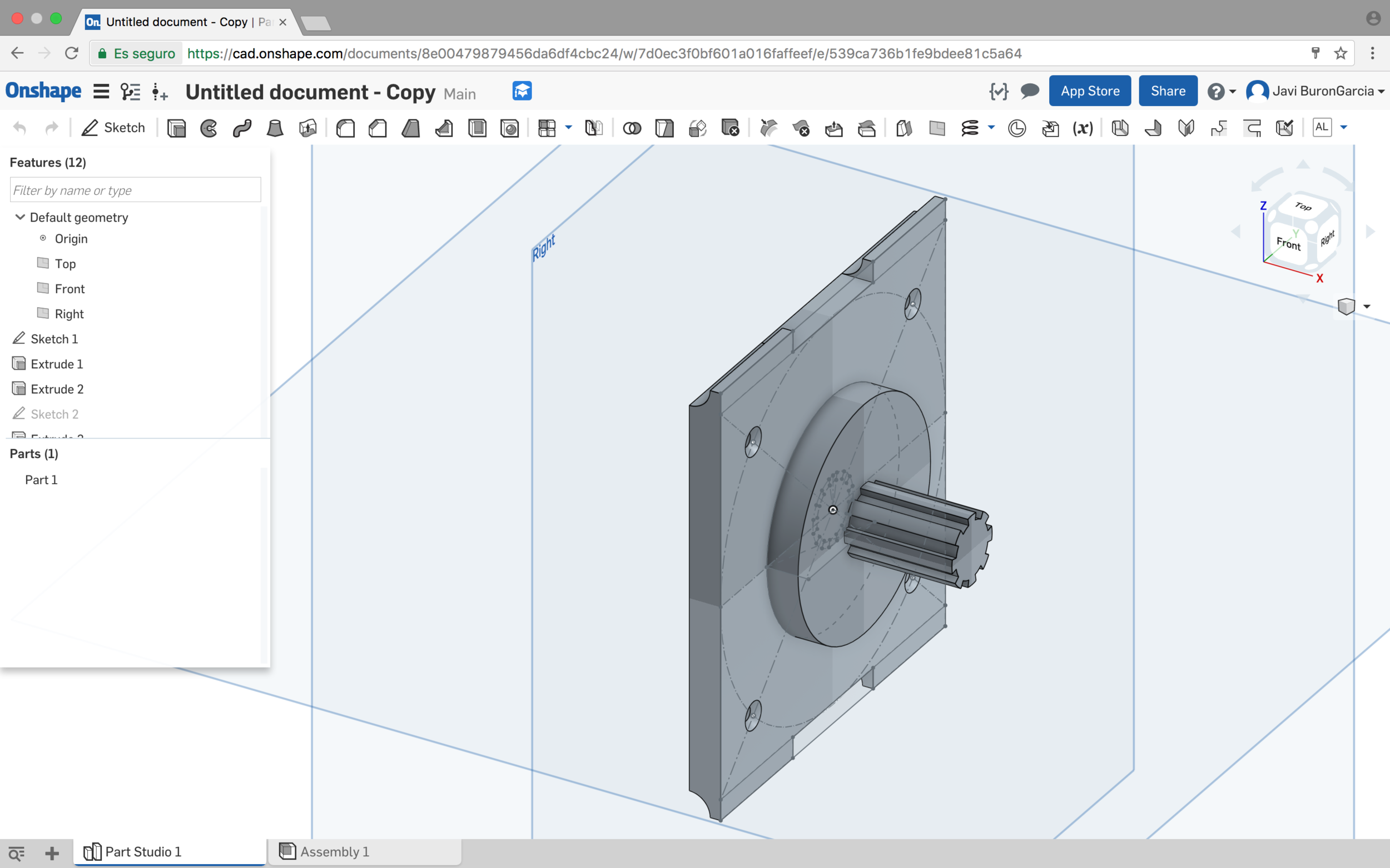
Design is done with Onshape and it is fully parametric so it can be adapted to any stock material thickness, glazing thickness, opening height and width and even gasket dimensions and seal gasp. There are 20 different parameters in total, this would allow a "pro" mode in which each parameter can be adjusted independently and a "basic" mode in which only the basic ones are accessible to the user.
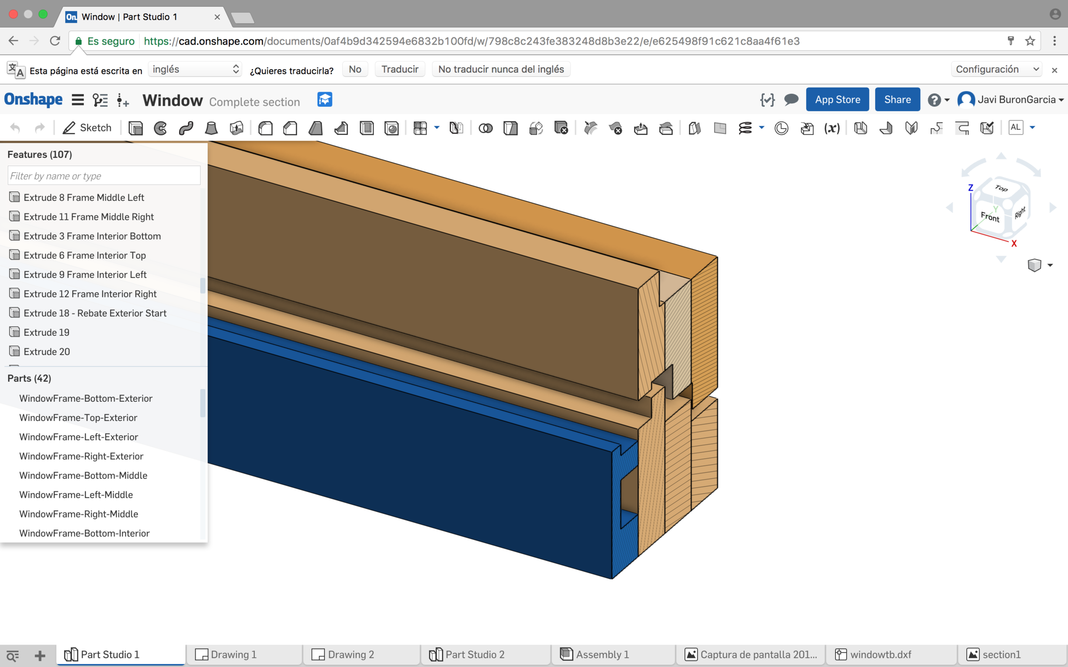
This "sandwich" design approach allows for creating internal holes within the structure to place sensors, actuators and cables. Some of this holes would be to be accesible for component upgrading and replacement.
Structure
Once the design was ready in Onshape, I created a drawing view lay out all the parts in the drawing and export it as a DXF 2D drawing. Then, I used vcarvepro for importing the 2D drawing file and generate the CNC paths. I cut this prototype at Fab Lab Madrid CEU, using a 2 flute endmill upcut 6mm bit for all the operations. The complete design uses holes of two different depths, six different profile jobs with different depths and two profile paths for interior and exterior cuts.
Please note that for budget restriction issues –I was not allowed to use more than one single sheet of ply for this prototype and my initial dimensions would have required two– I have to do a reduced version of the window 1000mm by 1200mm instead of 1200mm by 1600mm so I wont be able to install the window in my own house.
| Flutes | Pass depth | RPM | Feed Rate | Plunge Rate | |
|---|---|---|---|---|---|
| 6mm Upcut Endmill | 2 | 6mm | 12,000 | 3657 mm/min | 600 mm/min |
For the profile paths I used four tabs per piece of 10mm length and 0,8mm height, I added zig zag ramps to the path. For the pocket paths also used ramps.
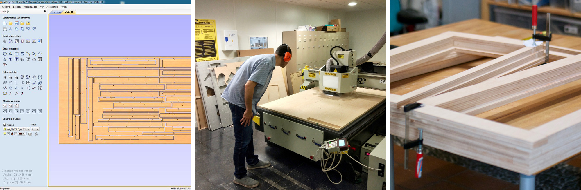
Once all the toolpaths are calculated and everything has been simulated a few times, I created CNC tap files and loaded them in the CNC. Fab Lab Madrid CEU CNC has a vacuum table so fixing the stock to the base with screws is not needed. Cutting all the different pieces –36 of them– took 2 hours and 30 minutes.
Back in Córdoba, I sanded all the pieces and proceeded to glueing and assembly. The complete process took half a day. Some learning from this process:
- Labelling is needed. pieces are quite similar and in order to simplify assembly labelling will be of great help. I made a couple of mistakes because I didn't plan for this.
- During the packing process some holes were misplaced, it is quite difficult to spot this errors once you leave the 3D modelling software so a more automated process is necessary.
- Everything fits precisely but I found that making sure that all the sections were square could be improved with some designs tweaks. Also not sure if it is best to assembly the structure in layers or assembly first each strut and them construct the frames.
In summary, I think with this process it is possible to transform a highly skilled woodworking task into a flat pack design that can be assembled with almost no experience with satisfactory results.
3D Printing
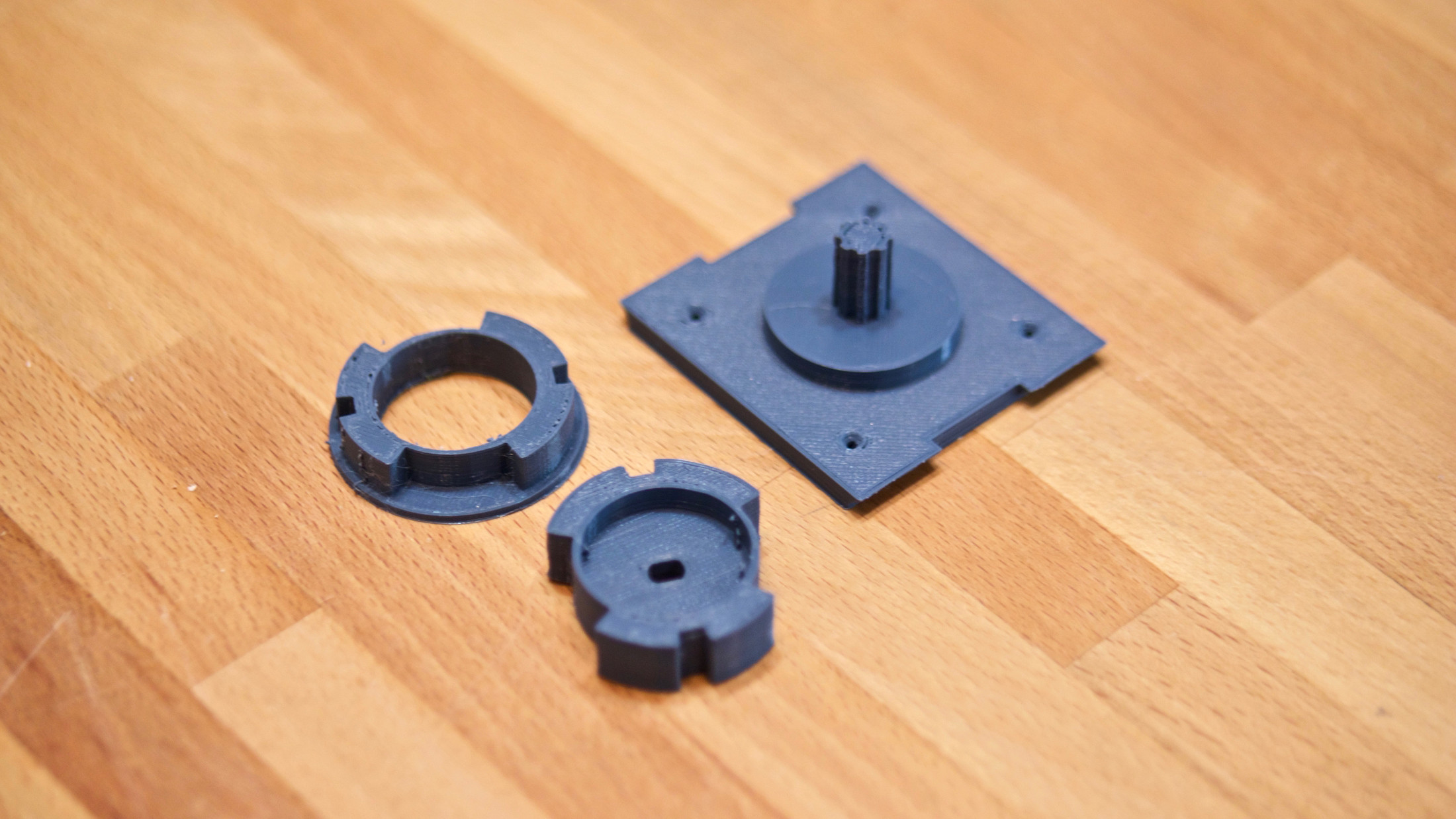
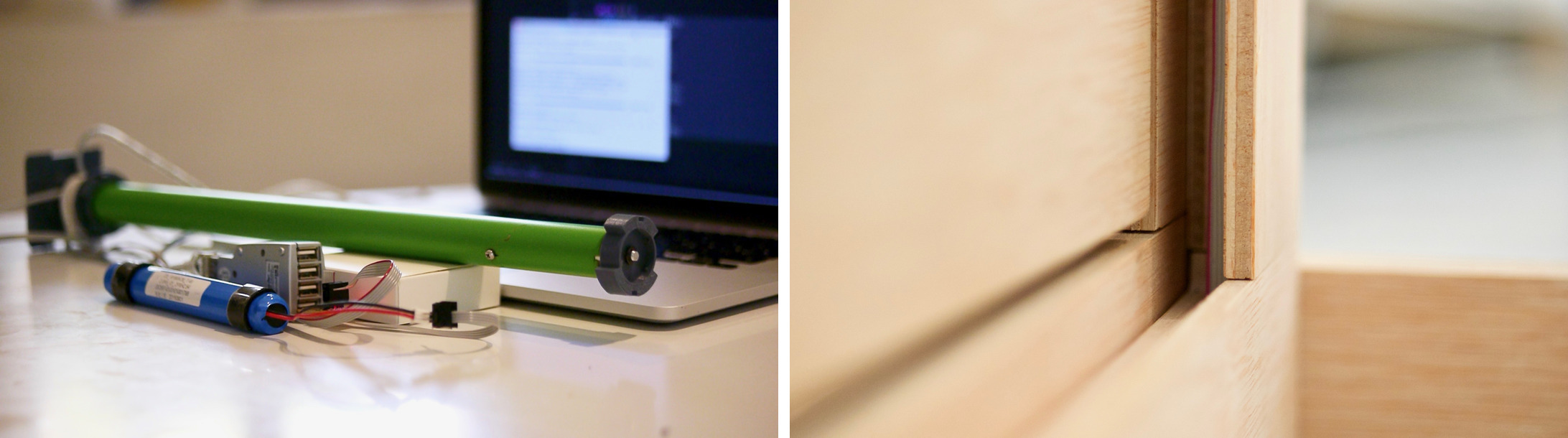
3D printing was used for tubular motor caps and roller blind holders. All these parts were created parametrically with Onshape so I could iterate fast and adjust dimensions in order to connect precisely with off the self parts.
Once the design was ready, I exported as a STL file, processed with Cura and printed it in bluegrey colorfab PLA 1.75 filamente using the following settings:
| Layer height | 0,1mm |
|---|---|
| Fill density | 100% |
| Print Speed | 100mm/s |
| Extruder temperature | 220ºC |
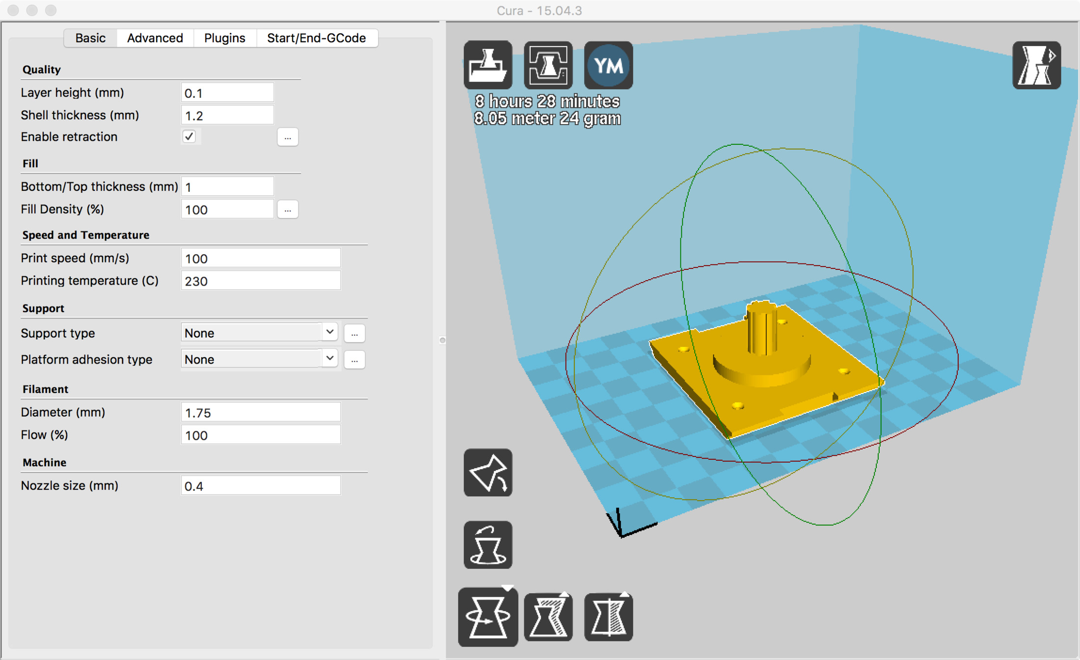
The other parameters are the official Sharebot Kiwi profile settings that can be found in their support page
I found Sharebot Kiwi 3D printer accurate and reliable, it doesn't have a heated bed so using more specialized filaments is always challenging but when using PLA the results are predictable and very consistent. Lately, I am using hairspray to improve first layer adherence on trickier prints with less surface contact with the base.
Output
This part will control a DC motor for the roller blinds of the fab window.
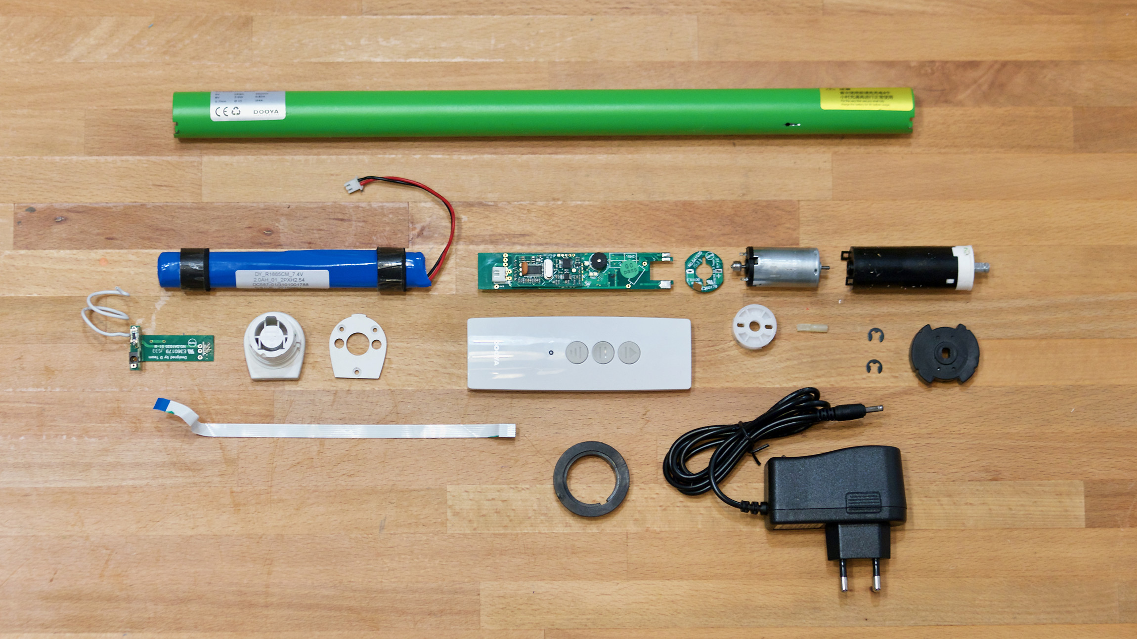
This is a good resource for calculating the necessary torque of a roller blind DC motor. I also found a manufacturer which provides DC motor and the reduction gearbox in a handy format that can be installed inside the roller blind inner tube so it will keep things much tidier than installing the motor on one side.
This specific model also includes a battery which I will use to power the whole system. It brings its own controller circuit with a built in radio receiver which they will not be used, I will be using my own designed boards. It needs 8V and 0.81 Amps.
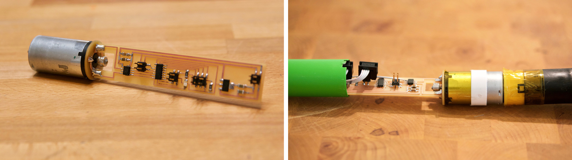
My Week 10 board was used as a reference. It uses the A4953 Full-Bridge DMOS PWM Motor Driver which as its datasheet state "…is capable of peak output currents to ±2 A and operating voltages to 40 V". The chip has an exposed thermal pad for heat dissipation. I changed the regulator from the LM3480IM3-5.0/NOPBCT-NDto a 5V 1A SOT223-3 voltageregulator capable of a maximum output current of 1A.
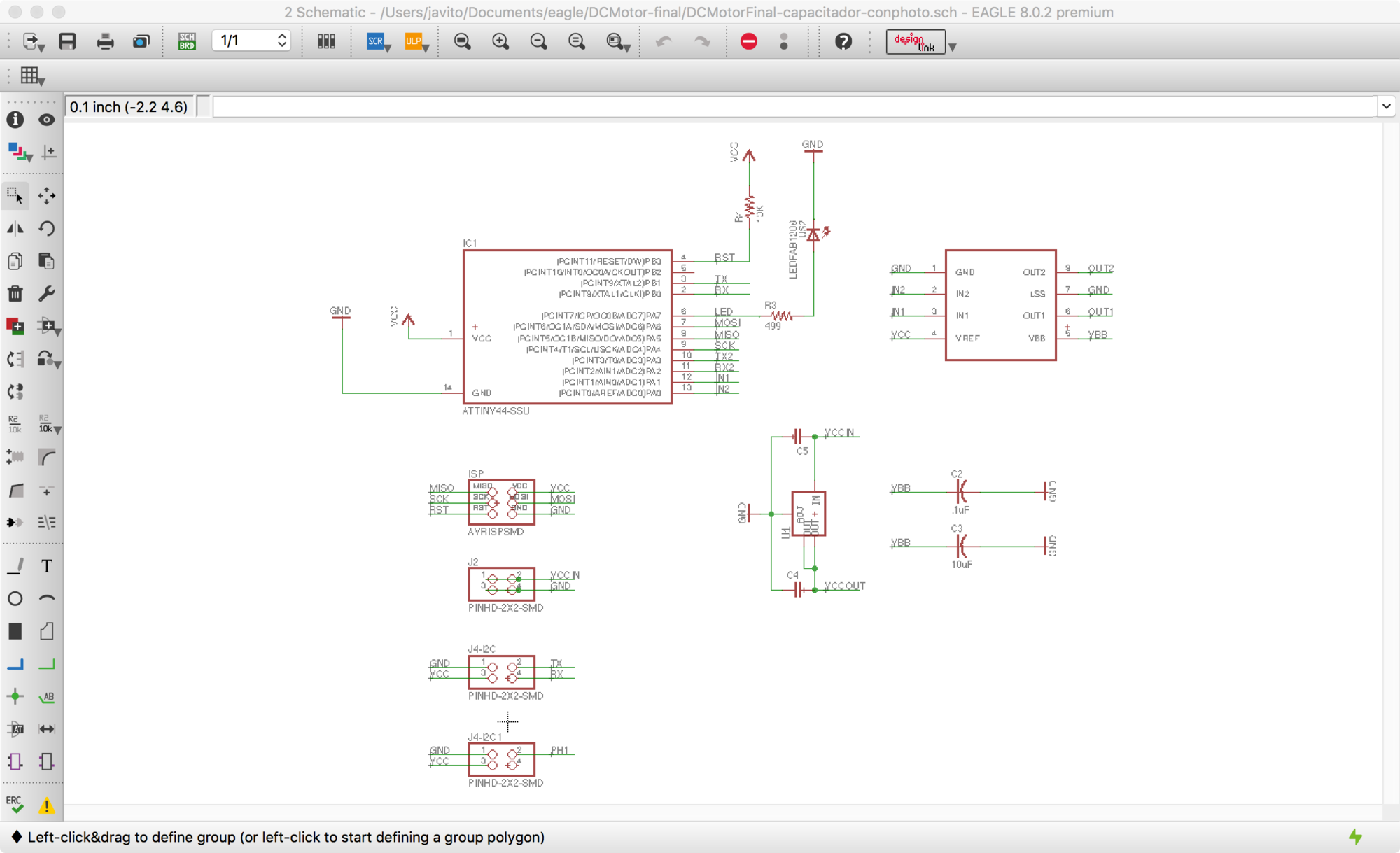
The major changes on the physical design were to make sure that the board was less than 22mm high so it could fit inside the steel tube of the DC motor. Also I made a small circular board –similar than the one used in the commercial board– that allowed me to attach the dc motor in a neat way to the board.
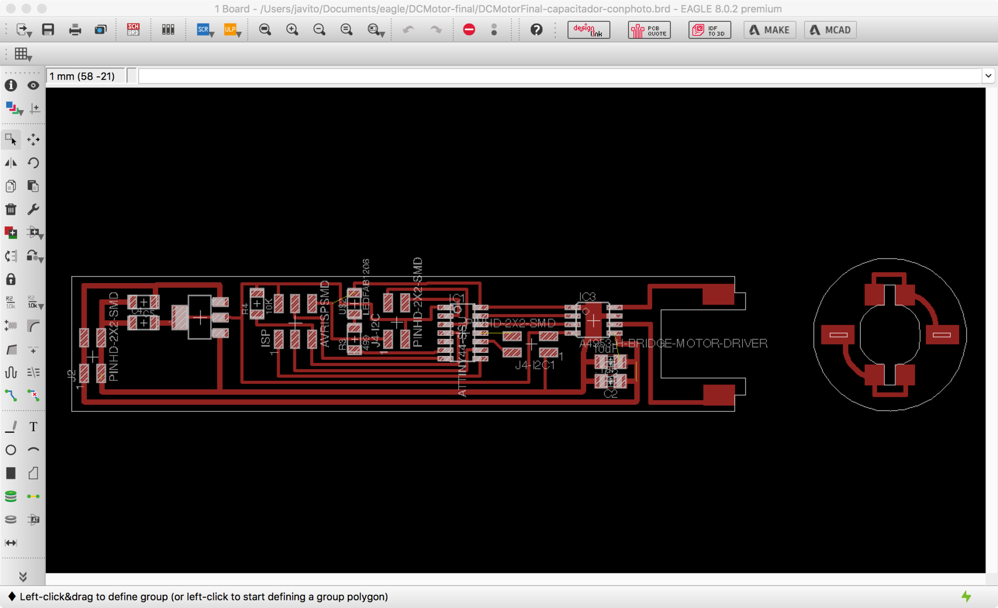
Fabrication went smoothly, milling and soldering the components was done quickly and without any problem. I really like the way everything holds together without any screws, it feels efficient and elegant. Pin connectors felt a bit tight though, I will do some research to find shorter connectors for the next iteration.
I used week 10 code to test the assembled tubular motor. Really happy to see that everything worked as expected.
Input
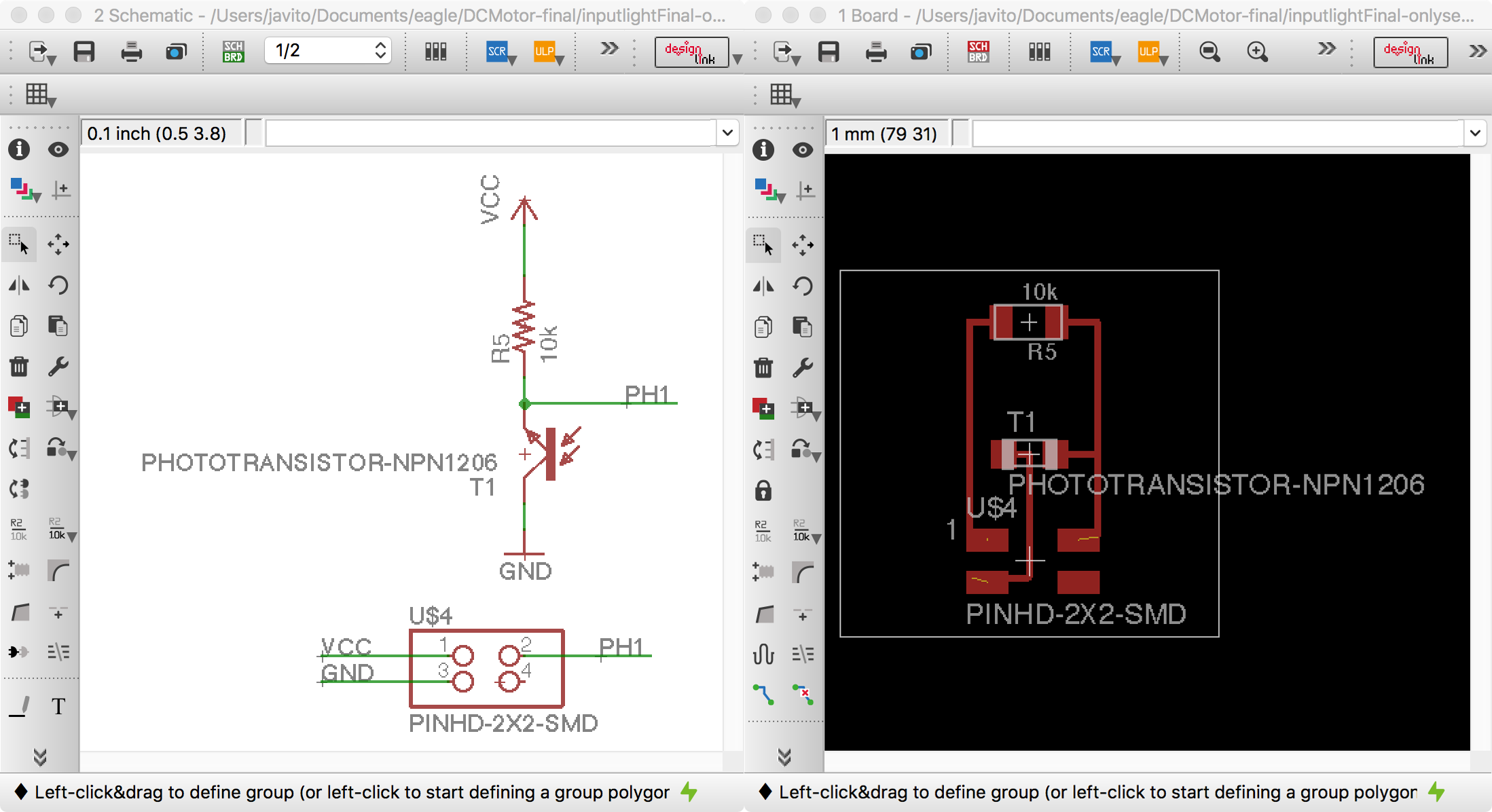
To automatically activate the blind shade I will read a IR visible phototransistor. Using the phototransistor I can sense the amount of light and activate the roller blinds if necessary. I will be using a phototransistor as the sensor, specifically the PT15-21C/TR8The device is Spectrally matched to visible and infrared emitting diode and in the datasheets they recommend to be carefully when soldering as a high temperature soldering iron tip can damage the sensor.
On week 13 I wasnt sure if the length of the cables could affect negatively to the signal to noise ratio and make the sensor unusable by itself with the possibility of having to design a second board to make the ACD conversion closer to the sensor and then send the information digitally via serial bus
After some test with 2 meter long cables I could not find noticeable noise in the sensor so I opted for the simpler solution of having just one microcontroller inside my tubular DC motor and connect the light sensor to this board directly.
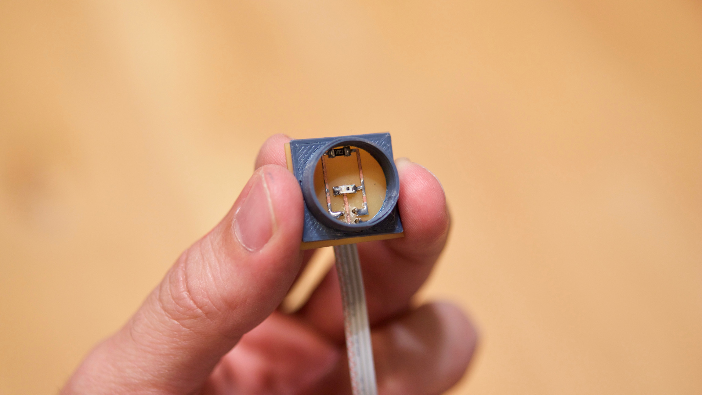
I did have to design a small board to place the sensor, resistor and connector pins. The board was also 22mm in height so I could keep certain modularity between all my electronic components. All the communication channels milled in the timber structure were 25mm width.
Finally, I merged week 10 and week 13 code into a single program to combine sensing and motor driving together. I also keept the serial bus so I can debug things easier using the computer. The functionality relies in a simple conditional and a variable that stores the information of the roller blind up and down and switch the motor in one direction or the other accordingly.
//
// fabwindow.c
// 0.1.0

#include <avr/io.h>
#include <util/delay.h>

#define output(directions,pin) (directions |= pin) // set port direction for output
#define set(port,pin) (port |= pin) // set port pin
#define clear(port,pin) (port &= (~pin)) // clear port pin
#define pin_test(pins,pin) (pins & pin) // test for port pin
#define bit_test(byte,bit) (byte & (1 << bit)) // test for bit set
#define bit_delay_time 102 // bit delay for 9600 with overhead
#define bit_delay() _delay_us(bit_delay_time) // RS232 bit delay
#define half_bit_delay() _delay_us(bit_delay_time/2) // RS232 half bit delay
#define char_delay() _delay_ms(10) // char delay
#define blind_delay() _delay_ms(10000) // char delay

#define serial_port PORTB // serial port
#define serial_direction DDRB // serial direction
#define serial_pin_out (1 << PB1)

#define led_port PORTA // led port
#define led_direction DDRA // led direction
#define led_pin_out (1 << PA7)

#define bridge_port PORTA // H-bridge port
#define bridge_direction DDRA // H-bridge direction
#define IN1 (1 << PA1) // IN1
#define IN2 (1 << PA0) // IN2

void put_char(volatile unsigned char *port, unsigned char pin, char txchar) {
  //
  // send character in txchar on port pin
  //    assumes line driver (inverts bits)
  //
  // start bit
  //
  clear(*port,pin);
  bit_delay();
  //
  // unrolled loop to write data bits
  //
  if bit_test(txchar,0)
    set(*port,pin);
  else
    clear(*port,pin);
  bit_delay();
  if bit_test(txchar,1)
    set(*port,pin);
  else
    clear(*port,pin);
  bit_delay();
  if bit_test(txchar,2)
    set(*port,pin);
  else
    clear(*port,pin);
  bit_delay();
  if bit_test(txchar,3)
    set(*port,pin);
  else
    clear(*port,pin);
  bit_delay();
  if bit_test(txchar,4)
    set(*port,pin);
  else
    clear(*port,pin);
  bit_delay();
  if bit_test(txchar,5)
    set(*port,pin);
  else
    clear(*port,pin);
  bit_delay();
  if bit_test(txchar,6)
    set(*port,pin);
  else
    clear(*port,pin);
  bit_delay();
  if bit_test(txchar,7)
    set(*port,pin);
  else
    clear(*port,pin);
  bit_delay();
  //
  // stop bit
  //
  set(*port,pin);
  bit_delay();
  //
  // char delay
  //
  bit_delay();
}
int main(void) {
  //
  // main
  //
  static char low;
  static char high;
  unsigned char blinddown=0; // false
  int sensorvalue= 0;
  //
  // set clock divider to /1
  //
  CLKPR = (1 << CLKPCE);
  CLKPR = (0 << CLKPS3) | (0 << CLKPS2) | (0 << CLKPS1) | (0 << CLKPS0);
  //
  // initialize output pins
  //
  set(serial_port, serial_pin_out);
  output(serial_direction, serial_pin_out);
  //
  output(led_direction, led_pin_out);
  //
  // initialize H-bridge pins
  //
  clear(bridge_port, IN1);
  output(bridge_direction, IN1);
  clear(bridge_port, IN2);
  output(bridge_direction, IN2);
  //
  // init A/D
  //
  ADCSRB = (0 << ADLAR); // 16.13.4 The ADLAR bit affects the presentation of the ADC conversion result in the ADC Data Register
  ADMUX = (0 << REFS1) | (0 << REFS0) // Vcc ref
    | (0 << MUX5) | (0 << MUX4) | (0 << MUX3) | (0 << MUX2) | (1 << MUX1) | (0 << MUX0); // ADC2
  ADCSRA = (1 << ADEN) | (1 << ACME) // enable
    | (1 << ADPS2) | (1 << ADPS1) | (1 << ADPS0); // prescaler /128
  //
  // main loop
  //
  while (1) {
    //
    // send framing
    //
    put_char(&serial_port, serial_pin_out, 1);
    char_delay();
    put_char(&serial_port, serial_pin_out, 2);
    char_delay();
    put_char(&serial_port, serial_pin_out, 3);
    char_delay();
    put_char(&serial_port, serial_pin_out, 4);
    char_delay();
    //
    // initiate conversion
    //
    ADCSRA |= (1 << ADSC);
    //
    // wait for completion
    //
    while (ADCSRA & (1 << ADSC));
    //
    // send result
    //
    low = ADCL;
    put_char(&serial_port, serial_pin_out, low);
    char_delay();
    high = ADCH;
    put_char(&serial_port, serial_pin_out, high);
    char_delay();
    sensorvalue = 256 * high + low;
    if(blinddown==0 && sensorvalue < 50){
      set(led_port, led_pin_out);
      // lower blind
      clear(bridge_port, IN1);
      set(bridge_port, IN2);
      _delay_ms(8500);
      // stop blind
      set(bridge_port, IN1);
      set(bridge_port, IN2);
      // Delay 2 seconds to make sure is down
      _delay_ms(2000);
      blinddown=1;
    }
    if(blinddown==1 && sensorvalue >= 50){
     clear(led_port, led_pin_out);
     // raise blind
     set(bridge_port, IN1);
     clear(bridge_port, IN2);
     _delay_ms(10000);
     // stop blind
     set(bridge_port, IN1);
     set(bridge_port, IN2);
     // Delay 2 seconds to make sure blind is down
     _delay_ms(2000);
     blinddown=0;
    }
  }
}
Interface
I decided to make an application that controls the roller blind of the window so in addition to an automated control based on the amount of light I can also control it manually.
I am very interested on the idea that each component in a house is a self-autonomous node which could sense, react and communicate with other nodes. So instead of thinking in a custom mobile app to control, I am more interested in a node running a web server with a HTML user interface and extend it with other web based technologies in the future.
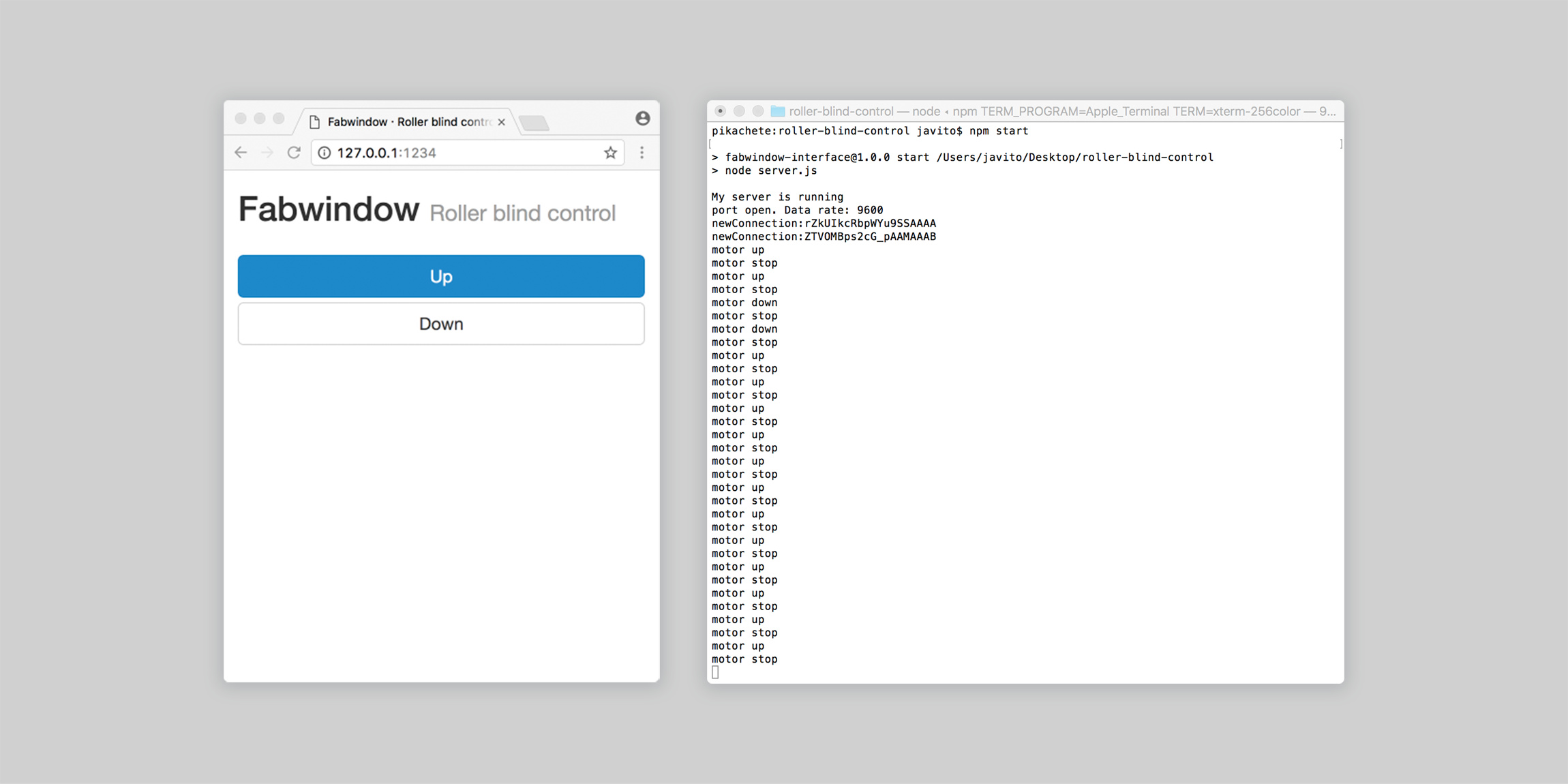
My initial solution is a JavaScript node.js server which talks to my –last week dcmotor board with input and output ports– via serial interface then a HTML form on top of bootstrap will talk to the server via websockets.
For the user interface I decided to go for the most compatible standard, HTML forms. In theory, I am able to control the window from almost any device, a screen reader or an old phone from example. In order to improve the look and feel of the buttons I choose to use bootstrap, a great framework for creating responsive HTML interfaces. You can find all the documentation here.
For the web server I use JavaScript and node.js. Node package manager for JavaScript, I am using three different elements on the webserver: Express a lightweight webframework to create web applications in node.js, Serialport, a node package to communicate with hardware via serial and Websocket a JavaScript implementation of the websocket protocol to connect my webserver with the HTML User Interface
The server's code is no more than 70 lines of code. First, it creates an express web app listening to a specific IP port, then it sets up a serial connection with our hardware device specifying the serial port address and baud rate. Third, we establish a websocket connection once the browser points to the right IP and port address and wait for the information send by the HTML form in the browser, if the information matches the intended messages we send different bytes through the serial port and the console for debugging purposes –three different messages 'u' for motor up, 'd' for motor down and 's' for motor stop–. Finally, a series of auxiliary functions send messages to the console to make sure that connection with the browser and hardware devices are occurring.
The last part would be to program the device to switch on and off the motor driver inputs and control the DC motor based on the three different commands sent via the serial port: Up, down and stop.
Then, I need to set up all the different variables and initialize the pins directions for the motor driver, led and serial connection.Inside the main loop, I check if the serial is being used, if not, it reads the data and depending on the command sent it controls the motor driver up, down or stop.
Systems integration
A good integration between all systems was an important factor during the design and fabrication process:
- Controller board was embedded inside the roller blind aluminium axis to minimize the amount of cables
- Dedicated channels and holes were created in the outer layer of the window structure so sensor and cables could be accessible, tidy and easily serviced.
And finally, this is the working prototype running the final code. Really cool!
Improvements for the next iteration:
- Adding a reverse polarity protection circuit
- Adding a control charging system so I can charge the built-in battery with small solar panels
- Include manual control developed on week 16 as part of the main program so I can switch between auto and manual modes
- Make the light value that triggers the roller blind a variable that could be changed from the webUI without reprogramming the board so it could be adjusted in different weather conditions
- Develop a limit switch system that will detect if the roller blind is the top or bottom position
- Develop a limit sensor so dc motor will stop if there are obstacles
Bill of materials
Structure and electronics
| Item | Ref | Qty | Price | Total |
|---|---|---|---|---|
| Plywood 20mm 2440x1200mm | 1 | €68,32 | €68,32 | |
| Wood glue | 19908700 | 1 | €1,70 | €1,70 |
| Wooden dowels 8x40mm package of 40 | 19586721 | 1 | €1,65 | €1,65 |
| Wood screws 4.0x45mm | TPPO40045 | 12 | €0,025 | €0,30 |
| Stainless Steel hinge. Right side | 11988522 | 2 | €3,10 | €6,20 |
| Stainless Steel hinge. Left side | 11988536 | 2 | €3,10 | €6,20 |
| Aluminium Round Tube (1000x40x1mm) | 9056K78 | 1 | €29,66 | €29,66 |
| 30% Polyester 70% PVC fabric | T5-3006 | 1 | €4,56 | €4,56 |
| Colorfab PLA Blue-grey | Blue-grey | 0,2 | €35,95 | €7,19 |
| Montó Ultra Matte varnish 500ml | 771441 | 1 | €9,50 | €9,50 |
| Total | €135,28 | |||
Note: Insulated glazing panes –aproximately €25 each pane– and gasket seals were not included on this prototype for budget reasons. Insulated glass can be acquired at local vendors, in my case this one, easily and Resinastermoplasticas is a spanish vendor for the second one.
| Item | Ref | Qty | Unit Price | Price |
|---|---|---|---|---|
| Dooya Tubular DC motor | TM25LE | 1 | €71,50 | €71,50 |
| Resistance 499K 1-4W SMD | 311-10.0KFRCT-ND | 2 | €0,01 | €0,02 |
| Resistance 499K 1-4W SMD | 311-499KFRCT-ND | 2 | €0,01 | €0,02 |
| Capacitor ceramic .1PF SMD | 399-4674-1-ND | 1 | €0,12 | €0,12 |
| Capacitor ceramic 10PF SMD | 311-1150-1-ND | 1 | €0,04 | €0,04 |
| Capacitor ceramic 22PF SMD | 99-8165-1-ND | 2 | €0,02 | €0,04 |
| LED green 1206 SMD | 160-1169-1-ND | 1 | €0,15 | €0,15 |
| Regulator 5V 1A SOT223-3 | ZLDO1117G50DICT-ND | 1 | €0,34 | €0,34 |
| PWM Motor driver 8SOIC | 620-1428-1-ND | 1 | €1,57 | €1,57 |
| Attiny44 14SOIC | ATTINY44A-SSU-ND | 1 | €1,18 | €1,18 |
| Phototransistor 940nm visible SMD | 1080-1380-1-ND | 1 | €0,15 | €0,15 |
| 4 Header Connector 2.54mm SMD | 609-5160-1-ND | 4 | €0,66 | €2,64 |
| 6 Header Connector 2.54mm SMD | 609-5161-1-ND | 1 | €0,60 | €0,60 |
| Total | €78,37 | |||
Note: I purchased the Dooya tubular motor and made my own custom board. DC motor, gearbox and battery could be purchased separately and then use a 25mm diameter steel tube and 3D printed connectors ends. I will explore this possibility in the next iteration of the prototype.
Analisys
What does it do?
Fabwindow is a 3 axis CNC compatible design for high performance timber windows up to Eurocode standards. The design is fully parametric allowing extensive customization and adaptability to different glazing systems, seals and stock timber. The design has an integrated I/O approach so multiple sensors and actuators can be integrated into the frame. This first prototype has a light activated exterior roller blind to protect the glass from excessive sunligth exposure.
Who's done what beforehand?
I couldn't find further information on FablabBCN's fab lab house windows. Still unsure if they are CNC made or not.
The MIT house for New Orleans was focused on the main structure and facade details, there are a number of windows on the project but from online literature and images is difficult to determine how they were build.
Wikihouse has developed an interior door design but not windows
Facit homes creates CNC cut structural systems but not windows
What did you design?
- Window complete structure
- Roller blind side holders
- Microcontroller board for DC motor
- DC tubular motor caps and rings
- Phototransistor sensor board
- Microcontroller software
- Web application for roller blind direct control
What materials and components were used?
All the materials and components are described in the BOM avobe
Where did they come from?
Most of the elements came from fab lab inventory. The ones not included are:
- DC motor, gear box and steel tube. On week 10 I purchased an integrated solution from China for analysis. I have reused DC motor, gear box and steel tube from this solution. The reason for purchasing this solution was to be able to understand how these systems are designed.
- Aluminium tube 40mm diameter and 1.2mm wall thickness, purchased locally
- Blind fabric 30% polyester 70% PVC, purchased locally
- Double glazing, not purchased at the end for budget reasons –each pane cost €25–
- Gasket seals, not purchased at the end for budget reasons
How much did they cost?
Detailed cost on the BOM above. The total cost of the prototype is €210, raising to €270 if glazing and rubber seals were included.
Please note that for budget restriction issues –I was not allowed to use more than one single sheet of ply for this prototype and my initial dimensions would have required two– I have to do a reduced version of the window 1000mm by 1200mm instead of 1200mm by 1600mm so I wont be able to install the window in my own house to do further real world testing.
What parts and systems were made?
- Window structure
- Roller blind mechanical system
- Roller blind motor system
- light sensor system
What processes were used?
- CNC for window structure
- 3D printing for roller blind caps and holders
- PBC milling for all boards
What questions were answered?
- Is the design fully parametric? Yes it is, adapting to different stock thicknesses, glass thickness and general dimensions is an almost instant process. Getting the 3D parametric file into CNC ready file is more time-consuming, I will be researching on more streamlined methods to do this.
- Is the fabwindow structure as sound as a traditional timber window? I havent done scientific load test yet but initial perception is that the construction method is as good as a traditional one. Plywood might bring an additional dimensional stability too.
- Does the design comply Eurocode standards? I wont be able to test the window in a real work scenario due to budget issues so It will be harder to test sound proof and weatherproof capabilities.
- Is the light sensor reliable enough to sense direct sunlight exposure as opposed to ambient light? I found that 10 bit ACD conversion gives enough resolution. On daylight the sensor is not saturated so it would be able to work fine in most weather conditions. During the last weeks I have found other sensors that can mimic the high dynamic range of the human eye more precisely.
- Can the DC motor controller and battery be safely integrated within the roller tube? Yes, this provide a weatherproof and compact package that allows to integrate the roller blind into the window structure itself.
How was it evaluated?
I have not been able to install the window in my own house due to budget restrictions so my evaluation plan is greatly affected now. This prototype proves that it is possible to fabricate and assembly robust and durable windows in a fab lab compatible way. Real world tests are needed in order to push the project further.
what are the implications?
The success of the prototype has encouraged me to attempt a second prototype. I will address some fabrication issues as labelling and auto alignment for squaring the structure. On the electronics side I need to integrate the manual and auto light mode as well as developing a charging circuit so the built-in battery can be charged using small solar panels embedded on the frame.
License
All text and photos are licensed by Javi BuronGarcia under a CC BY-NC-ND license. All design files are copyrighted by Javi BuronGarcía ©2107.
I would like to thank my partner Magda for her continuos and restless support during these five intense months, my daugther Magda for inspiring my best designs and being such a cute model in my photos and my fellow students at Fab Lab Madrid CEU for their help.
Files
design and fabrication files
- CNC
- 3D printing
- Boards