Fabacademy 2017
Thirteenth Week. Input devices
Index
Thirteenth task
Input
This week task is to add a sensor to a microcontroller board that you have designed and read it. I will use this week task to work on my final project and read a IR visible phototransistor. I will research the two applications explained at the class. First, using the phototransistor so I can sense the amount of light and activate the roller blinds if necessary. Second, use the light reflect technique so I could potentially use the same phototransistor as end stop switches for the roller blind
I will be using a phototransistor as the sensor, specifically the PT15-21C/TR8The device is Spectrally matched to visible and infrared emitting diode and in the datasheets they recommend to be carefully when soldering as a high temperature soldering iron tip can damage the sensor.
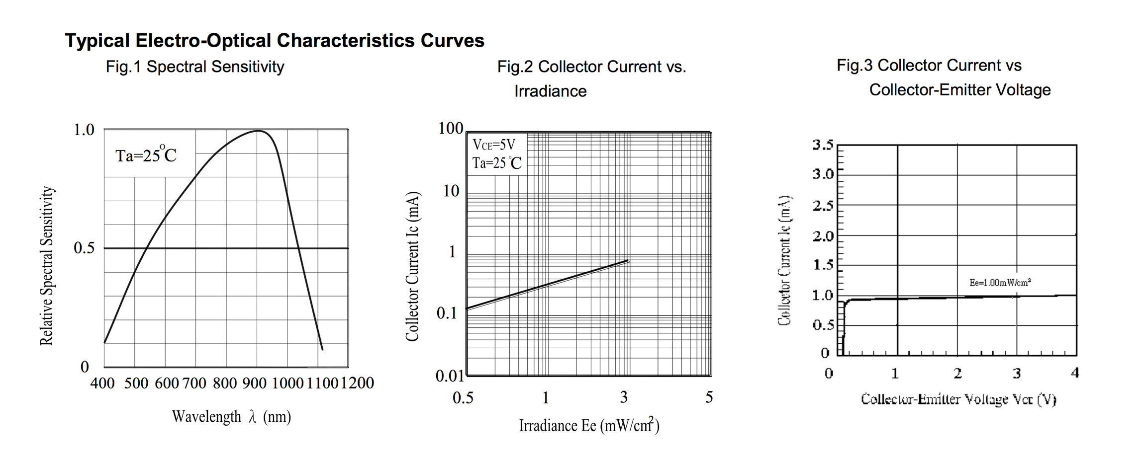
Afer doing some research on ambient light sensors, I am still not sure if the PT15-21C/TR8 will be the right one for the first applications that I have in mind –sensing if there is too much sun radiation so I can roll down the blinds– In this article some of the characteristics of these type of sensors are explained. These sensors have experienced an intense development as they are key components to adjust brightness of mobile devices in exterior environments. These sensors try to mimic the spectral sensitivity of the human eye.
Designing the board
As I would need to do several different test, this week I decided to do a board with more potential functionality than previous weeks. I based my board on hello.reflect.45 but adapted to use a ATtiny44 instead of the ATtinty45 so I can have additional pins for testing out different sensors configurations. I also decided to add a 20MHz crystal in case I want to improve the clock precision of the board when transmitting data via the FTDI port.
I also added a 4 pin external connector to attach a remote phototransistor sensor. In this way, I will be able to measure the signal noise caused by long cables when sensing the ambient light at different points of the window.
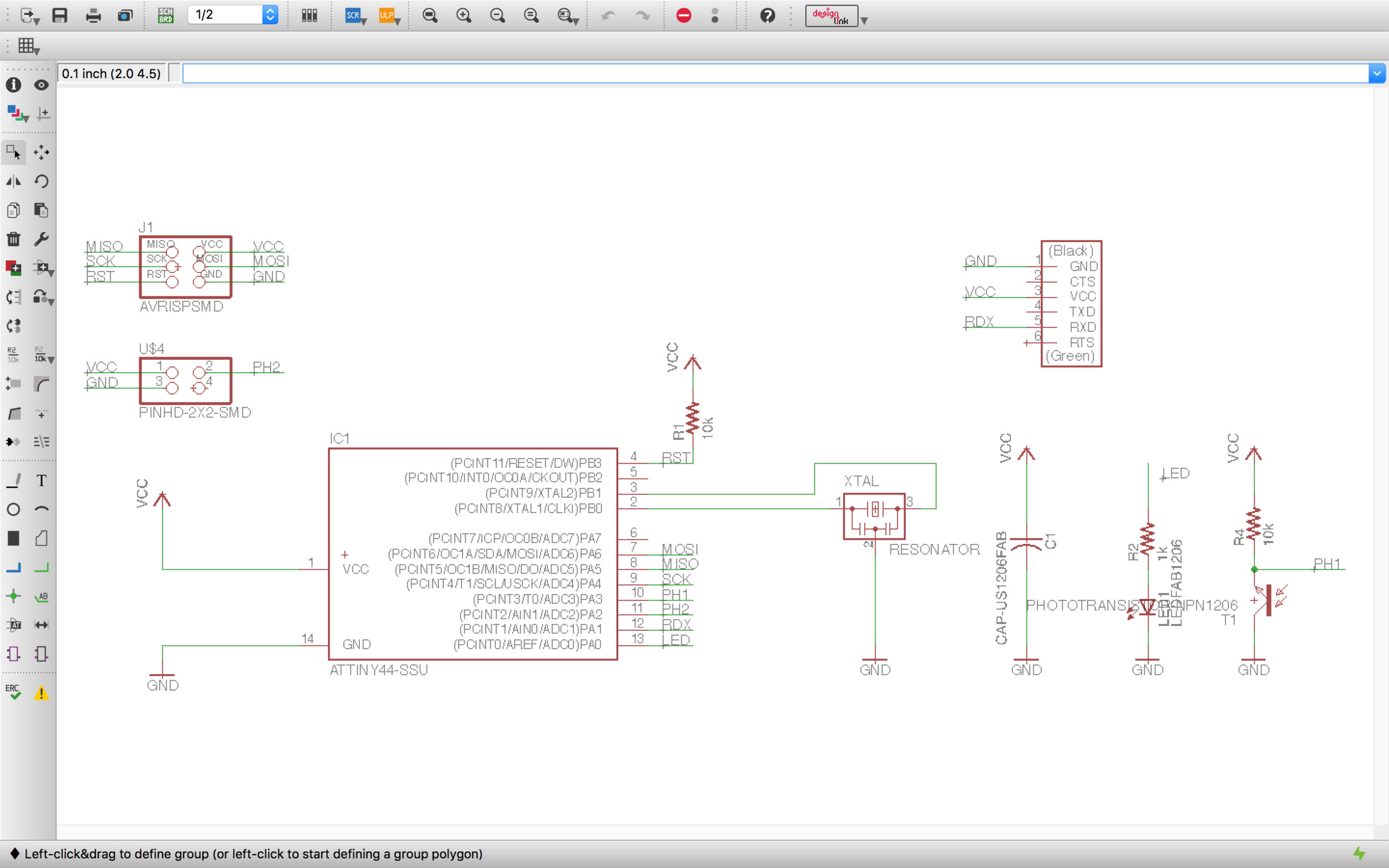
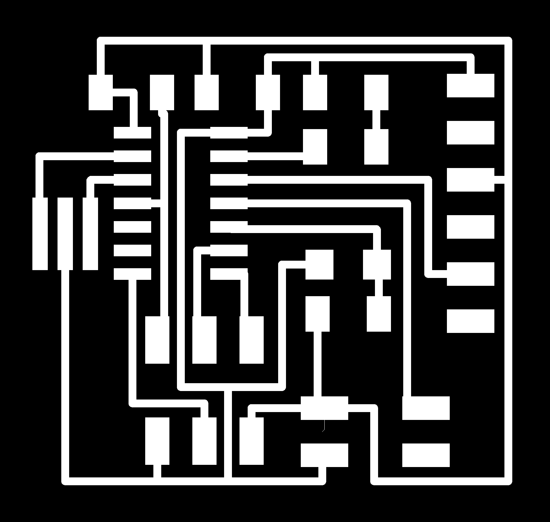
Once the schematic is ready is time for the board design. Having to design new boards each week is great for getting comfortable with this process. As more pins are used and new boards have more components and functionality the design becomes harder.
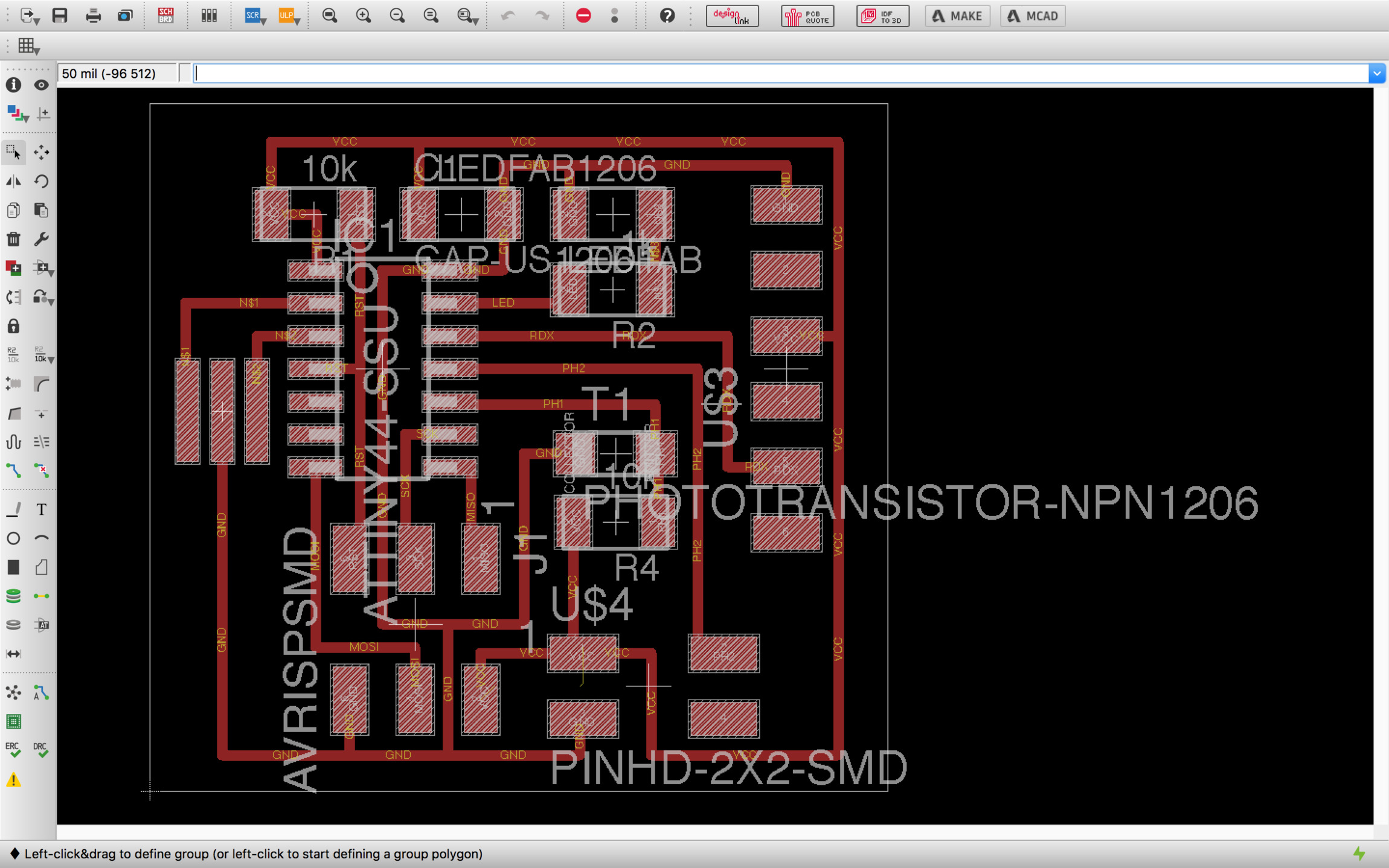
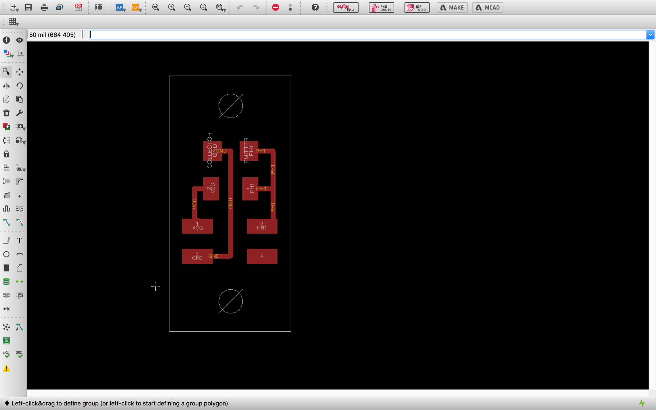
As said before, I decided to make an auxiliary board which will work as a remote phototransistor sensor for testing purposes. If the signal noise ratio is not acceptable I will have to include a microprocessor on each sensor board, do the analog to digital conversion near the sensor and transmit the readings digitally.
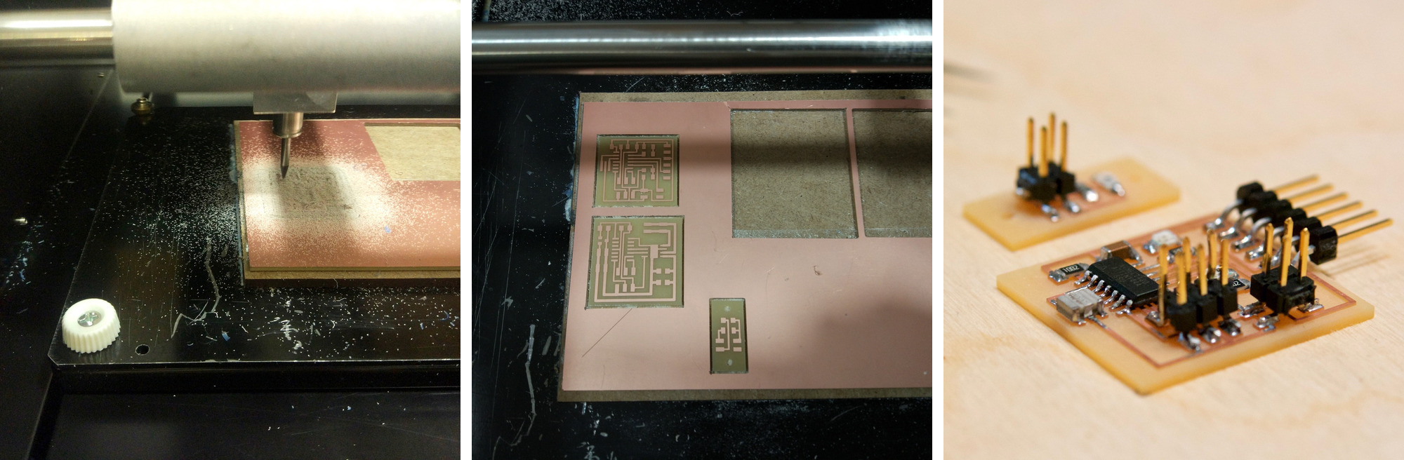
Fabricating the board
The fabrication process went without much problems. Cutting both boards and soldering all the components was a smooth an increasingly enjoyable process.
Programming and testing
ATtiny44 analog digital converter
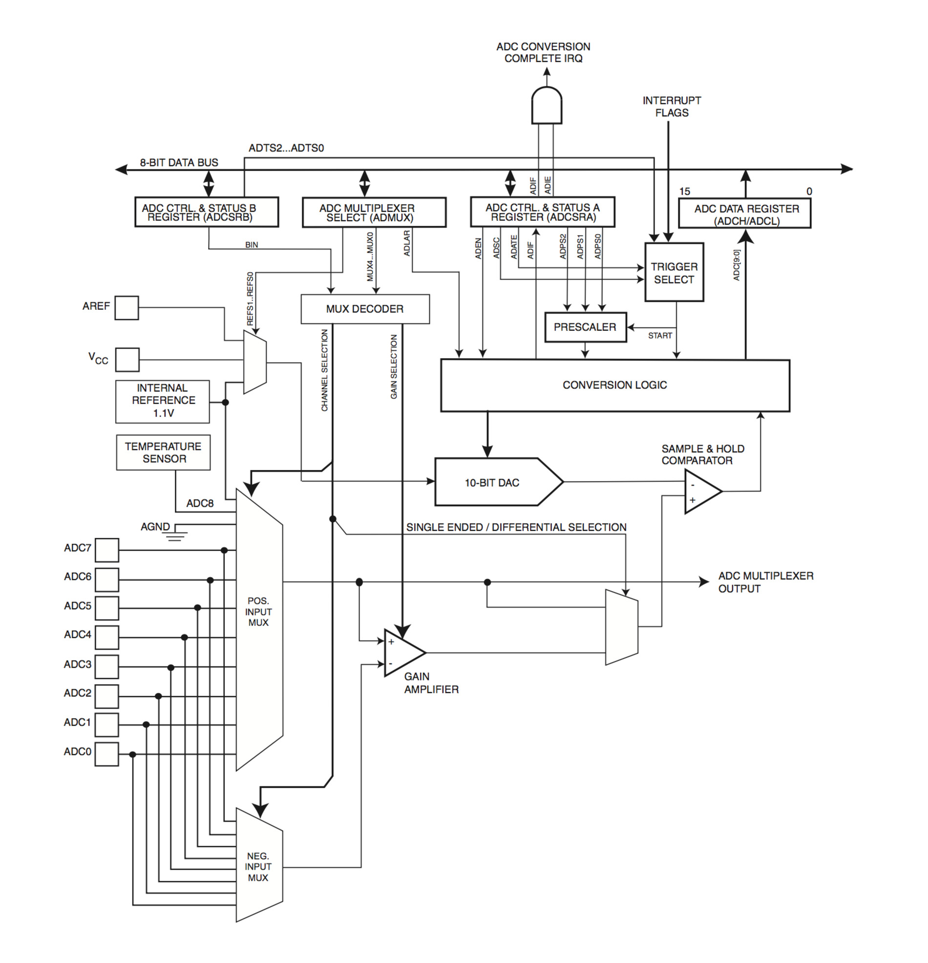
The analog digital converter converts an analog voltage to a 10-bit digital value. The minimun voltage represents GND and the maximun value represents the reference voltage. We can select between three different voltages by writing to the REFS1 and REFS0 bits in the ADMUX registry: internal 1.1v, VCC supply or use the AREF pin. The analog input channel are selected by writing to the MUX5:0 bits in ADMUX. The ADC can also be used for differential measurements
The ADC generates a 10-bit result which is presented in the ADC Data Registers, ADCH and ADCL. If the result is left adjusted and no more than 8-bit precision is required, it is sufficient to read ADCH. A single conversion is started by writing a logical one to the ADC Start Conversion bit, ADSC. This bit stays 1 as long as the conversion is in progress and will be cleared by hardware when the conversion is completed.
I will be programming first the proximity sensing feature using the synchronous detection technique. The principle is that you get a number of samples from the light sensor switching on and off an adjacent led so you get a modulated signal on top of the analog signal, by doing this you can measure the relative amount of light with significant precision. I am using hello.reflect.45.c as the reference, commented code below:
//
// week13-inputlight.44.c
//
#include <avr/io.h>
#include <util/delay.h>

#define output(directions,pin) (directions |= pin) // set port direction for output
#define set(port,pin) (port |= pin) // set port pin
#define clear(port,pin) (port &= (~pin)) // clear port pin

#define pin_test(pins,pin) (pins & pin) // test for port pin
#define bit_test(byte,bit) (byte & (1 << bit)) // test for bit set

#define bit_delay_time 102 // bit delay for 9600 with overhead
#define bit_delay() _delay_us(bit_delay_time) // RS232 bit delay
#define half_bit_delay() _delay_us(bit_delay_time/2) // RS232 half bit delay
#define char_delay() _delay_ms(10) // char delay

#define serial_port PORTA    // RS232 serial output
#define serial_direction DDRA
#define serial_pin_out (1 << PA1)

#define led_port PORTA     // led output
#define led_direction DDRA
#define led_pin (1 << PA0)

#define nloop 100 // number of loops to accumulate

void put_char(volatile unsigned char *port, unsigned char pin, char txchar) {
   //
   // send character in txchar on port pin assumes line driver (inverts bits)
   //
   // start bit
   // port, *port = contenido address = serial_port
   clear(*port,pin);
   bit_delay();
   //
   // unrolled loop to write data bits
   // Con Bit_test comprueba para cada bit del byte txchar 0,1,2...7
   // if equal to 1 then SET otherwise CLEAR
   if bit_test(txchar,0)
      set(*port,pin);
   else
      clear(*port,pin);
   bit_delay();
   if bit_test(txchar,1)
      set(*port,pin);
   else
      clear(*port,pin);
   bit_delay();
   if bit_test(txchar,2)
      set(*port,pin);
   else
      clear(*port,pin);
   bit_delay();
   if bit_test(txchar,3)
      set(*port,pin);
   else
      clear(*port,pin);
   bit_delay();
   if bit_test(txchar,4)
      set(*port,pin);
   else
      clear(*port,pin);
   bit_delay();
   if bit_test(txchar,5)
      set(*port,pin);
   else
      clear(*port,pin);
   bit_delay();
   if bit_test(txchar,6)
      set(*port,pin);
   else
      clear(*port,pin);
   bit_delay();
   if bit_test(txchar,7)
      set(*port,pin);
   else
      clear(*port,pin);
   bit_delay();
   //
   // stop bit
   //
   set(*port,pin);
   bit_delay();
   //
   // char delay
   //
   bit_delay();
   }

int main(void) {
   //
   // main
   //
   static unsigned char count;
   static uint16_t on,off;
   //
   // set clock divider to /1
   //
   CLKPR = (1 << CLKPCE);
   CLKPR = (0 << CLKPS3) | (0 << CLKPS2) | (0 << CLKPS1) | (0 << CLKPS0);
   //
   // initialize output SERIAL and output LED pins
   //
   set(serial_port, serial_pin_out);
   output(serial_direction, serial_pin_out);

   set(led_port, led_pin);
   output(led_direction, led_pin);
   //
   // init A/D
   // ADC Analog Digital Converter
   // ADMUX – ADC Multiplexer Selection Register
   ADCSRB = (0 << ADLAR); // 16.13.4 The ADLAR bit affects the presentation of the ADC conversion result in the ADC Data Register
   ADMUX = (0 << REFS1) | (0 << REFS0) // 16.13.1 VCC used as Voltage Reference
      | (0 << MUX4) | (0 << MUX3) | (0 << MUX2) | (1 << MUX1) | (1 << MUX0); // Table 15.1 The value of these bits selects which combination of analog inputs are connected to the ADC 00011 = ADC3
   // – ADC Control and Status Register A
   ADCSRA = (1 << ADEN) | (1 << ACME) // enable (Writing this bit to one enables the ADC)
      | (1 << ADPS2) | (1 << ADPS1) | (1 << ADPS0); //  ADPS[2:0]: ADC Prescaler Select Bits: prescaler /128
      // These bits determine the division factor between the system clock
      // frequency and the input clock to the ADC
   //
   // main loop
   //
   while (1) {
      //
      // accumulate
      //
      on = 0;
      off = 0;
      for (count = 0; count < nloop; ++count) {
         //
         // LED off
         //
         clear(led_port, led_pin);
         //
         // initiate analog to digital conversion
         //
         ADCSRA |= (1 << ADSC); // 16.4 Start Conversion
                                // Register ADCSRA: ADC Control and Status Register A
                                // Bit ADSC: ADC Start Conversion,
                                // In Single Conversion mode, write this bit to one to start each conversion.
         // wait for completion: ADSC will read as one as long as a conversion is in progress.
         // When the conversion is complete, it returns to zero.
         // Writing zero to this bit has no effect.
         //
         while (ADCSRA & (1 << ADSC));
         //
         // save result
         //
         off += ADC;
         //
         // LED on
         //
         set(led_port, led_pin);
         //
         // initiate conversion
         //
         ADCSRA |= (1 << ADSC);
         //
         // wait for completion
         //
         while (ADCSRA & (1 << ADSC))
            ;
         //
         // save result
         //
         on += ADC; // on = on + ADC
         }
      //
      // send framing
      //
      put_char(&serial_port, serial_pin_out, 1);
      char_delay();
      put_char(&serial_port, serial_pin_out, 2);
      char_delay();
      put_char(&serial_port, serial_pin_out, 3);
      char_delay();
      put_char(&serial_port, serial_pin_out, 4);
      char_delay();
      //
      // send result
      //
      put_char(&serial_port, serial_pin_out, (on & 255)); // toma el LSB (least significant byte) 0b1111 1111
      char_delay();
      put_char(&serial_port, serial_pin_out, ((on >> 8) & 255)); // toma el MSB
      char_delay();
      put_char(&serial_port, serial_pin_out, (off & 255));
      char_delay();
      put_char(&serial_port, serial_pin_out, ((off >> 8) & 255));
      char_delay();
      }
   }
Porting from ATtiny45 to ATtiny44 requires further study of ATtiny44 datasheets, specifically chapter 16 for the Analog to Digital Converter and its multiplexed input.
First part of the code some macros are created for assigning bit on specific pins, number of sampling cycles, and four different delays to make sure that serial communication is sent at the right speed
Then the put_char function is created, this will send the ADC digital signal as a 8-bit byte through the serial port. This function uses a coding feature that I didn't know called Pointers, this allow the function to get the value stored in memory address of the serial port without the need of creating a global variable.
Inside the main loop, first we set the clock resolution, then we initialize the output pins for the serial interface and the led. After that, we initialize the Analog to Digital Converter Multiplexer which is a device to select one of several inputs and forward the selected input to a single line. The multiplexeer is different in the ATtinty45 and ATtiny44 so it is important to read carefully sections 16.13.1 and 16.13.4 and table 15.1 to assign the right bit to the ADMUX register
Finally, in the main loop is where the magic happens. A loop of 100 cycles is created, we switch on the led, starts the ADC conversion, wait until the conversion is done and stores the value on a variable, then we switch off the led and repeat the process. The results are being Oversampled by adding then in each cycle, this helps to reduce the noise to signal ratio. Lastly, the 100 samples of "on" and "off" values are taken, we send the signal via serial to the computer. It is worth mentioning that as we are oversampling the signal we would need to transmit 16-bit byte, this is done at the end of the code by splitting the value into two 8-bit bytes and send one after the other.
The python script receives the data from the serial port and plots it. I just took the original python script from the example. There is a header data signal –1,2,3,4– to tell the python script to read the data right after that using the 8-bit packets approach described.
Below is a video in which you can watch the sensor in action. As soon as the finger approximates to the sensor the differential value between the on and off states spikes. If I have more time in the following weeks I would like to explore other configurations like using the board as just an ambient light sensor, measuring potential noise of the remote sensor and giving a try to the ADC comparator module of the ATtiny.