Fabacademy 2017
Fifteenth Week. Networking and communications
Index
Fifteenth task
Build a network with two or more microprocessors
This week tasks was to design and build a wired &/or wireless network connecting at least two processors. In my final project I will have at least two separate boards, first the controller of the tubular DC motor installed inside the blind roller itself and second my light sensing board at the bottom of the window. In order to minimize noise, I decided to perform the analog to digital conversion as close to the sensor as possible and transmit a digital signal via a network instead of an analog one.
A potential third board would act as a master node to control input and output boards but I still not decided about that so for this week I would just try to create a simple network and then expand functionality as I learn more about how to communicate several micro micro controllers.
I2C bus specification
Inter-IC or I2C-bus is a simple bidirectional 2-wire bus for inter-IC control. The Specification manual describes in detail how the bus works. Only two bus lines are required: a serial data line (SDA) and a serial clock line (SCL). Each device connected to the bus is software addressable by a unique address and simple master/slave relationships exist at all times; masters can operate as master-transmitters or as master-receivers.
Attiny44 includes an USI – Universal Serial Interface –information located on the section 14 of the datasheet–. The USI provides the basic hardware resources needed for serial communication. The USI allows significantly higher transfer rates and uses less code space than solutions based on software only.
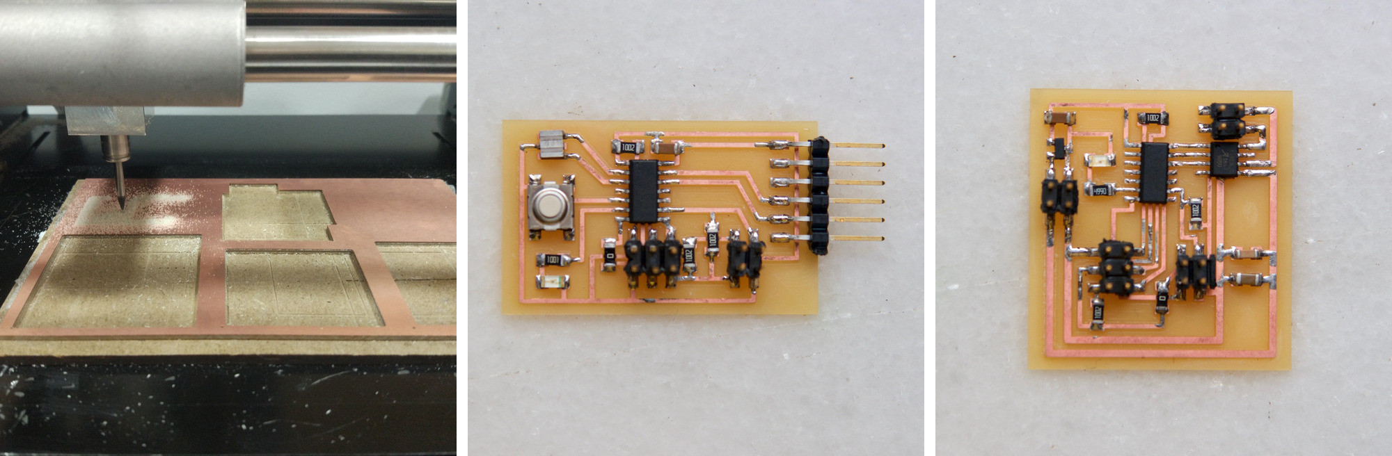
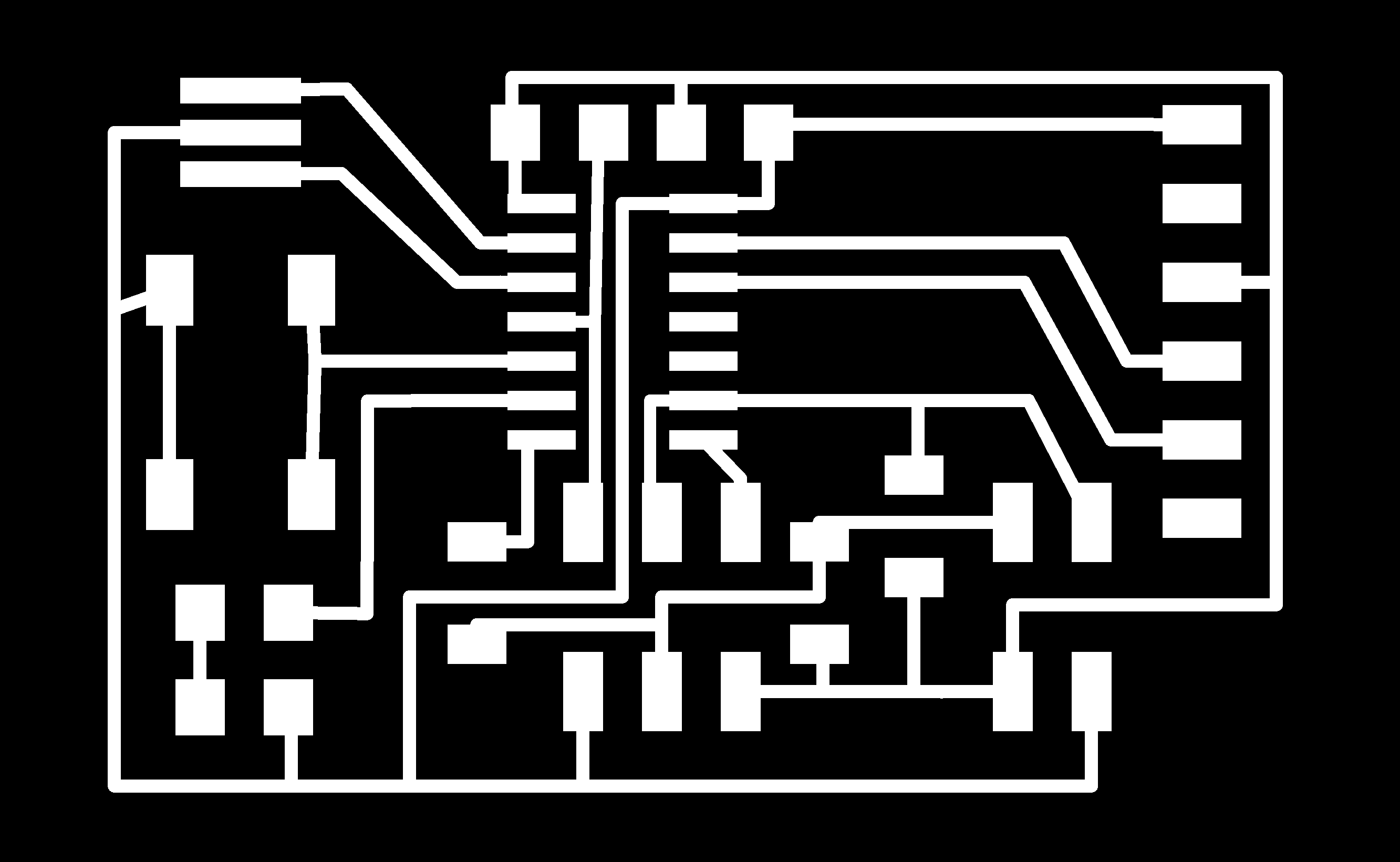
Designing the boards
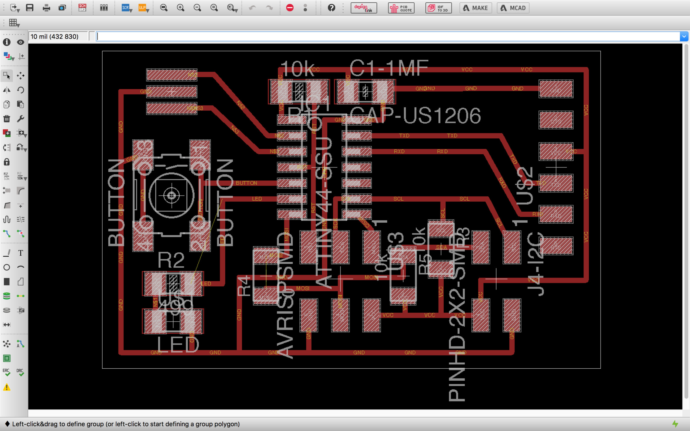
My first board is based on week 8 exercise. I decided to adapt this board to make it I2C compatible. As it was explained on class I2C is only necessary if we are going to network with other I2C devices and in my case in principle it wont be necessary. I decided to make a I2C compatible board anyway so I can learn more about this 2-wire bus protocol.
In order to use the USI you need to assign the correct pins. In the case of ATtiny44. SLC will use the same pin than SCK which is the PA4 and SDA the same than MOSI which is the PA6. I also added a 20Mhz crystal in case I want to increase the serial speed and I need more precision than the internal clock can provide.
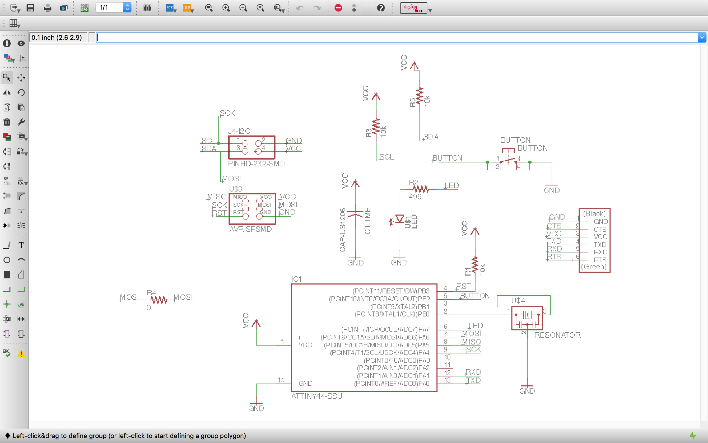
I found this board much more difficult than the others as it needs specific PINs locations in different systems –USI, in chip programmer and crystal. It was the first time I had to use zero Ohm resistances as Zero Ohm Links. I used two in this board, I will try to reduce the number of them for my final boards.
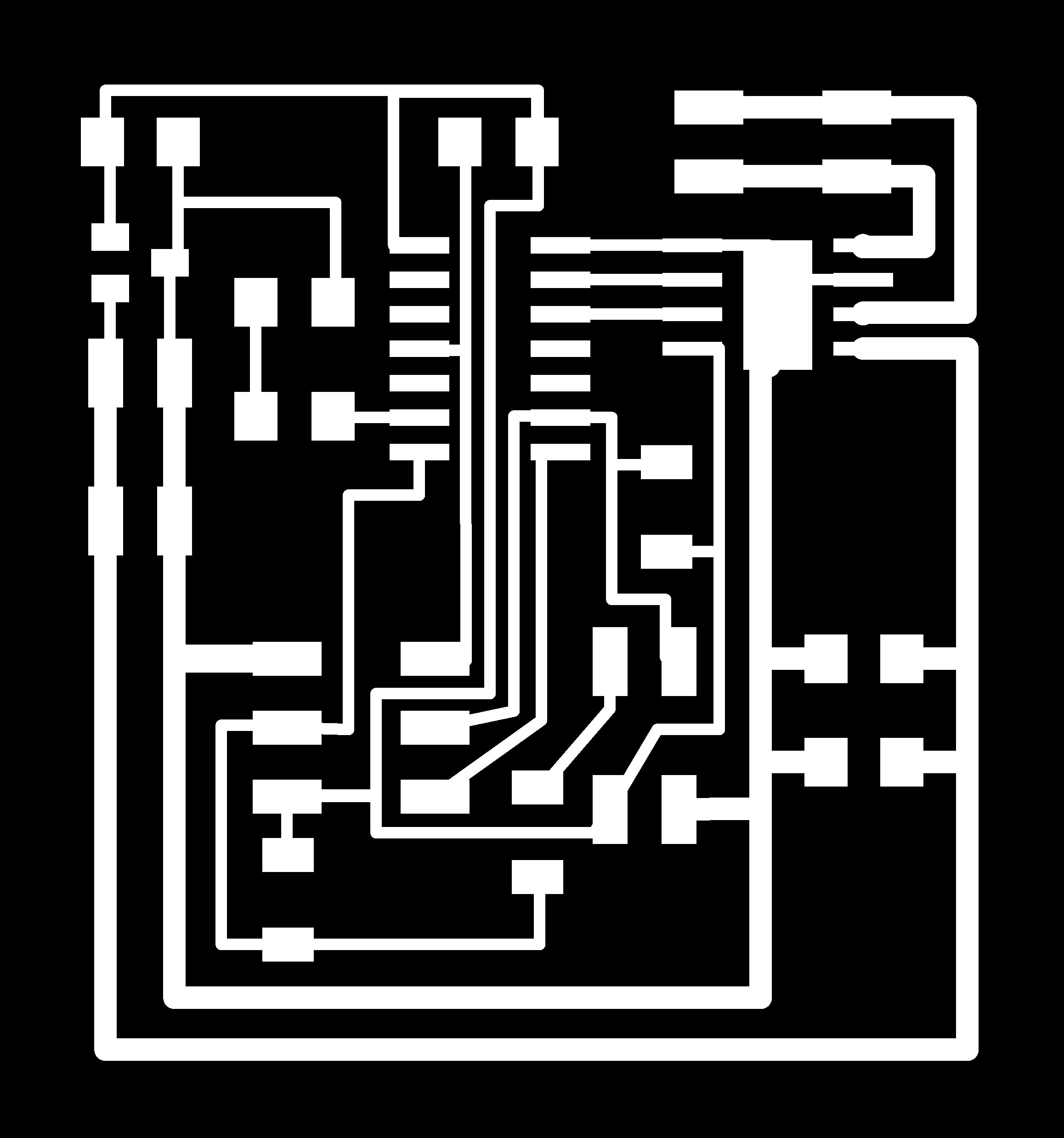
The second board was a modified version of my DC output board made on Week10. additionally, I added a I2C compatible port and a led for feedback purposes.
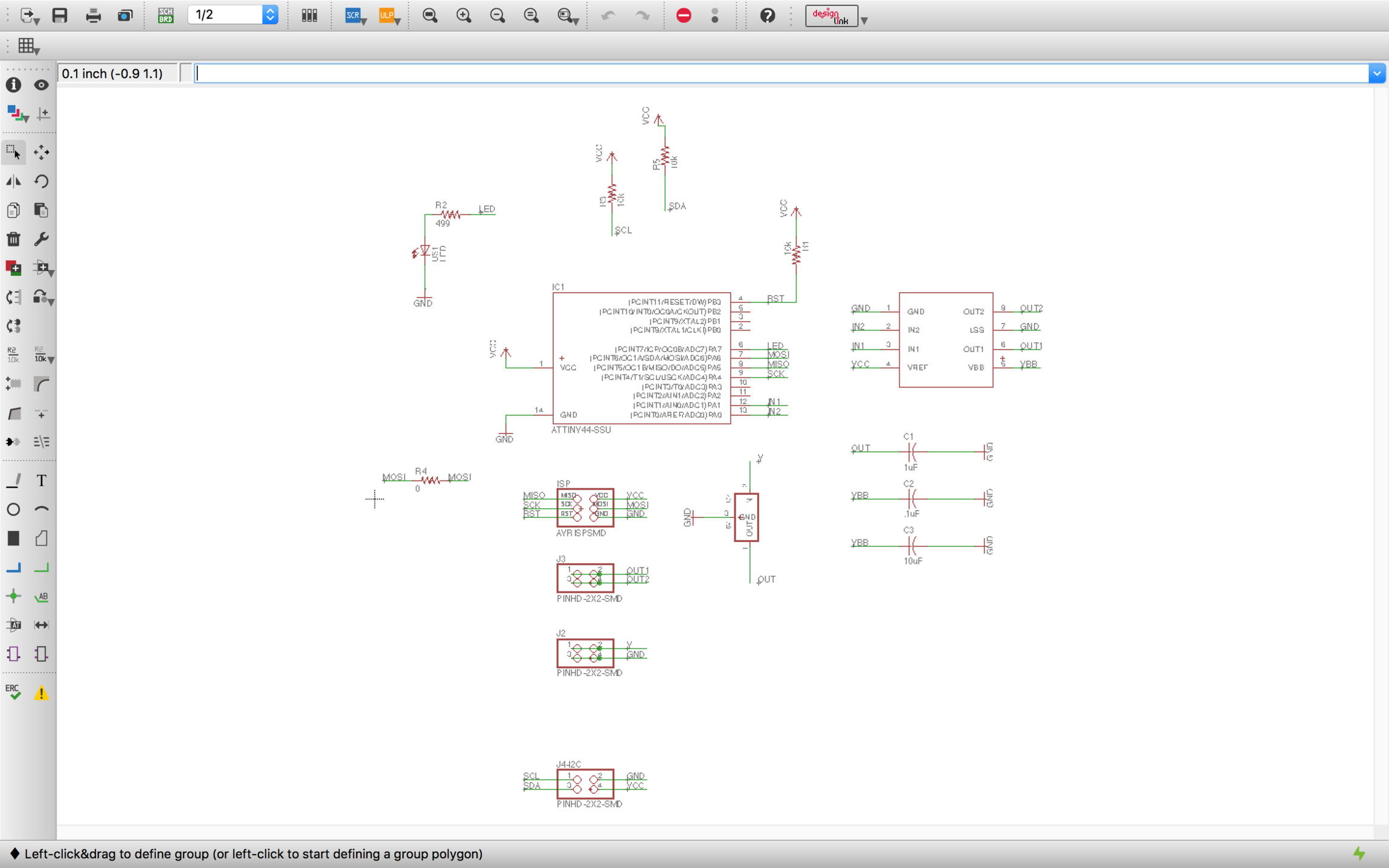
Similar than the first one, it took me longer to design the board and have to use one zero ohm link.
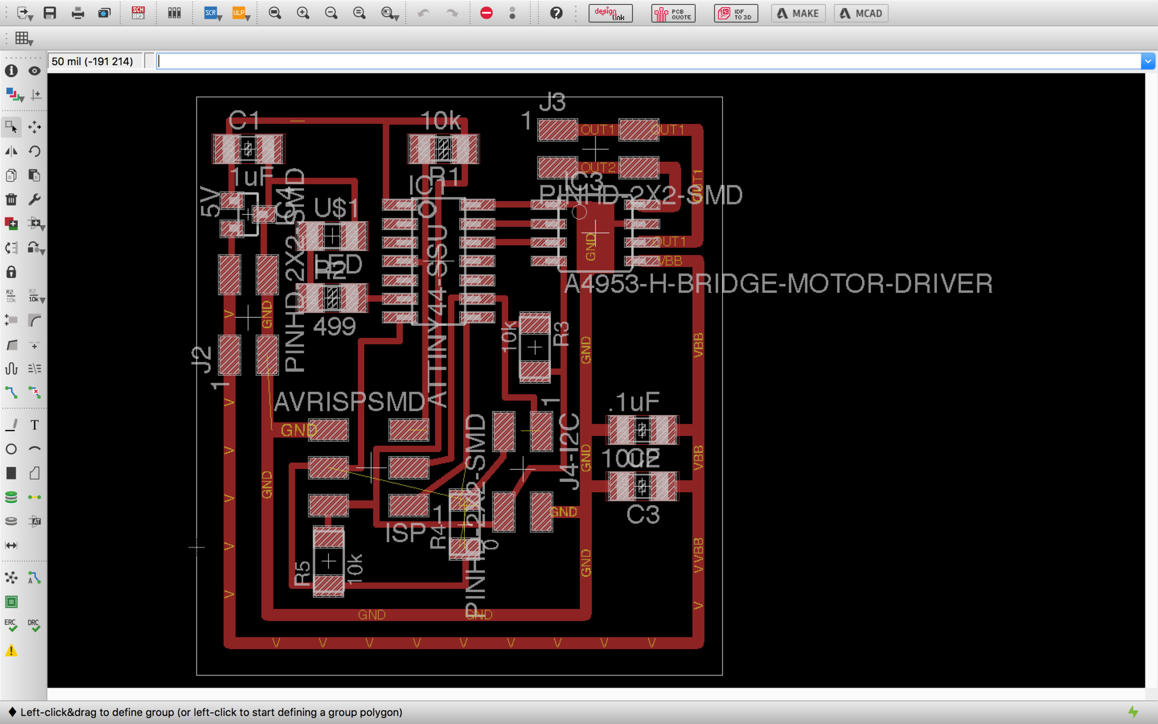
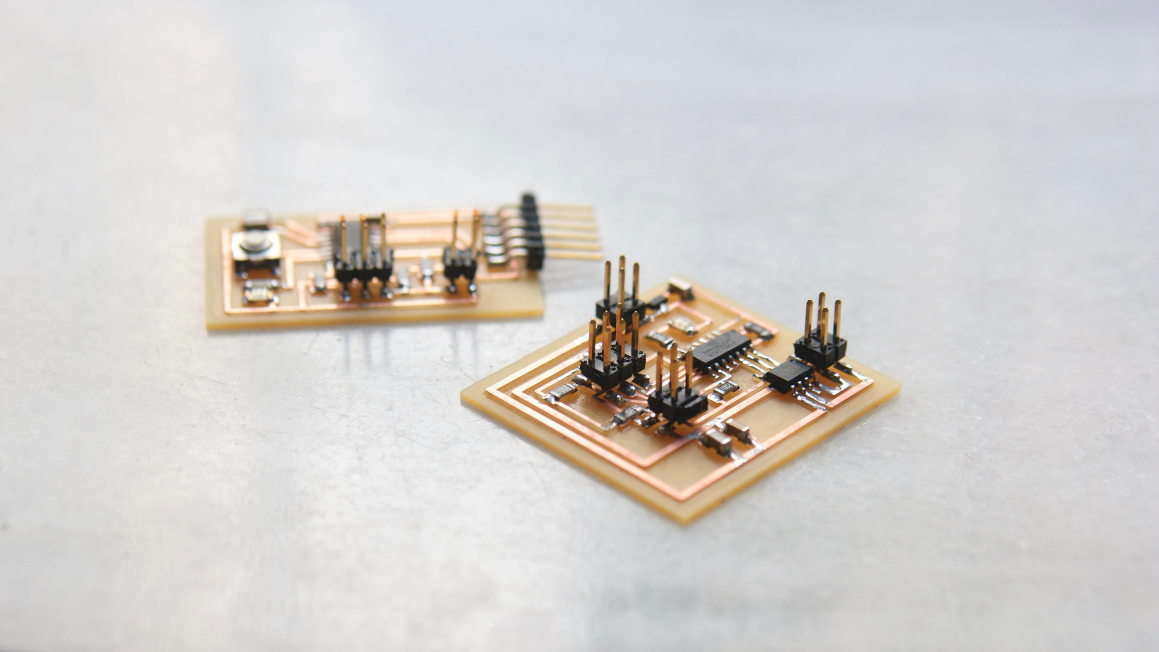
Fabrication
Fabrication and soldering went well with no major hiccups. I realized that I am including some components that I might not use in this week task making the board more complex –and expensive– than necessary but I hope this will give me more flexibility to test multiple codes and functionality while I'm working on the boards for my final project.
Programming and testing
I will be using C for programming this board. The initial functionality would be. The master board has a button so when the button is pressed I write a value in a variable and I send this value using the serial port. The slave board will be waiting for this value and will switch on a Led when this happens.
My initial intentions were to use I2C for the communication between microprocessors but after reading the I2C specification and realizing that it was more difficult than I expected I decided to implement a simple serial bus communication for the moment. Find the code commented below.
#include <avr/io.h>
#include <util/delay.h>
#include <avr/pgmspace.h>
#include <string.h>

#define output(directions,pin) (directions |= pin) // set port direction for output
#define input(directions,pin) (directions &= (~pin)) // set port direction for input
#define set(port,pin) (port |= pin) // set port pin
#define clear(port,pin) (port &= (~pin)) // clear port pin
#define pin_test(pins,pin) (pins & pin) // test for port pin
#define bit_test(byte,bit) (byte & (1 << bit)) // test for bit set
#define bit_delay_time 100 // bit delay for 9600 with overhead
#define bit_delay() _delay_us(bit_delay_time) // RS232 bit delay
#define half_bit_delay() _delay_us(bit_delay_time/2) // RS232 half bit delay
#define led_delay() _delay_ms(100) // LED flash delay

// button port in MASTER PB2
#define input_port PORTB
#define input_direction DDRB
#define input_pin (1 << PB2)
#define input_pins PINB

// led port in SLAVE PA7
#define led_port PORTA
#define led_direction DDRA
#define led_pout (1 << PA7)

// SLC - SCK - PA4 - PIN_IN
// SDA - MOSI - PA6 - PIN_OUT
#define serial_port PORTA
#define serial_direction DDRA
#define serial_pins PINA
#define serial_pin_scl (1 << PA3)
#define serial_pin_sda (1 << PA2)

// MASTER - BUTTON - ID 0
// SLAVE - LED - ID 1
#define node_id 0

void get_char(volatile unsigned char *pins, unsigned char pin, char *rxbyte) {
   //
   // read character into rxbyte on pins pin
   //    assumes line driver (inverts bits)
   //
   *rxbyte = 0;
   while (pin_test(*pins,pin))
      //
      // wait for start bit
      //
      ;
   //
   // delay to middle of first data bit
   //
   half_bit_delay();
   bit_delay();
   //
   // unrolled loop to read data bits
   //
   if pin_test(*pins,pin)
      *rxbyte |= (1 << 0);
   else
      *rxbyte |= (0 << 0);
   bit_delay();
   if pin_test(*pins,pin)
      *rxbyte |= (1 << 1);
   else
      *rxbyte |= (0 << 1);
   bit_delay();
   if pin_test(*pins,pin)
      *rxbyte |= (1 << 2);
   else
      *rxbyte |= (0 << 2);
   bit_delay();
   if pin_test(*pins,pin)
      *rxbyte |= (1 << 3);
   else
      *rxbyte |= (0 << 3);
   bit_delay();
   if pin_test(*pins,pin)
      *rxbyte |= (1 << 4);
   else
      *rxbyte |= (0 << 4);
   bit_delay();
   if pin_test(*pins,pin)
      *rxbyte |= (1 << 5);
   else
      *rxbyte |= (0 << 5);
   bit_delay();
   if pin_test(*pins,pin)
      *rxbyte |= (1 << 6);
   else
      *rxbyte |= (0 << 6);
   bit_delay();
   if pin_test(*pins,pin)
      *rxbyte |= (1 << 7);
   else
      *rxbyte |= (0 << 7);
   //
   // wait for stop bit
   //
   bit_delay();
   half_bit_delay();
}

void put_char(volatile unsigned char *port, unsigned char pin, char txchar) {
   //
   // send character in txchar on port pin
   //    assumes line driver (inverts bits)
   //
   // start bit
   //
   clear(*port,pin);
   bit_delay();
   //
   // unrolled loop to write data bits
   //
   if bit_test(txchar,0)
      set(*port,pin);
   else
      clear(*port,pin);
   bit_delay();
   if bit_test(txchar,1)
      set(*port,pin);
   else
      clear(*port,pin);
   bit_delay();
   if bit_test(txchar,2)
      set(*port,pin);
   else
      clear(*port,pin);
   bit_delay();
   if bit_test(txchar,3)
      set(*port,pin);
   else
      clear(*port,pin);
   bit_delay();
   if bit_test(txchar,4)
      set(*port,pin);
   else
      clear(*port,pin);
   bit_delay();
   if bit_test(txchar,5)
      set(*port,pin);
   else
      clear(*port,pin);
   bit_delay();
   if bit_test(txchar,6)
      set(*port,pin);
   else
      clear(*port,pin);
   bit_delay();
   if bit_test(txchar,7)
      set(*port,pin);
   else
      clear(*port,pin);
   bit_delay();
   //
   // stop bit
   //
   set(*port,pin);
   bit_delay();
   //
   // char delay
   //
   bit_delay();
}
void flash() {
   //
   // LED flash delay
   //
   clear(led_port, led_pout);
   led_delay();
   set(led_port, led_pout);
   }

int main(void) {
   char led_status = 0x00; // led off
   //
   // main
   //
   // set clock divider to /1
   //
   CLKPR = (1 << CLKPCE);
   CLKPR = (0 << CLKPS3) | (0 << CLKPS2) | (0 << CLKPS1) | (0 << CLKPS0);
   //
   // initialize output pins
   // For Master
   if (node_id == 0) {
     clear(serial_port, serial_pin_scl);
     output(serial_direction, serial_pin_scl);
   }
   if (node_id == 1) {
     clear(serial_port, serial_pin_scl);
     input(serial_direction, serial_pin_scl);
   }
   // For Slave & Master Led
   clear(led_port, led_pout);
   output(led_direction, led_pout);
   //
   // For Master button
   set(input_port, input_pin); // turn on pull-up
   input(input_direction, input_pin);
   //
   // main loop
   //
   while (1) {
     if (node_id == 0) {
       set(led_port, led_pout);
       led_status = 0x0F;
       _delay_ms(500);
       put_char(&serial_port, serial_pin_scl, led_status);
       clear(led_port, led_pout);
       led_status = 0xFF;
       put_char(&serial_port, serial_pin_scl, led_status);
       _delay_ms(500);
       //botton up
       while (0 != pin_test(input_pins,input_pin) && (led_status == 0xFF) ){
         led_status = 0x0F;
         clear(led_port, led_pout);
         put_char(&serial_port, serial_pin_scl, led_status);
       }
       //botton down
       while (0 == pin_test(input_pins,input_pin) && (led_status == 0x0F) ){
         led_status = 0xFF;
         set(led_port, led_pout);
         put_char(&serial_port, serial_pin_scl, led_status);
       }
     }
    // SLAVE LOOP, is listening on the serial_pin_in if signal comes sitch on when singal stops switch off
    if (node_id == 1) {
      get_char(&serial_pins, serial_pin_scl, &led_status);
      if (led_status == 0xFF) {
        set(led_port, led_pout);
      }
      if (led_status == 0x0F) {
        clear(led_port, led_pout);
      }
    }
   } // end while
} // end main
The code above is not working yet, I havent figured out what is the problem with the code. I suspect that using the same pins for chip programming and USI communications is creating some sort of incompatibility. I might need to write some bits in specifics registers but I havent found a solution yet.
After trying multiple things I decided to hack the board and connect the serial ports to a couple unused pins instead of SCK and MOSI pins. I wont be able to use USI communication microprocessor hardware but it will help me to figure out things.
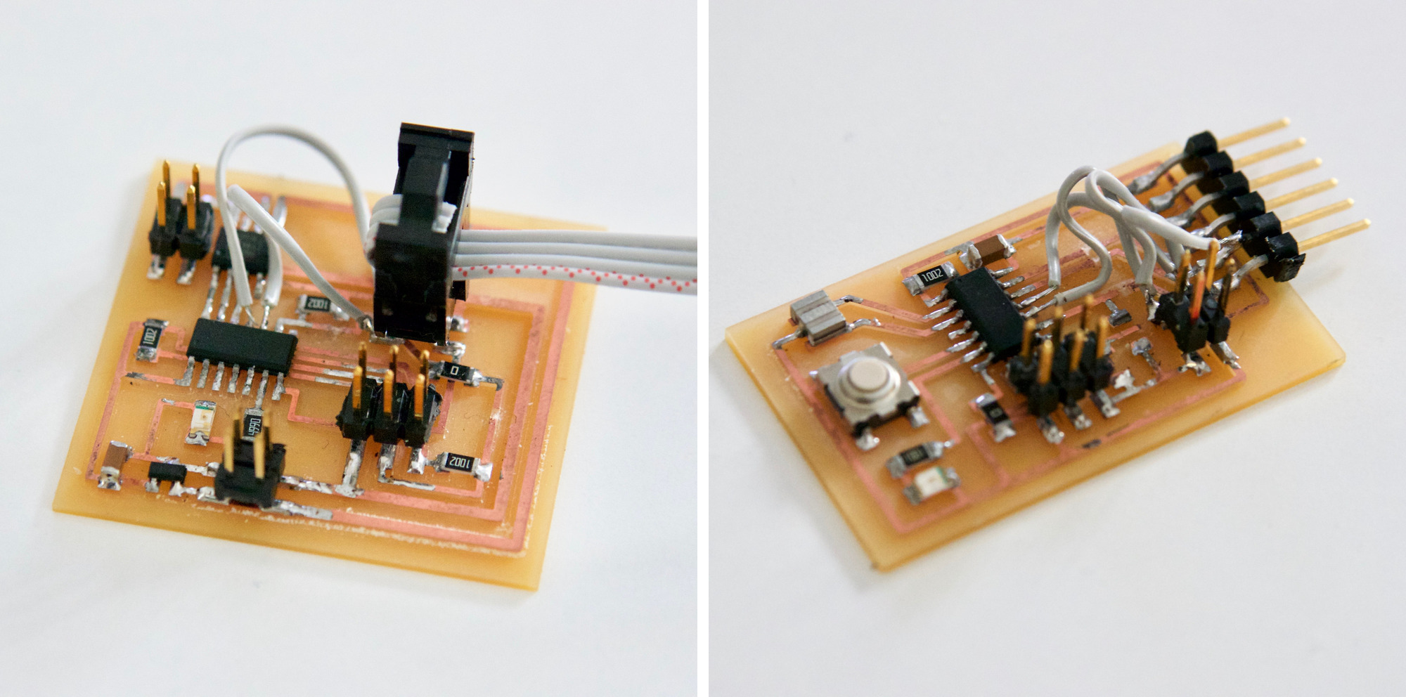
I used a small electric drill to cut the copper traces and the reconnect then with small pieces of wire. I realized that it was easier than expected to move things around, this is not a process that can be repeated many times as the board logic becomes much more difficult to read after four or five cables but it is perfect for small hacks like this one.
I tried to run the code above using the new pin configuration but to my disappointment I couldnt make it work neither. After all these trials, I finally decided to replicate the hello.bus.45 functionality that it was provided in the class, once I have this working I will try to fix my own code.
The example worked at the first time, I just need to change the led PIN to the one I was using in both boards and make sure that each board was flashed with a different ID number. The video below shows the example code in action.
This is the assignment for now, I will try to expand it further in the coming weeks.
UPDATE New networking code
At the local review it was mentioned that I was not covering addressing and identity in my code above so I gave it another go to my code.
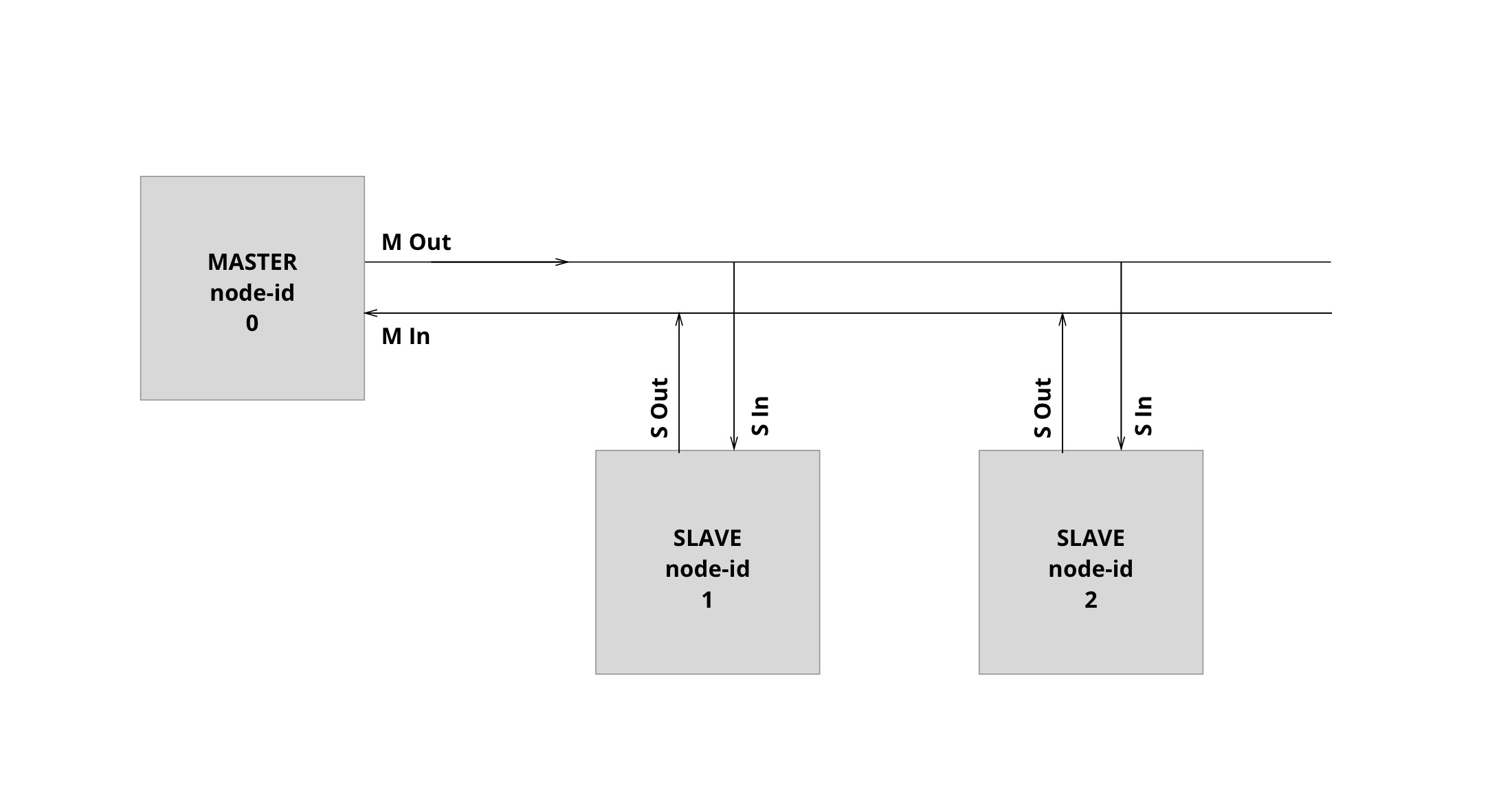
After reviewing the class again I made the avobe diagram to reflect graphically what I was trying to achieve. I will create a MASTER SLAVE network. My Master has one button and one led and all the slaves have just one button. Each board will have a node_id assigned, MASTER is node_id 0 and slaves are node_id 1, 2 and so on.
The behaviour is the following: a click is made the MASTER will talk to node number 1 via its serial port_out,SLAVES are listening all the time on their serial port_in, when they listen the message addressed to their specific node_id they change their serial port_out to output, blink their led for half a second and send their own node_id and turn back their port_out to tristate.
#include <avr/io.h>
#include <util/delay.h>
#include <avr/pgmspace.h>
#include <string.h>

// MASTER ID 0
// SLAVE ID 1
#define node_id 0

#define output(directions,pin) (directions |= pin) // set port direction for output
#define input(directions,pin) (directions &= (~pin)) // set port direction for input
#define set(port,pin) (port |= pin) // set port pin
#define clear(port,pin) (port &= (~pin)) // clear port pin
#define pin_test(pins,pin) (pins & pin) // test for port pin
#define bit_test(byte,bit) (byte & (1 << bit)) // test for bit set
#define bit_delay_time 100 // bit delay for 9600 with overhead
#define bit_delay() _delay_us(bit_delay_time) // RS232 bit delay
#define half_bit_delay() _delay_us(bit_delay_time/2) // RS232 half bit delay
#define led_delay() _delay_ms(100) // LED flash delay

// MASTER board has a button and a led and ID 0
// SLAVE board has a led and ID 1
// When button in MASTER is press once it communicates with SLAVE board
// Slave board is listening and then it changes from listening to sending and sends back a message
// This message makes the led on the MASTER board to flash

// button port in MASTER PB2
#define master_input_port PORTB
#define master_input_direction DDRB
#define master_input_pin (1 << PB2)
#define master_input_pins PINB

// led port in MASTER PA7
#define master_led_port PORTA
#define master_led_direction DDRA
#define master_led_pout (1 << PA7)

// serials port in MASTER
#define master_serial_port PORTA
#define master_serial_direction DDRA
#define master_serial_pins PINA
#define master_serial_pin_in (1 << PA3) // connector 1 goes to pin PA2. 2 is GND
#define master_serial_pin_out (1 << PA2) // connector 3 goes to pin PA3  4 is VCC

// led port in SLAVE PA7
#define slave_led_port PORTA
#define slave_led_direction DDRA
#define slave_led_pout (1 << PA7)

// serials port in SLAVE
#define slave_serial_port PORTA
#define slave_serial_direction DDRA
#define slave_serial_pins PINA
#define slave_serial_pin_in (1 << PA3) // connector 1 grey goes to pin PA2. 2 is GND
#define slave_serial_pin_out (1 << PA2) // connector 3 white goes to pin PA3. 4 is VCC


void get_char(volatile unsigned char *pins, unsigned char pin, char *rxbyte) {
   //
   // read character into rxbyte on pins pin
   //    assumes line driver (inverts bits)
   //
   *rxbyte = 0;
   while (pin_test(*pins,pin))
      //
      // wait for start bit
      //
      ;
   //
   // delay to middle of first data bit
   //
   half_bit_delay();
   bit_delay();
   //
   // unrolled loop to read data bits
   //
   if pin_test(*pins,pin)
      *rxbyte |= (1 << 0);
   else
      *rxbyte |= (0 << 0);
   bit_delay();
   if pin_test(*pins,pin)
      *rxbyte |= (1 << 1);
   else
      *rxbyte |= (0 << 1);
   bit_delay();
   if pin_test(*pins,pin)
      *rxbyte |= (1 << 2);
   else
      *rxbyte |= (0 << 2);
   bit_delay();
   if pin_test(*pins,pin)
      *rxbyte |= (1 << 3);
   else
      *rxbyte |= (0 << 3);
   bit_delay();
   if pin_test(*pins,pin)
      *rxbyte |= (1 << 4);
   else
      *rxbyte |= (0 << 4);
   bit_delay();
   if pin_test(*pins,pin)
      *rxbyte |= (1 << 5);
   else
      *rxbyte |= (0 << 5);
   bit_delay();
   if pin_test(*pins,pin)
      *rxbyte |= (1 << 6);
   else
      *rxbyte |= (0 << 6);
   bit_delay();
   if pin_test(*pins,pin)
      *rxbyte |= (1 << 7);
   else
      *rxbyte |= (0 << 7);
   //
   // wait for stop bit
   //
   bit_delay();
   half_bit_delay();
}

void put_char(volatile unsigned char *port, unsigned char pin, char txchar) {
   //
   // send character in txchar on port pin
   //    assumes line driver (inverts bits)
   //
   // start bit
   //
   clear(*port,pin);
   bit_delay();
   //
   // unrolled loop to write data bits
   //
   if bit_test(txchar,0)
      set(*port,pin);
   else
      clear(*port,pin);
   bit_delay();
   if bit_test(txchar,1)
      set(*port,pin);
   else
      clear(*port,pin);
   bit_delay();
   if bit_test(txchar,2)
      set(*port,pin);
   else
      clear(*port,pin);
   bit_delay();
   if bit_test(txchar,3)
      set(*port,pin);
   else
      clear(*port,pin);
   bit_delay();
   if bit_test(txchar,4)
      set(*port,pin);
   else
      clear(*port,pin);
   bit_delay();
   if bit_test(txchar,5)
      set(*port,pin);
   else
      clear(*port,pin);
   bit_delay();
   if bit_test(txchar,6)
      set(*port,pin);
   else
      clear(*port,pin);
   bit_delay();
   if bit_test(txchar,7)
      set(*port,pin);
   else
      clear(*port,pin);
   bit_delay();
   //
   // stop bit
   //
   set(*port,pin);
   bit_delay();
   //
   // char delay
   //
   bit_delay();
}


int main(void) {
   //
   // main
   //
   int i = 0;
   static char chr;
   // set clock divider to /1
   //
   CLKPR = (1 << CLKPCE);
   CLKPR = (0 << CLKPS3) | (0 << CLKPS2) | (0 << CLKPS1) | (0 << CLKPS0);
   //
   // initialize pins for MASTER
   if (node_id == 0) {
     // serial output pin
     clear(master_serial_port, master_serial_pin_out);
     output(master_serial_direction, master_serial_pin_out);
     // serial input pin
     clear(master_serial_port, master_serial_pin_in);
     input(master_serial_direction, master_serial_pin_in);
     // led
     clear(master_led_port, master_led_pout);
     output(master_led_direction, master_led_pout);
     // button
     set(master_input_port, master_input_pin); // turn on pull-up
     input(master_input_direction, master_input_pin);
   }
   // initialize pins for SLAVE
   if (node_id != 0) {
     // serial
     clear(slave_serial_port, slave_serial_pin_out);
     input(slave_serial_direction, slave_serial_pin_out);
     // led
     clear(slave_led_port, slave_led_pout);
     output(slave_led_direction, slave_led_pout);
   }
   //
   // main loop
   //
   while (1) {
     // This is the loop for only the MASTER
     if (node_id == 0) {
       // wait for botton down
       while (0 != pin_test(master_input_pins,master_input_pin));
       set(master_led_port, master_led_pout);
       // wait for botton up
       while (0 == pin_test(master_input_pins,master_input_pin));
       clear(master_led_port, master_led_pout);
       put_char(&master_serial_port, master_serial_pin_out, 1);
       _delay_ms(500);
     }
    // This is the loop for all the SLAVES, they are listening on the slave_serial_pin_in
    if (node_id != 0) {
      get_char(&slave_serial_pins, slave_serial_pin_in, &chr); // all SLAVES listening on the slave_serial_pin_in
      if (chr == node_id) {
         output(slave_serial_direction, slave_serial_pin_out); // Sets slave_serial_pin_out as output
         _delay_ms(500);
         put_char(&slave_serial_port, slave_serial_pin_out, chr); // Sends to master_serial_pin_in the id of the slave
         set(slave_led_port, slave_led_pout);
         _delay_ms(500);
         clear(slave_led_port, slave_led_pout);
         input(slave_serial_direction, slave_serial_pin_out); // Sets slave_serial_pin_out as tristate
      }
    }
  } // end while
} // end main