Fabacademy 2017
Eighth Week. Embedded programming
Index
Eighth task
Program your board to do something
This week we have a double task, first familiarize with the Atmel ATtiny44 datasheet and second program our modified Hello board to do something. I was away last week so my CNC tasks –baby walker and window– were done last weekend, only three days for this week task I'm afraid!
In week six I managed to program the Hello Board with the hello.ftdi.44.echo.c example using my FabTinyISP programmer, everything worked as expected so I will be using that code as the basis of my new program. Also I got a number of Arduino .ino examples so I would like to set up Arduino IDE to program my Hello Board as well.
The setup
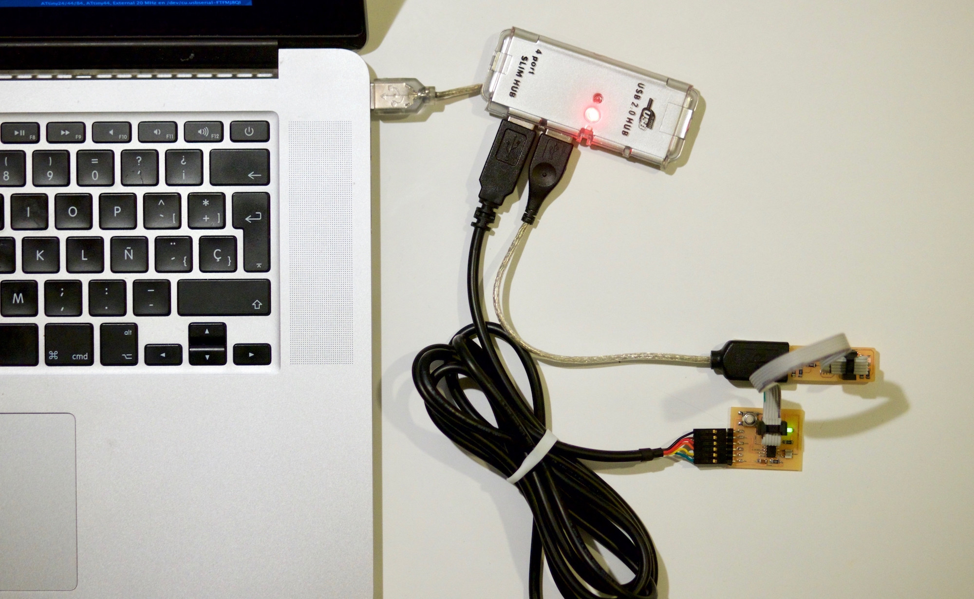
Regarding the physical setup, no changes from week 6: FTDI cable connects computer to board, ISP ribbon cable connects board to FabTinyISP programmer and usb pins of FabTinyISP connected to computer.
Software setup, for C programs we need GCC, the GNU Compiler Collection, if you are using Mac as I am you just need to install Xcode or just the Xcode command line tools Tutorial here. Final element would be to install avrdude and the avr-gcc toolchain, simplest way is to do it via Homebrew, a complete tutorial here.
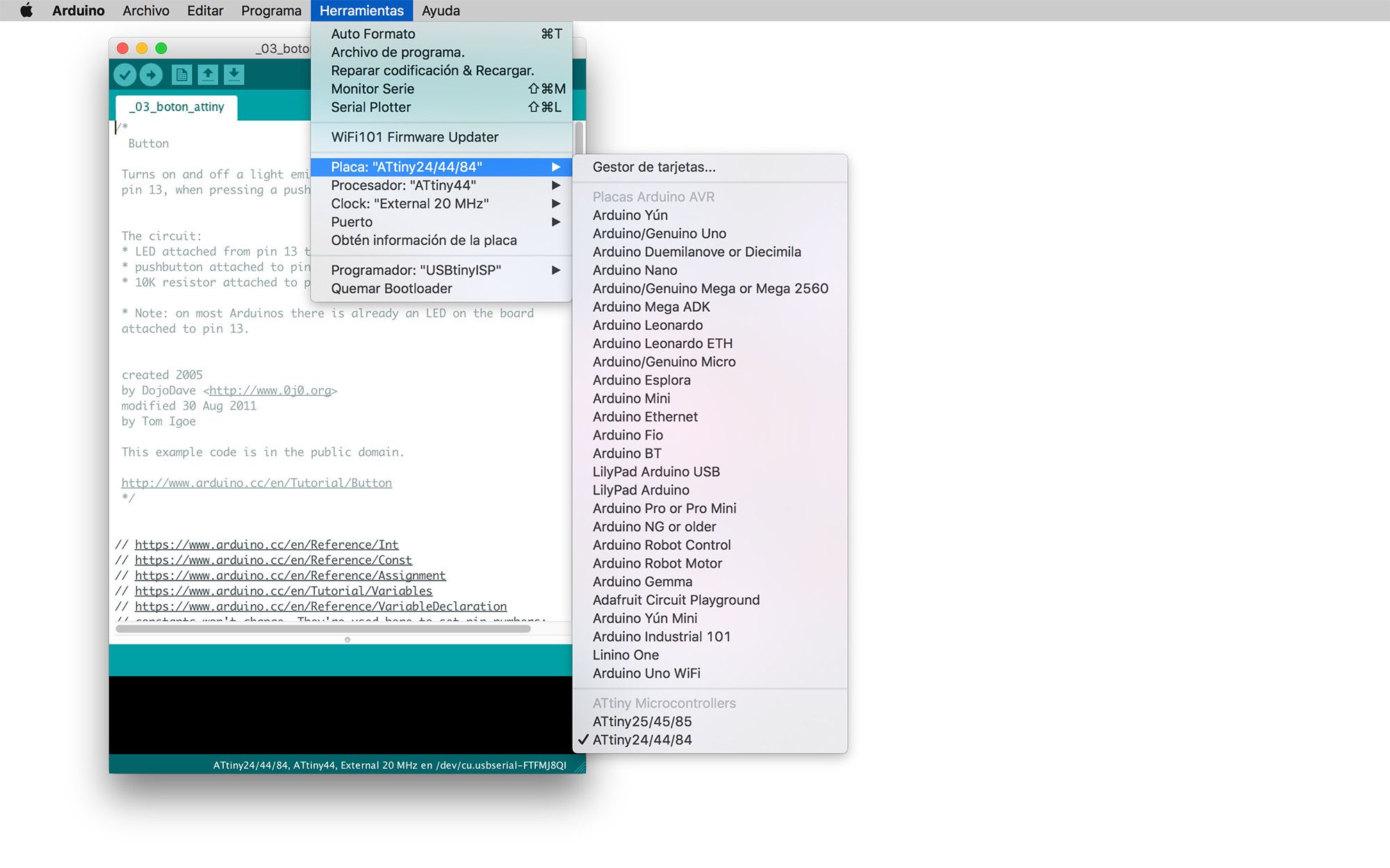
In order to use Arduino Integrated Development Environment you need to follow this complete tutorial. The board manager in Arduino>Tools>Board Manager makes the process quite straight forward, just make sure that you have add https://raw.githubusercontent.com/damellis/attiny/ide-1.6.x-boards-manager/package_damellis_attiny_index.json this url in the "Additional Boards Manager" field in the Arduino General Preferences dialog.
Once attiny is added as custom board, you will be able to select the board "ATtiny24/44/84", processor –pick one of these three– and clock speed –in our case we can make use of the external 20mHz crystal that– on menu>tools. If you are using your FabTinyISP don't forget to select USBtinyISP as the programmer.
Reading the datasheet
The Atmel ATtiny44 microcontroller is a low power –chapter 20. Electrical characteristics– 8-bit microcontroller with 4k Bytes of In-System Programmable Program Memory FLASH and 256 Bytes of In-System Programmable EEPROM and 256 Bytes of Internal SRAM –chapter 5. Memories–
| SRAM | memory for storing your data which are processed during the run time (including also the registers) volatile memory |
|---|---|
| FLASH | memory which your program stored - non volatile. Endurance: 10,000 Write/Erase Cycles |
| EEPROM | memory which can be used for storing non volatile data and changeable during run-time. (for example: setting values) Endurance: 100,000 Write/Erase Cycles |
The ATtiny has the following main modules:
- One 8-Bit Timer/Counter with Two Pulse Width Modulation Channels. The timer/counter allows accurate program execution timing, event management, and wave generation. It has Pulse Width Modulation support. Chapter 11
- One 16-Bit Timer/Counter with Two Pulse Width Modulation Channels. Chapter 12
- One 10-bit Analog to Digital Converter. It converts an analog input voltage to a 10-bit digital value. The minimum value represents GND and the maximum value represents the reference voltage. The voltage reference can be selected between the VCC supply, a specific pin or an internal 1.1V voltage reference. Chapter 16
- One Analog Comparator. It compares two analog input voltages and outputs a signal level indicating which of the inputs is greater or lesser. Chapter 15
- Universal Serial Interface for I2C communications. It provides the basic hardware resources needed for serial communication allowing significantly higher transfer rates and less code than software solutions. Chapter 14
The ATtiny has twelve Programmable I/O Lines. All of them have true Read-Modify-Write functionality, and can be set individually to imput output or tristate as well as enabling and disabling pull-up resistors when set as input. Chapter 10
ATtiny datasheet is referenced in the following week tasks:
- Week10 - ATtiny GPIO Ports
- Week13 - ATtiny Analog Digital converter
- Week15 - Universal Serial Interface
For this week task I will be focussing just on controlling the programmable I/O pins. In the chapter below it is described the parts of the datasheet that were used.
What questions do you have? What would you like to learn more about?
It is my first time reading this type of documentation and right now there is too much information and everything is really sketchy in my head. I understand that in order to switch on and off pins, read pin information and control all the features of the microcontroller I have to write and read 8-bit instructions in the data registers –ie. DDRA 0b10000000 sets pin PA7 to be output– Many features and functions need several data registers to operate. Also, timing feels really important and there are several counters –internal and externals– and clocks to timing all this data reading and writing with precision.
Too many questions at the moment. I imagine that all this data registry reading and writing is done sequentially, right? So timing becomes extremely important. Can I interpolate different steps or this can cause problems? I think these microcontrollers don't do multiple tasks at the same time, right?
Arduino and C AVR libraries provide some helpful features and variables to do all this. I am more inclined to try to learn this at the lowest level as I can so I will be able to set a good foundation for future self-learning.
Two Arduino examples: led and button
I uploaded two arduino examples, first a led blinking and second a led turned on and off when pressing the button. The only changes that I have to do is making sure that the pins used were the correct ones. PA7 se as an output for the led and PA3 set as an input for the push button.
/*
  Blink
  Turns on an LED on for one second, then off for one second, repeatedly.
*/
// the setup function runs once when you press reset or power the board
void setup() {
  // initialize digital pin LED_BUILTIN as an output.
  pinMode(7, OUTPUT);
}

// the loop function runs over and over again forever
void loop() {
  digitalWrite(7, HIGH);   // turn the LED on (HIGH is the voltage level)
  delay(500);                       // wait for a second
  digitalWrite(7, LOW);    // turn the LED off by making the voltage LOW
  delay(500);                       // wait for a second
}
/*
  Button

 Turns on and off a light emitting diode(LED) when pressing a pushbutton attached.

 http://www.arduino.cc/en/Tutorial/Button
 */

// constants won't change. They're used here to set pin numbers:
const int buttonPin = 3;     // the number of the pushbutton pin
const int ledPin =  7;      // the number of the LED pin

// variables will change:
int buttonState = 0;         // variable for reading the pushbutton status


void setup() {
  // initialize the LED pin as an output:
  pinMode(ledPin, OUTPUT);
  // initialize the pushbutton pin as an input_pullup:
  pinMode(buttonPin, INPUT_PULLUP);
}

void loop() {
  // read the state of the pushbutton value:
  buttonState = digitalRead(buttonPin);

  // check if the pushbutton is pressed. if it is, the buttonState is LOW:
  if (buttonState == LOW) {
    // turn LED on:
    digitalWrite(ledPin, HIGH);
  } else {
    // turn LED off:
    digitalWrite(ledPin, LOW);
  }
}
Giving a try on C
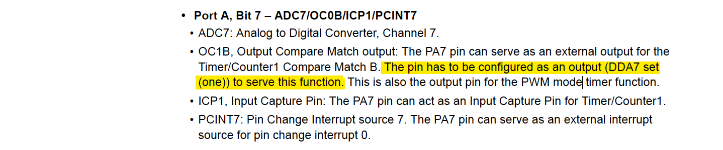
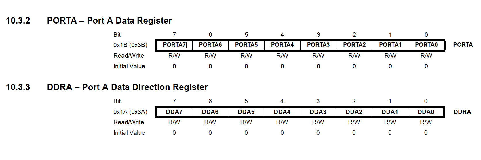
I had to find how to asign pin7 PA7 as an output and how to set it to high and low to turn the led on and off. In page 3 it describes the Port A as a 8-bit bidirectional I/O port. In page 66, 10.3.2 and 10.3.3 it describes how to set up PA7 direction and content. So I need to specify in binary the register DDRA to set PA7 to be output and alternate register PORTA to set PA7 to high and low values.


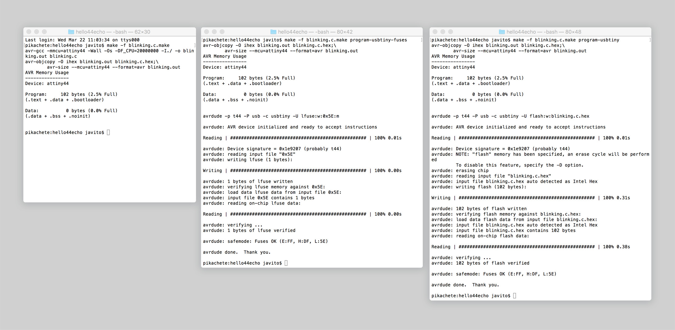
I used hello.ftidi.44.echo.c.make for compiling the hex and flashing the ATtiny. I found this other example which does a LED blinking but in a ATtnity85, registers are different but the code is similar.
#include <avr/io.h>
#include <util/delay.h>


int main (void)
{
  // set PA7 to be output
	DDRA = 0b10000000;
  while (1) {

    // set PA7 high
    PORTA = 0b10000000;
    _delay_ms(500);
    // set PA7 low
    PORTA = 0b00000000;
    _delay_ms(500);

  }
  return 1;
}
The code worked without issues and the board's led blinked as expected. Like in the Arduino example, it doesn't feel to me that is switching on and off in a 500ms interval, might be a clock problem but I didn't have time to find out more.
Finally, I coded myself a program to switch on and off the led when the button is pressed. First, I set up PA3 as an input and PA7 as an output. As I'm using a button switch I need to set up the PA3 as pull-up resistor so when PINA3 is 1 it means that the button is not pressed and when 0 the button is pressed. Then, I read the PINA byte and create a conditional to switch on and off the led when button is pressed or not. Code and video below:
#include <avr/io.h>
#include <util/delay.h>
int buttonState = 0;
int main (void)
{
  //  PA3 as input & PA7 as output
  DDRA = 0b10000000;
  // PA3 button as pull-up resistor
	PORTA = 0b00001000;
  while (1) {
    // Read buttonState
    buttonState = PINA;
    // if PINA3 is 1 button is not pressed, if 0 button is pressed
    if(buttonState == 0b00001000) {
      // set PA7 high turn off led
      PORTA = 0b00001000;
    } else {
      // set PA7 low turn on led
      PORTA = 0b10001000;
    }
  }
  return 1;
}