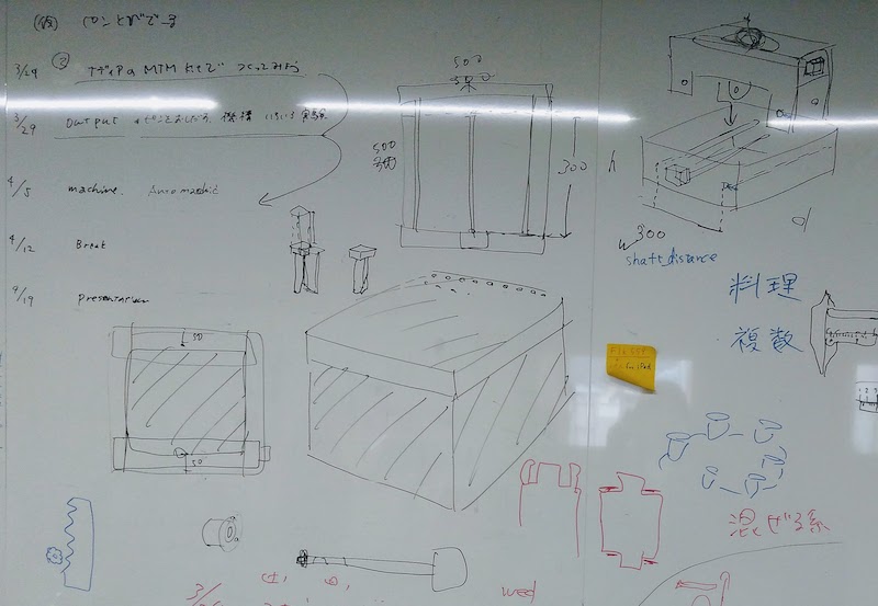
mechanical design
This week we made a manual prototype of our machine that push pins.I was in charge of gantry's modeling and pin table.
plan
We plan to make relief plotter. It coverd by pins and pins are pushed up. Like below.
I wanted to make thing that vizualize data with map in 3D.
For example, The more population in the prefecture, the higher the pin that represents that prefecture, like a 3D bar chart.
 After discussing in the group,in order to have versatility,pins are spread all over the surface to raise any place, rather than just raising the prefecture.
image
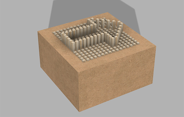
image2
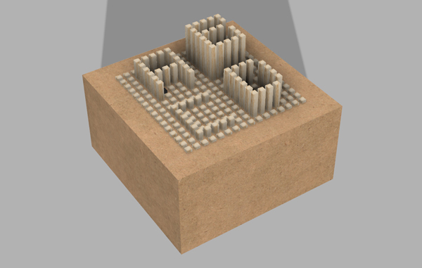
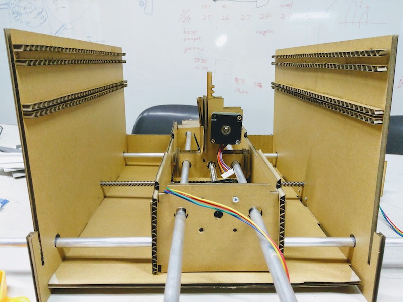
The pushed pin is held up. Control which pin is to be pushed up by the xy axis motor and how much it is pushed up is controlled with the z axis motor. For the X and Y axes, we use the motor and mechanism of MTM, the housing is made by ourselves. (The data of the original MTM was too large for our laser cutter and I wanted to make it with the metric) For the Z axis we decided to use rack and pinion.
manual prototype
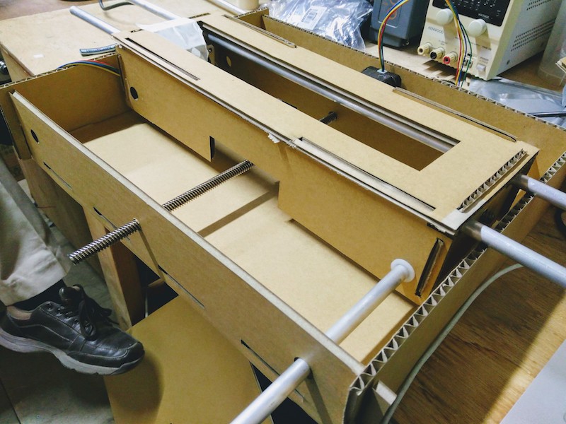
We made a prototype1 in cardboard. We are going to make final type with MDF. We are going to insert a pin in the hole at the top.
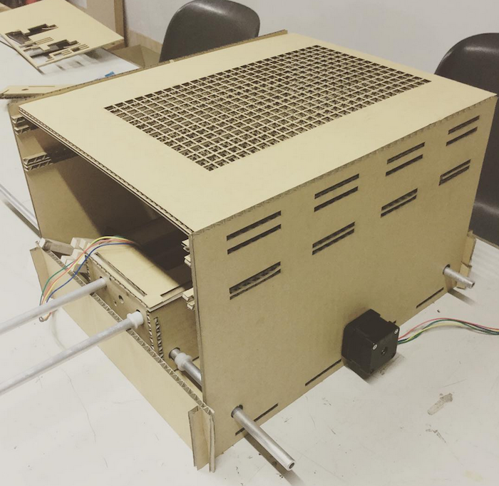
Internal structure. Push up the pin in the middle part.
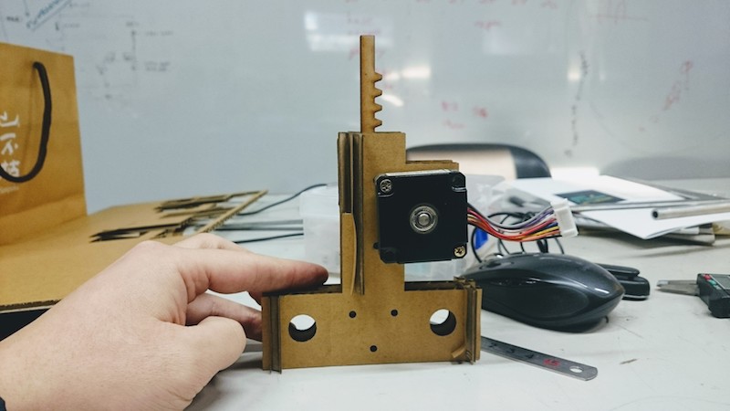
Like below.Since the width of the pin and the pushing mechanism is small, it can not be extruded too much, so it is necessary to improve.
pintable
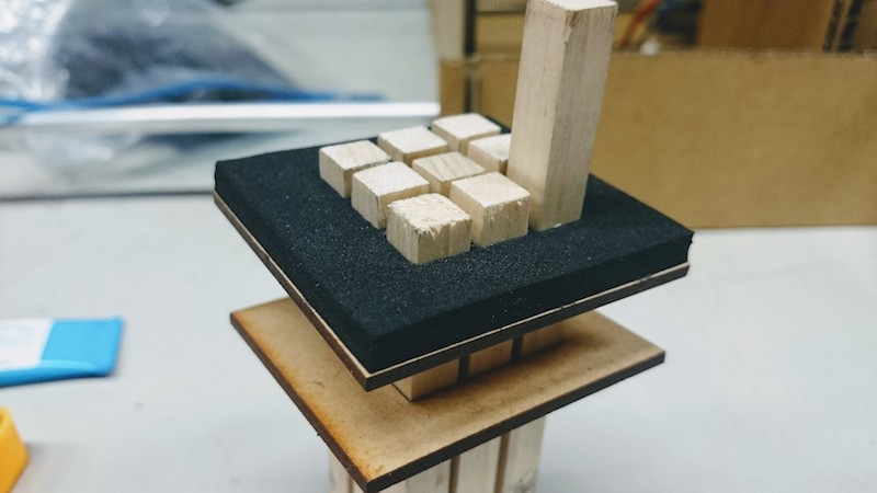
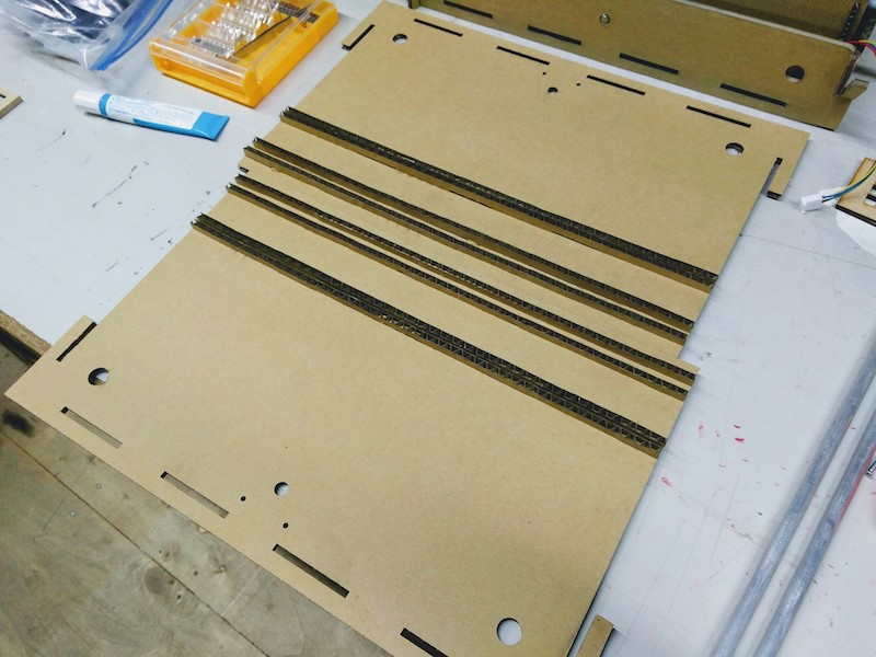
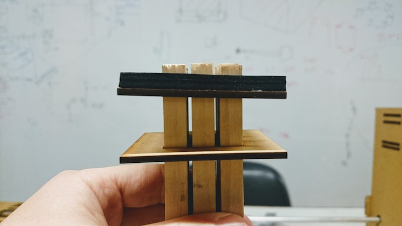
These pins are holds with a rubber sponge, and attached two MDFs to support. The hole of the rubber sponge is smaller than the thickness of the pin, and the hole of the MDF is larger than the thickness of the pin.
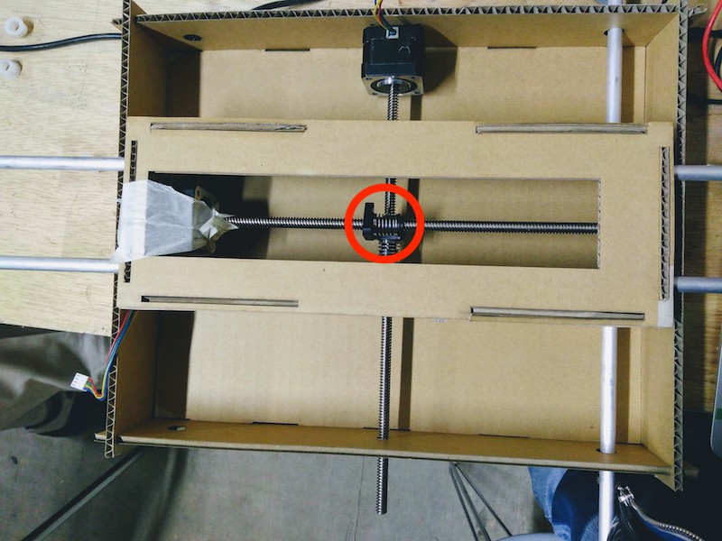
pin-push part
Pin-push part used rack and pinion.Turn the motor and the rack pops out.
my part
I made outside and pin table.
box
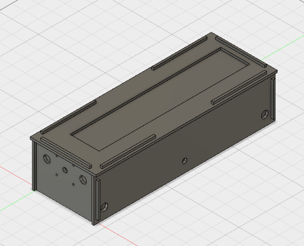
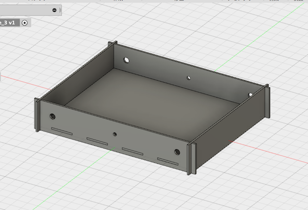
Mr.Morimoto make base part and I made upper part.
When cut and assembled, the triangle part to be moved interfered, so I increased the upper part height.
To attach pin table, I make wall with base part.
pin table
The pins should be kept not to fall off, but on the other hand they have to bea able to be rise. It must be held with optimal force that is not too strong and not too strong. The ploblem is solves by using rubber elasticity. Just because the size of hole is important, I have tested several patterns.
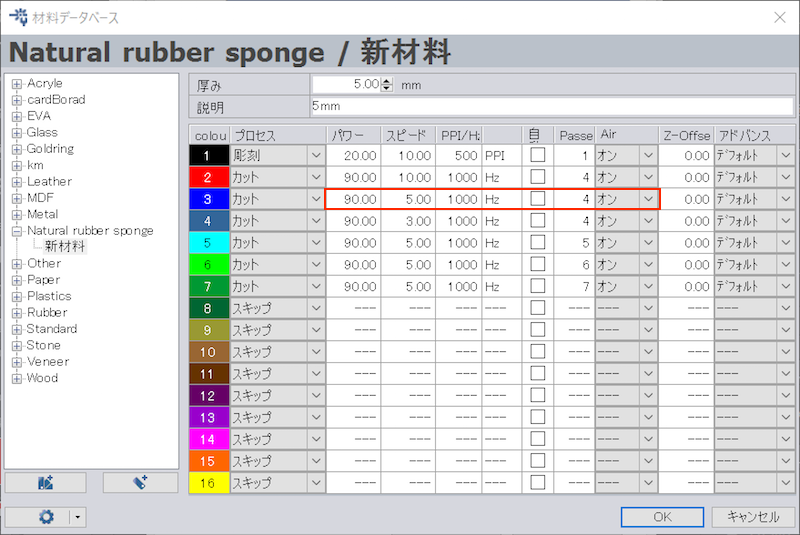
First, I tested parameters of cutting rubber.
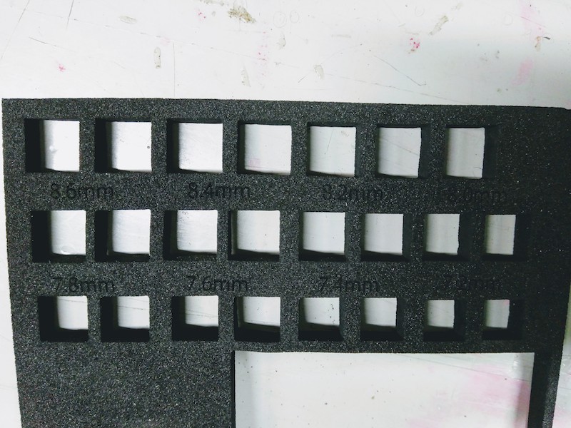
Next, we made something that changed the hole size by 0.1 mm and tested. 8.4mm Was just retained well.
If these pins goes up obliquely these will hit, so I added MDF board down to make these vertical.
These can be raised with a finger, but these do not falling.