Input Devices
For this assigment, we have to:
- (DONE) Measure something: add a sensor to a microcontroller board that you have designed and read it..
All the files created for this assigment can be found on the link bellow:
---> DOWNLOAD FILES<---
Have you:
- Described your design and fabrication process using words/images/screenshots.?
--> yes
- Explained the programming process/es you used and how the microcontroller datasheet helped you?
--> yes
- Explained problems and how you fixed them?
--> yes
- Included original design files and code?
--> yes
Measuring with microcontrollers
Most microcontrollers have digital and analog inputs. This means, that they can read digital signals like logical zeros (0 volts) or logical ones (5 volts) by their digital inputs and can read a range of voltages (from 0 to 5 volts) by their analog inputs. This analog reads can only be achieved if the microcontroller counts with an internal analog to digital converter(ADC). This analog pins usually can work as digital input or output pins. However, When one of those pins act as an analog input, the rest of the pins of the port have to act as an input too; this means that the pins on the port can not be digital outputs when at least one of the pins on the port is acting as an analog input.
Designing The Circuit
I did a board thinking that I was going to connect an ultrasonic sensor, a Hall effect sensor and any sensor that acted as an impedance (when the ultrasonic was not conected). Also, I wanted to use an attiny45 since I had not used this microcontroller before.
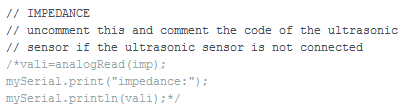
The attinny 45 has 2 digital pins and 3 analog inputs available (when not fused permanently), and I needed two digital pins for the ultrasonic sensor, one analog input for the hall effect sensor, one analog input for the impedance, and two digital pins for the serial comunication, in total 6 pins. So, since I had only five pins on the microcontroller, I had to use one of the ultrasonic sensor pins for the impedance; which means that I could not be able use the impedance and the ultrasonic sensor at the same time
I did all of this connections between the microcontroller and the sensors on an Eagle schematic, this can be seen on the image below:

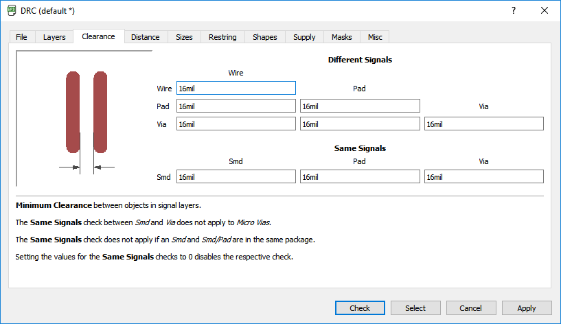
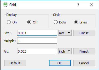
Once finished schematic, I started to made the board of the circuit. For doing this I setted all the spacing between pads and wires to 16 mil which is a little bigger than 1/64 inches and changed the grid to 0.001 mm
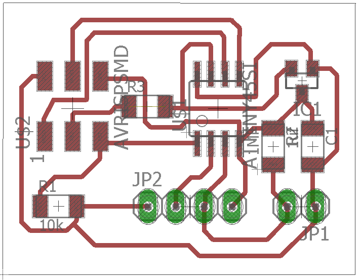
Once I finished the board, I draw a rectangle around the board for delimiting the path that was going to be cutten by the milling machine.
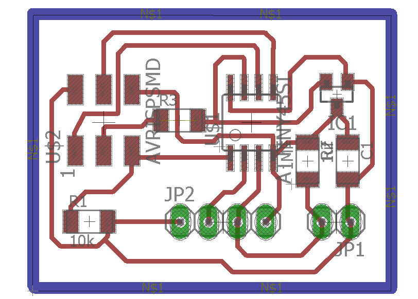
Then, on the layer settings I selected the top, botton, vias and pads as visible.
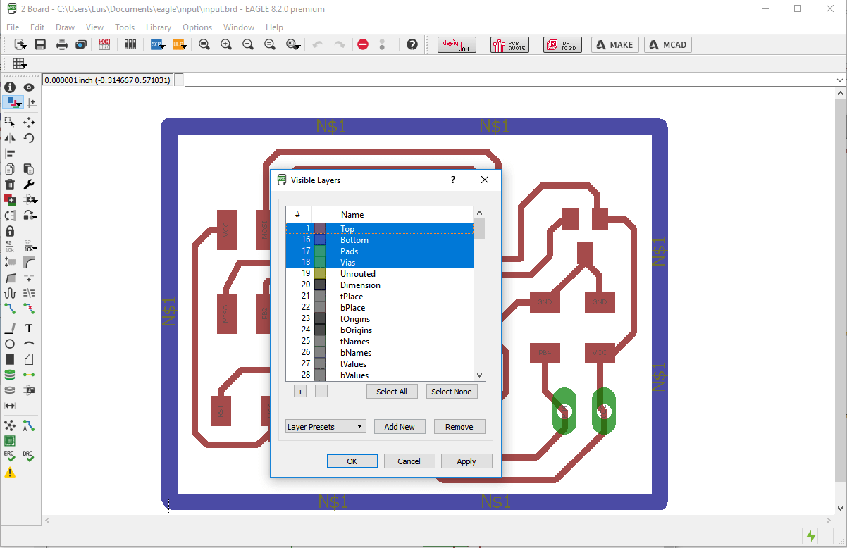
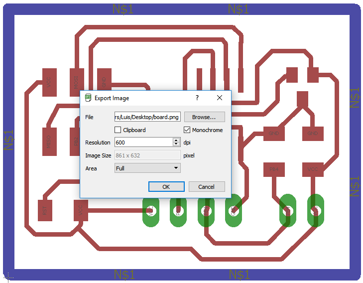
And exported the image with a 600 dpi resolution and the monochrome option active and named it as "boardlim".
Then, I oppened the image on paint and editted its dimensions.
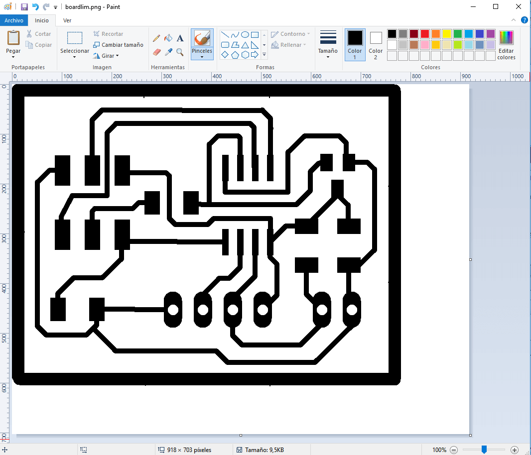
After that, I created two copies of that image, and named each one as board and limits.
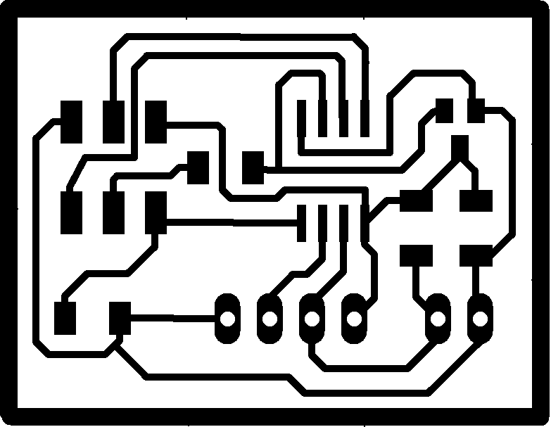
Then, I oppened the board file on paint, erased the external rectangle, inverted the color and saved it as "board" .
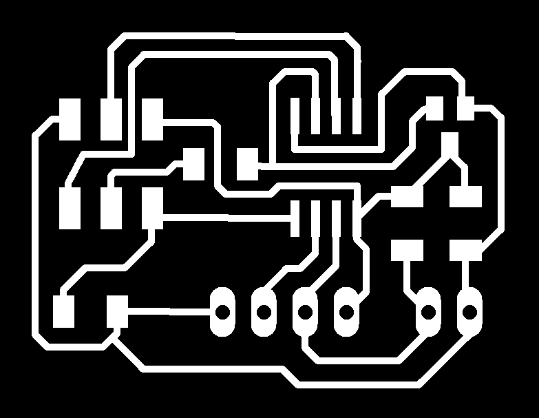
I oppened the limits file on paint, erased all except the external rectangle and saved the file as "limits".

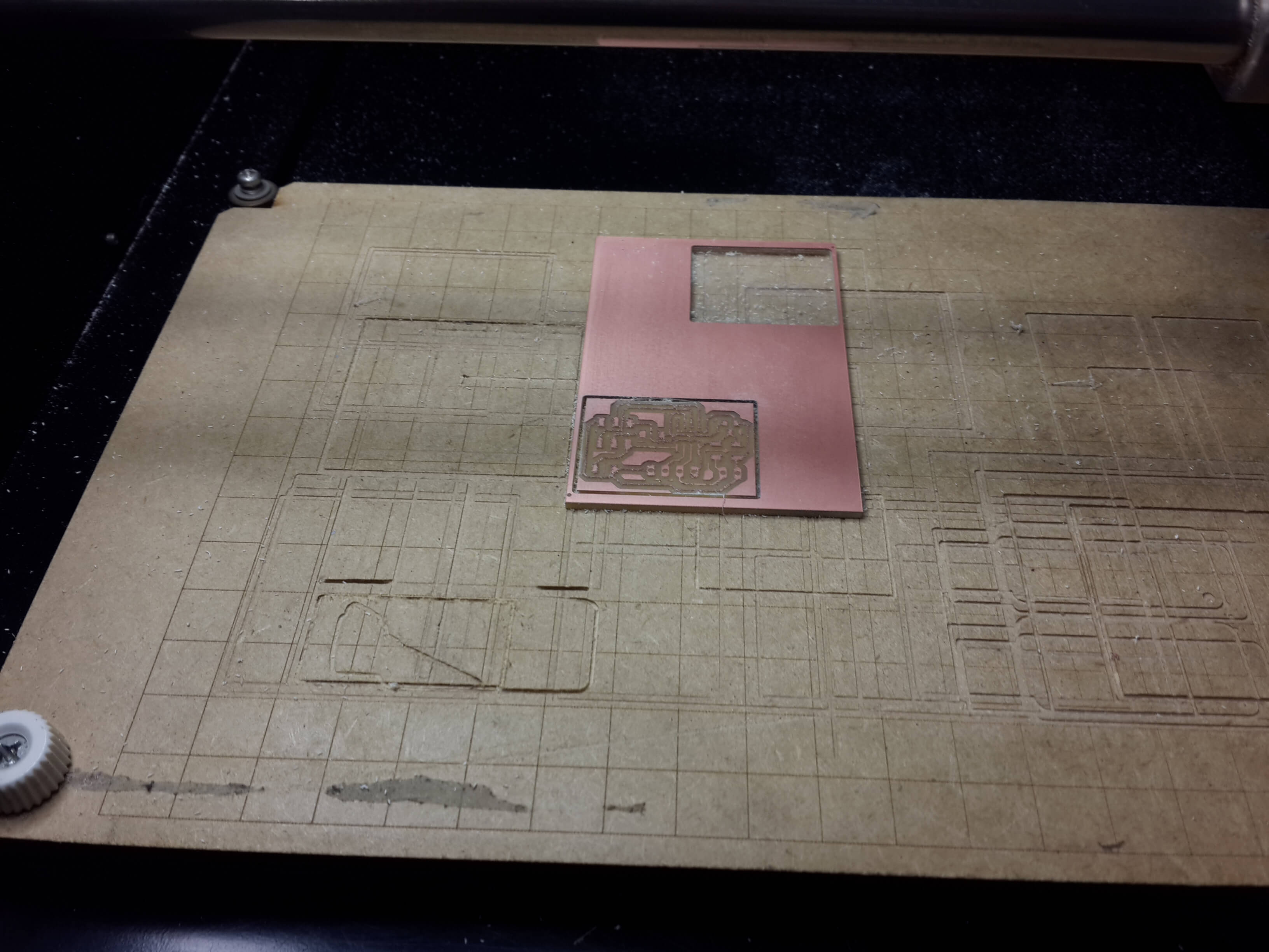
Making the Board
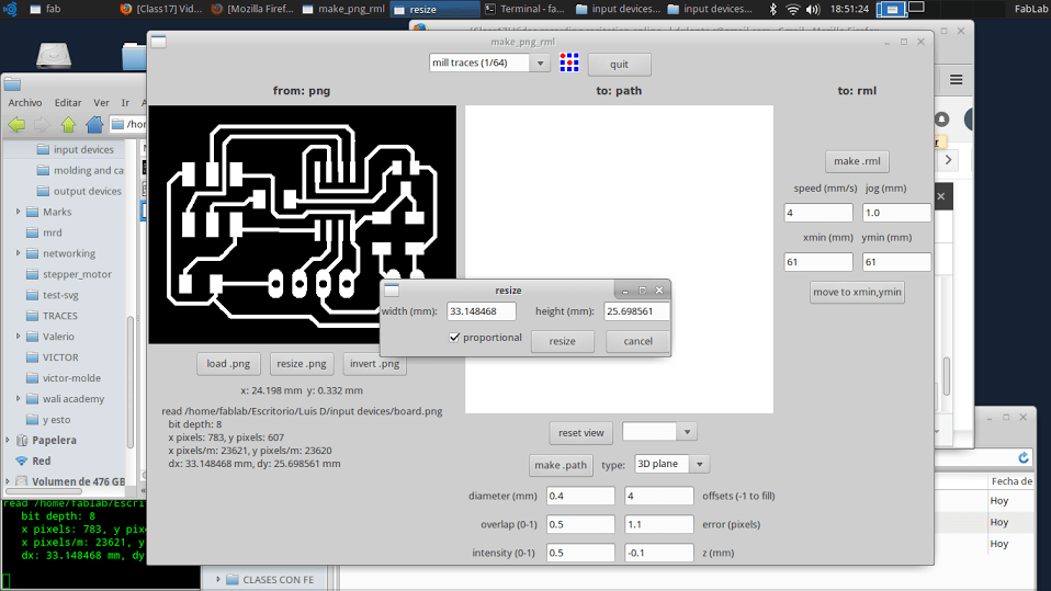
I oppened the fab modules and loaded the boardlim image, which is the image that was not editted, clicked on resize, coppied the width of the image and clicked on cancel.
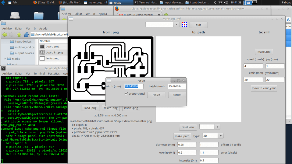
Then I loaded the board image, clicked on resize and pasted on the width field the width of the boarlim image. And then I did the same on the limits image.
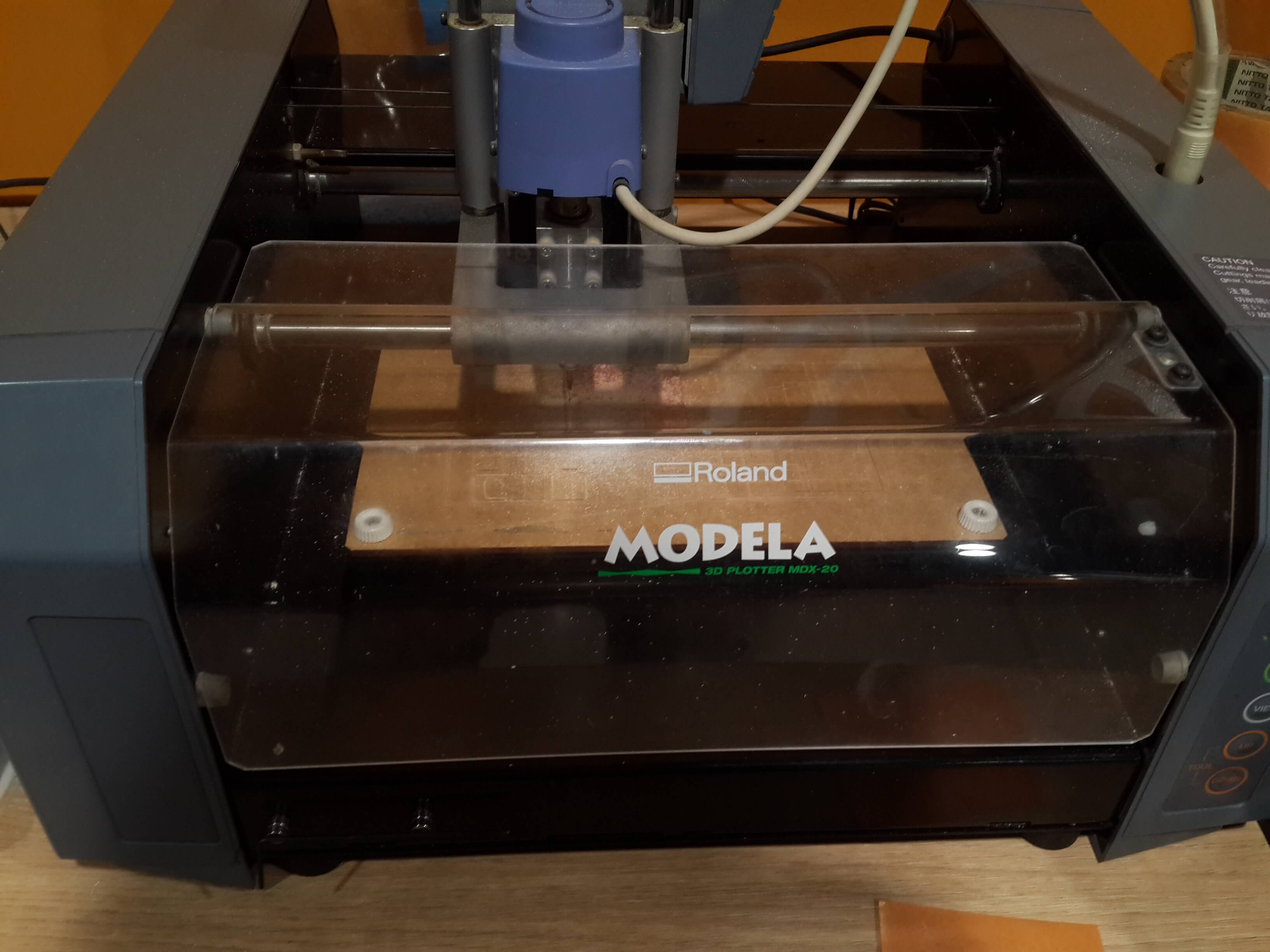
The rest of the procedure it is the same explained here for working with the milling machine MDX-20.
Programming the Microcontroller
Since I had made an output device board before, I wanted to connect the input and output device board for this assigment by serial communication, however when I tested the serial comunication on the output device board I got a lot of garbage since the heat produced by the voltage regulator on that board was generating termic noise, So I decided to replace that board with an Arduino UNO.
a) Programming the Input Device Board
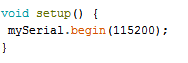
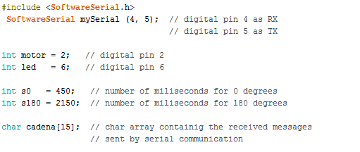
So knowing that the attiny 45 did not have an UART for serial communication and that the arduino IDE had a library called software serial, which implements serial comunication on a couple of digital pins, I decided to program the input device board using the arduino IDE, so that I could use that library. In general, this are the steps I did for programming this microcontroller:
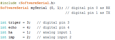
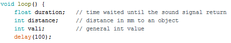
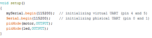
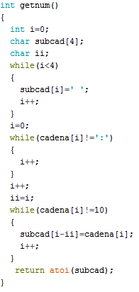
1. I started programming by including the software serial library, defining the serial comunication pins and defining the pin names.
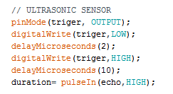
7. Then, I inmediatelly read the echo pin and got the time interval of time until the high pulse returned to the ultrasonic sensor.
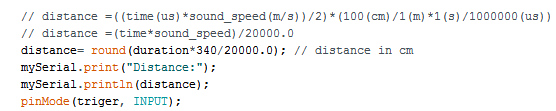
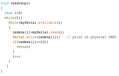
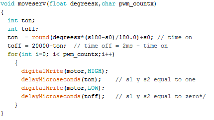
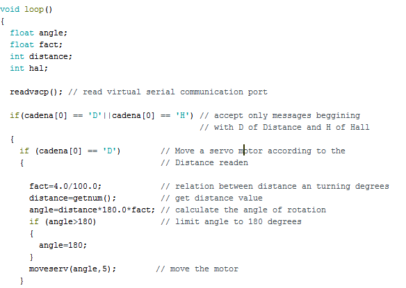
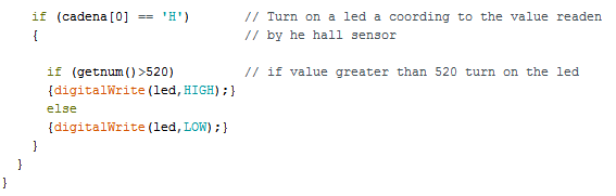
The Arduino had as tasks to read the messages sent by serial communication and take an action over a led and a servo motor connected to it.
If the char array started with D of Distance I calculated the angle of rotation of the servo motor based on the distance of an object to the ultrasonic sensor.
Uploading the programs
This are the steps I did for uploading the programs to the microcontrolers:
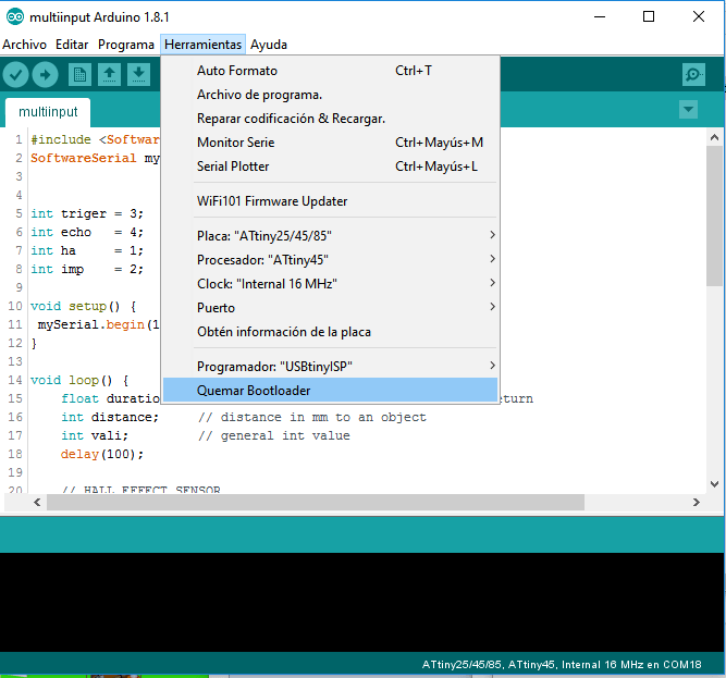
For the input device board, I selected the next configuration an the Arduino IDE:
Board: ATtiny25/45/85
Processor: ATtiny45
Clock: Internal 16 MHz
Programmer: USBtinyISP
I powered the board and connected the USB tiny ISP Programmer to it.
Then, I clicked on Burn bootloader, for setting the fuses to work with the internal clock of 16 MHz.
Then, I clicked o upload.
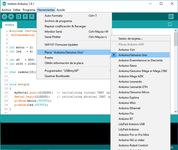
For uploading the program on the Arduino Uno, I just connected the Arduino to my pc with the USB cable, changed the board to Arduino/Genuino uno, and clicked on upload.
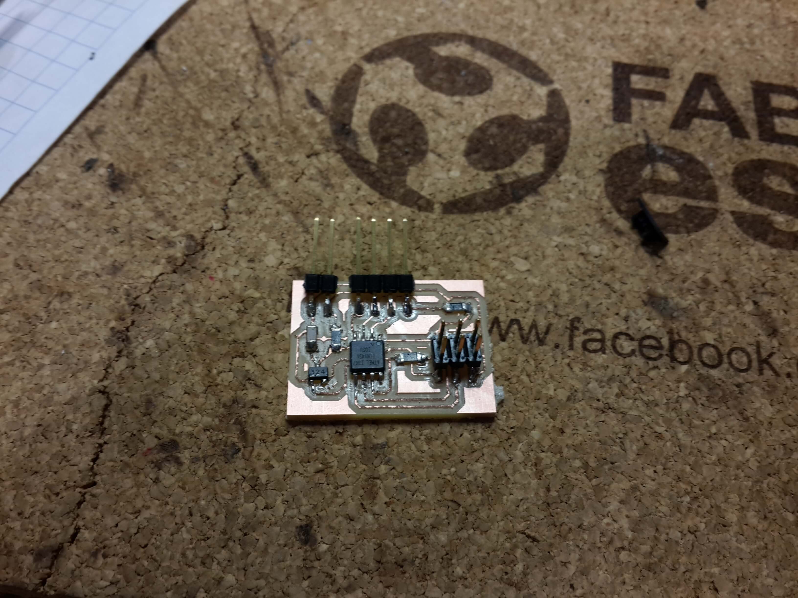
This is the final result: