Output Devices
For this assigment, we have to:
- (DONE) Add an output device to a microcontroller board you've designed and program it to do something.
All the files created for this assigment can be found on the link bellow:
---> DOWNLOAD FILES<---
Have you:
- Described your design and fabrication process using words/images/screenshots.?
--> yes
- Explained the programming process/es you used and how the microcontroller datasheet helped you?
--> yes
- Outlined problems and how you fixed them?
--> yes
- Included original design files and code?
--> yes
Designing The Circuit
The Servo motor does not need any extra component but neeeds a power sorce of 5 volts. On the other hand, the stepper motor needs a 12 volt power source and a couple of H-Bridges, this transforms the voltage of digital signals of control (5 volt) to a reference power voltage (12 volts in this case). So for having a unique power source, I put a 12 volt power source as the unique input of my circuit, added a 5 volt voltage regulator, which powered all the chipsets inside the circuit and put as a power voltage reference of the H-Bridges the 12 vol input of the circuit.
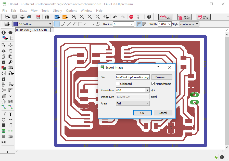
This can be seen on the eagle schematic:
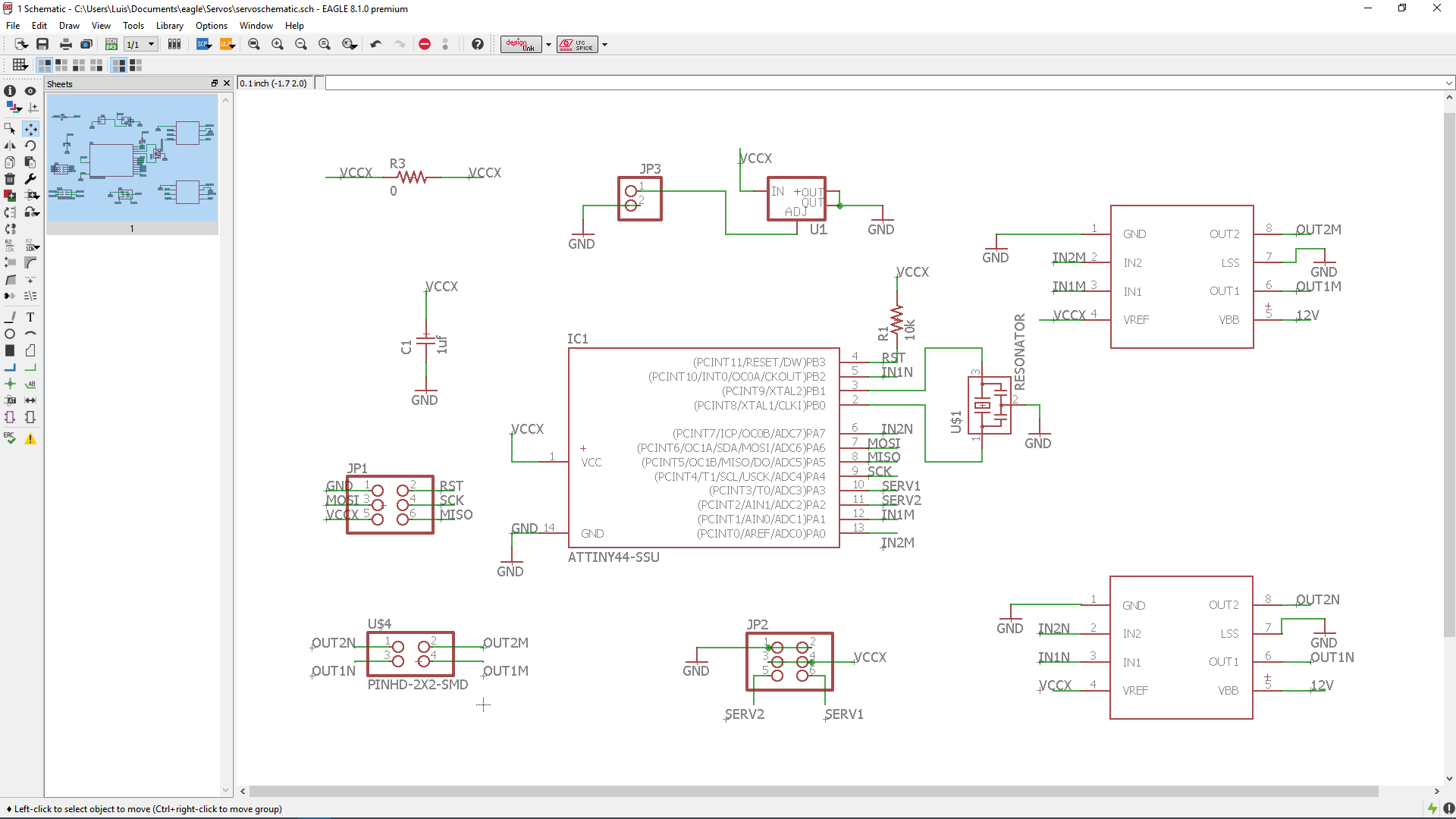
Just to mention, the sot223 voltage regulator chipset included in the fab library has a different configuration of pins of a usual voltage regulator. So I had to read the data sheet of the voltage regulator I used and wired the conections according to the datasheet.
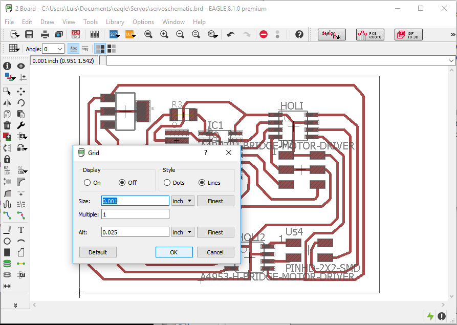
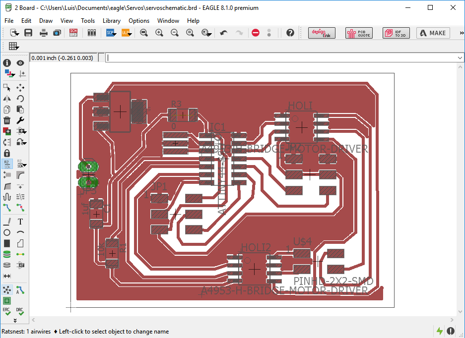
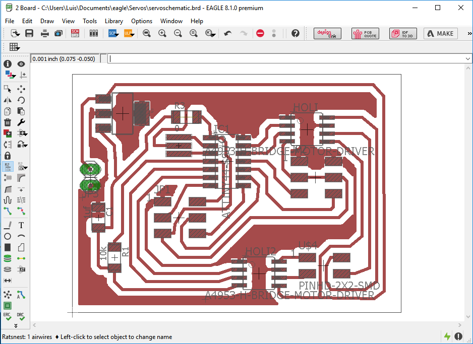
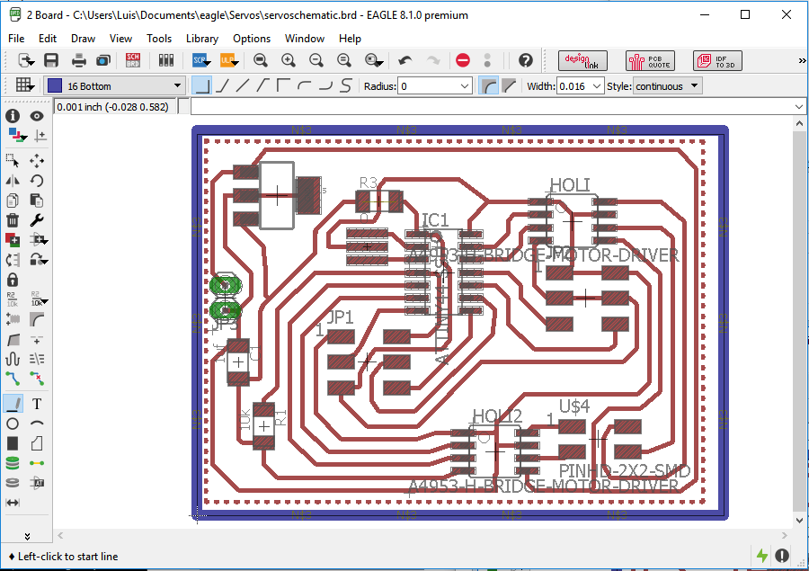
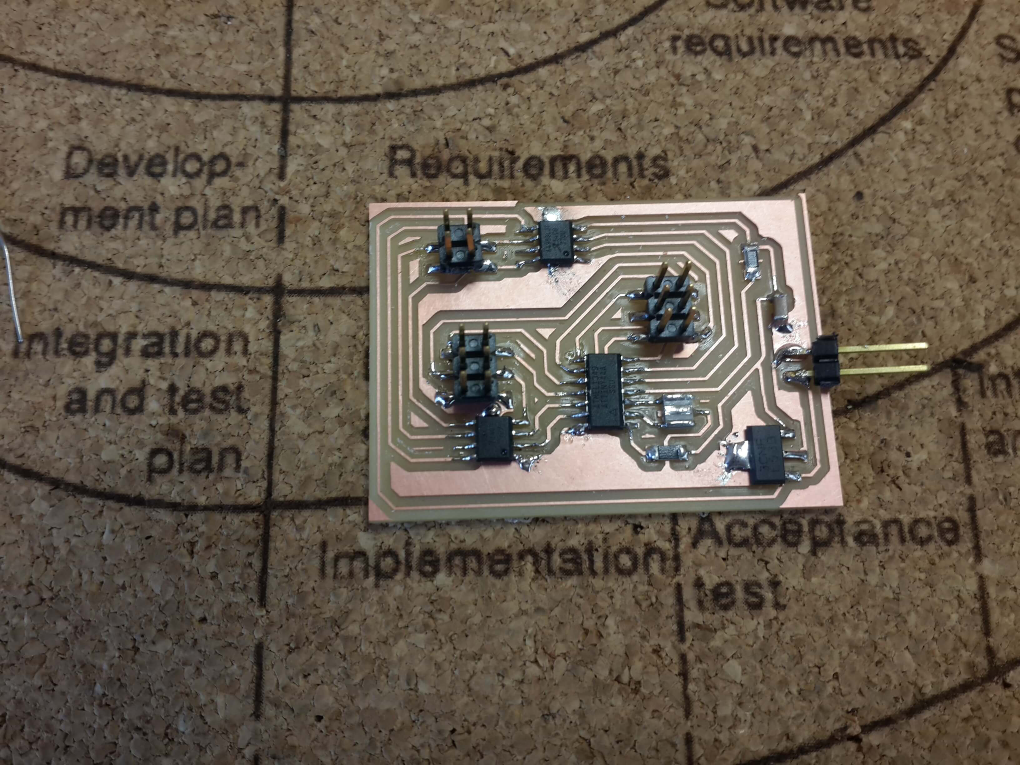
Once I had the schematic, I made the board of the circuit.
In this case, I had some problems finding routes in the circuit since the grid forced me to put the the paths close to the pins, so I did all athe connections without having care if some paths overlapped some pins, and then changed the grid size to 0.001 inches and moved the paths right on the middle of adjacent pins
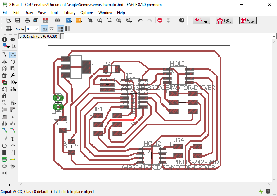
Since I knew that this kind of circuit released heat and that the dissipators of heat of the chipset were connected to GND, I left empty big parts of the board next to GND signals, so that this parts were then filled with GND, having as a result big parts of the circuit disipating all the heat.
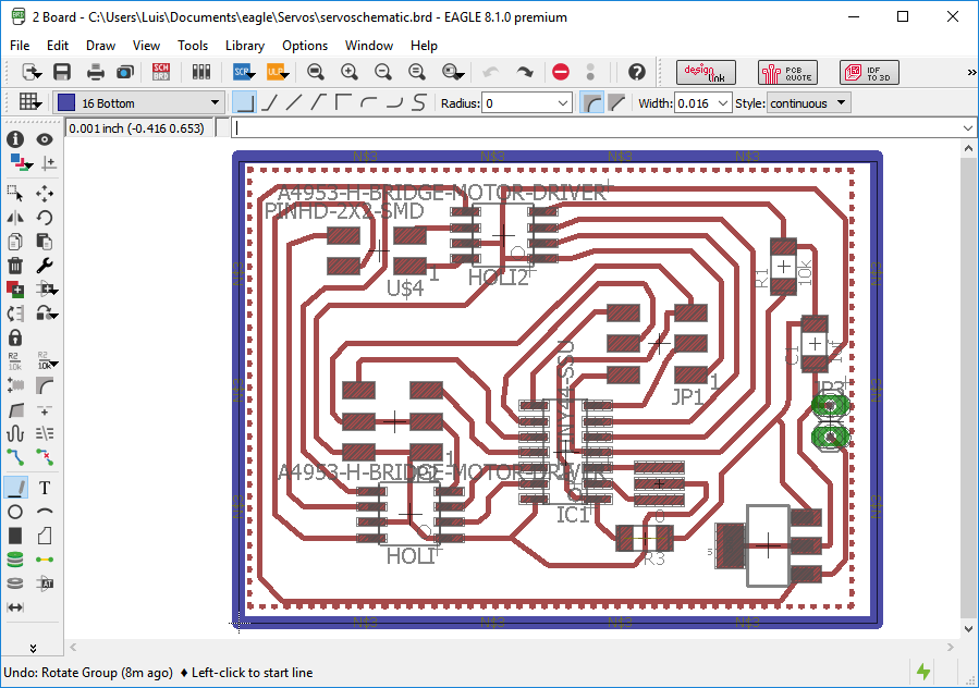
For doing this, I did the next steps:
1. I draw a poligon around the circuit
2. Named the polygon as GND, to conect the polygon to the GND signal
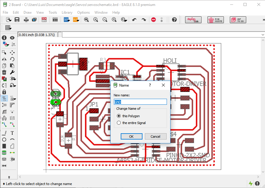
3. And then clicked on ratsnets
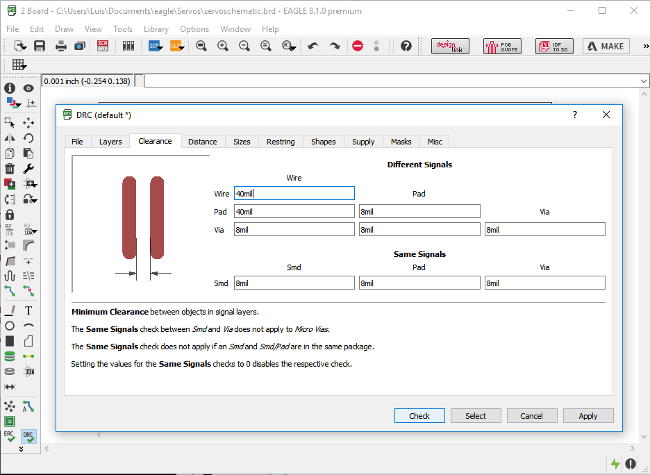
4. Since the signals were to close, and would have being a problem when the circuit was milled, I modified the minimum distance to paths and pads as 40 mill, which is a little bit bigger than the size of the 1/64'' miller used for milling the circuit, by clicking on DRC.
5. And finally, clicked again on Ratsnet
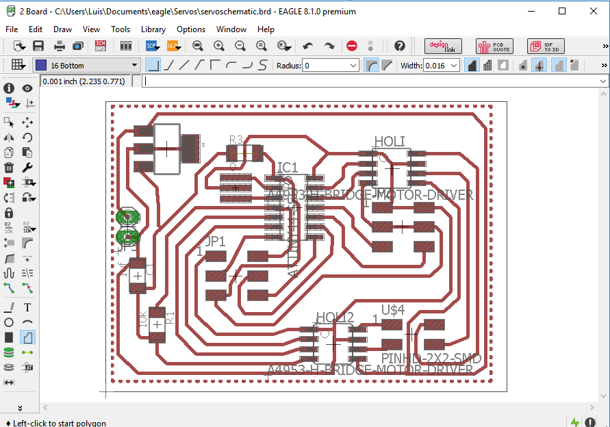
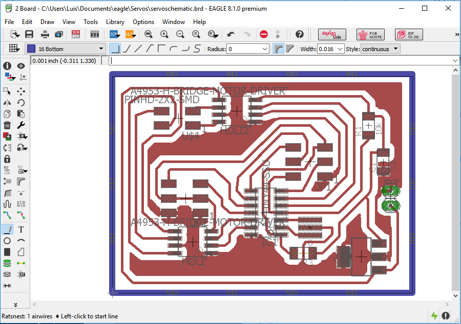
After that, on the botton layer, I draw a rectangle around the board for delimiting the path that was going to be cutten by the milling machine.
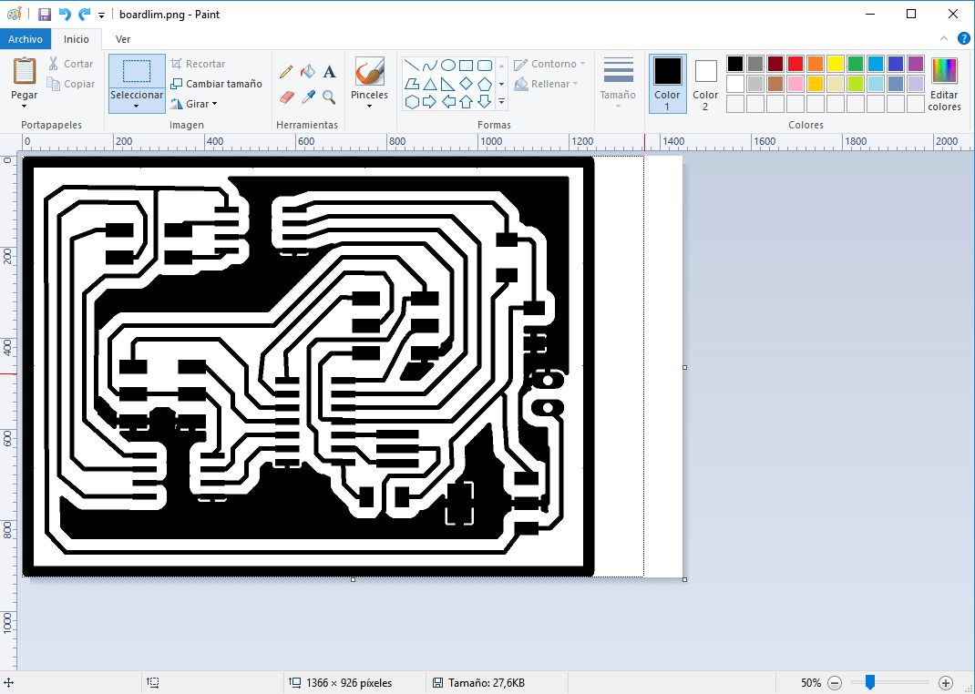
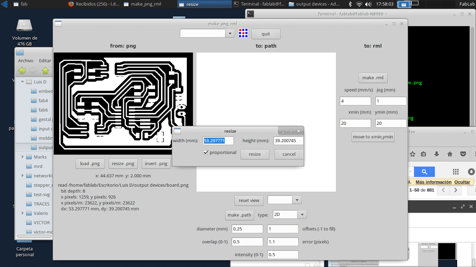
Then I selected only the top layer in layer settings and exported it as an image, but because of some reason, the exported image was bigger on the left side of the circuit. So i tried to edit the image on paint, moving it to the left side and shorttenning the dimensions of the image. However, this edition modified all the phisical dimension of the circuit when loaded on the fab modules.
So my solution, was to rotate the board on eagle 180 degrees so that the blank part were on the rigth side
Then I selected on layer setting the top layer, the pads and the bottom layer as visible.
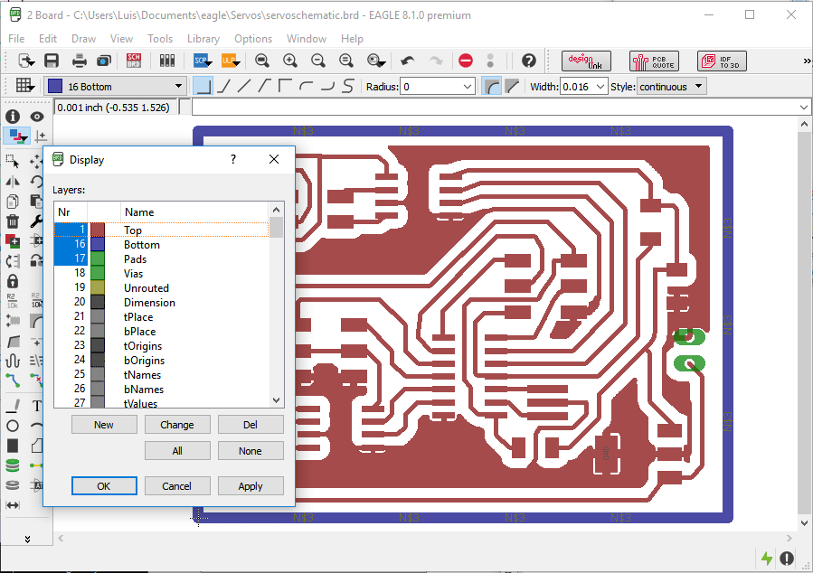
And exported the image with a 600 dpi resolution and the monochrome option active and named it as "boardlim".
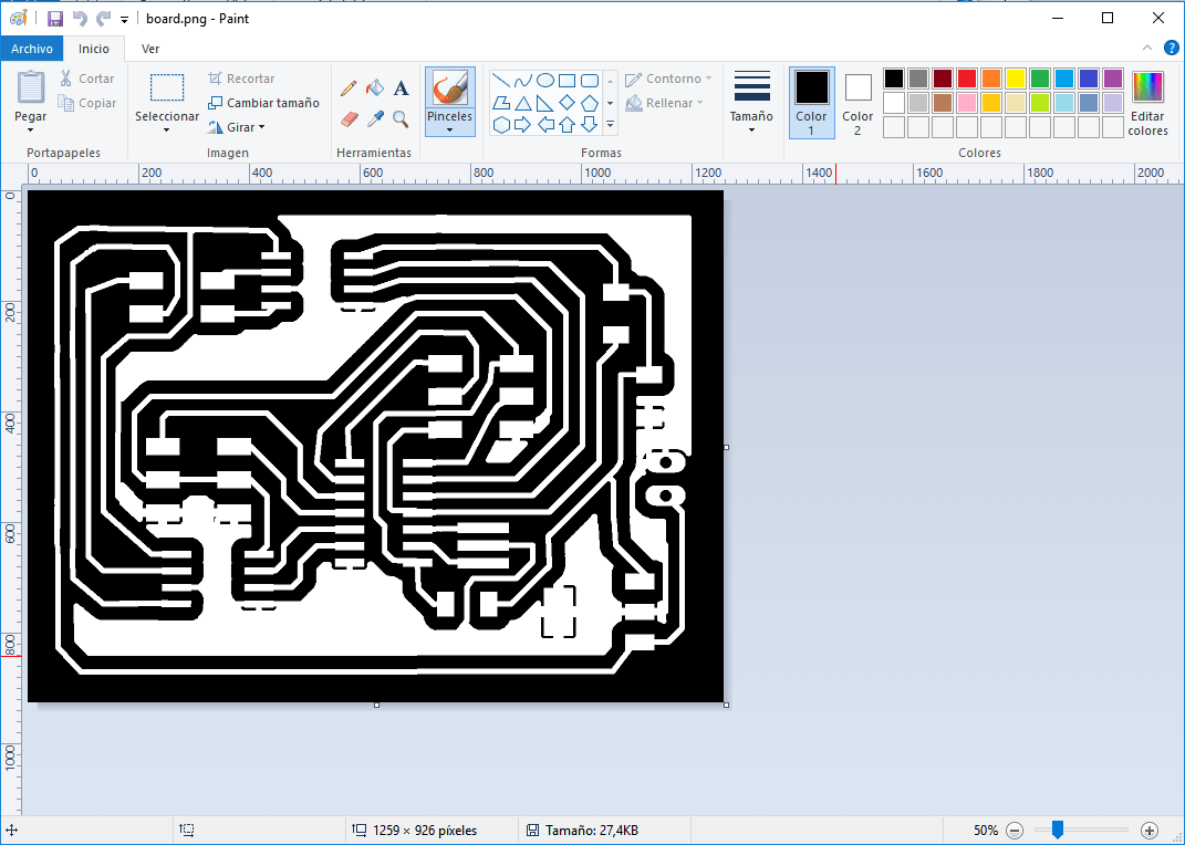
Then, I oppened the image on paint and shortted only the right dimensions of the image, but did not move the image (this seemmed to be the problem).
After that, I created two copies of that file, and named each one as board and limits.
Then, I oppened the board file on paint, erased the external rectangle, inverted the color and saved it as "board" .
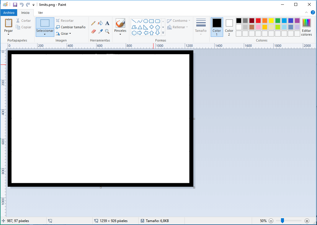
Then, I oppened the limits file on paint, erased all except the external rectangle and saved the file as "limits".
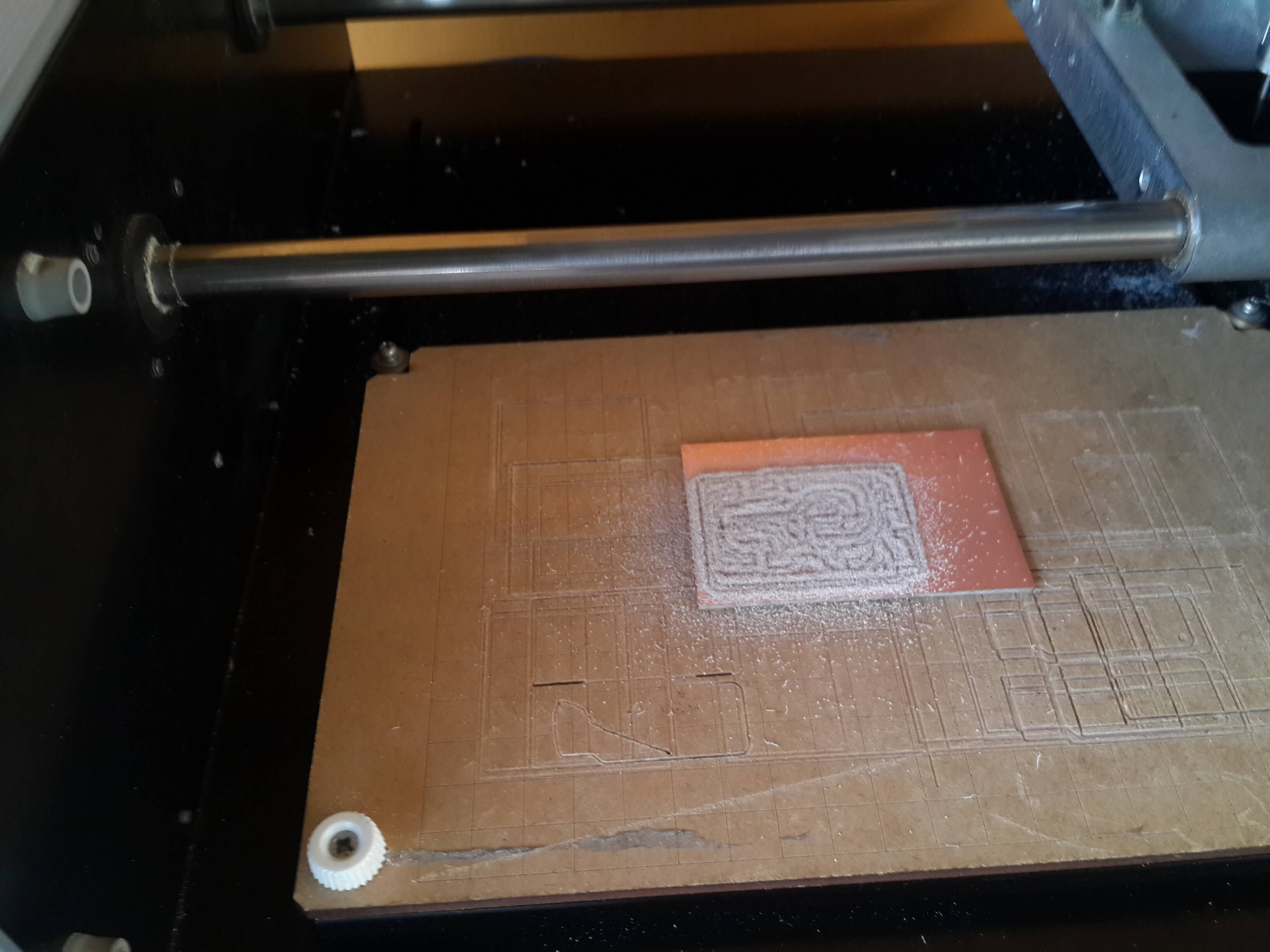
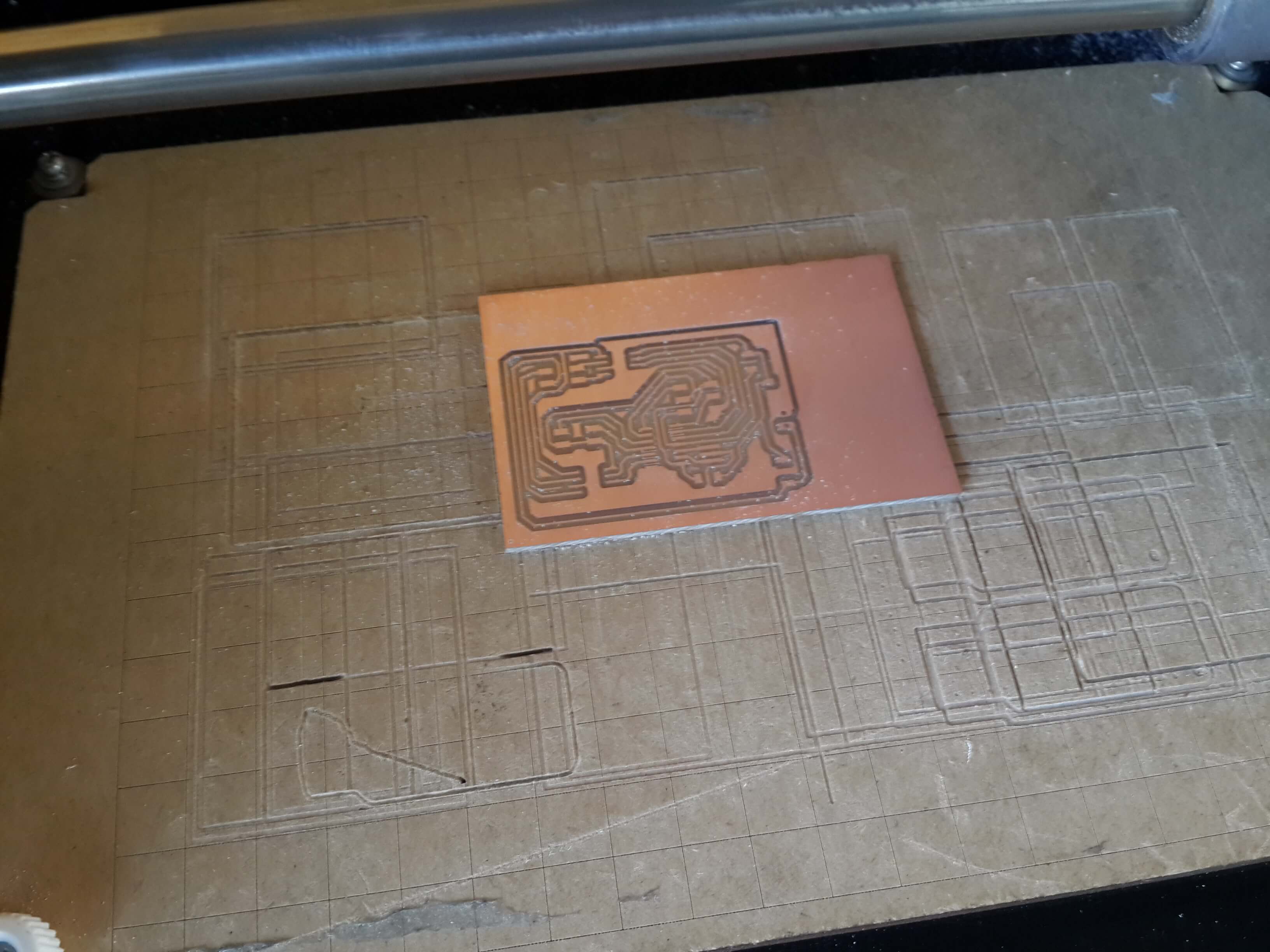
Making the Circuit
I oppened the fab modules and loaded the boardlim image, which is the image that was not editted, clicked on resize, coppied the width of the image and clicked on cancel.
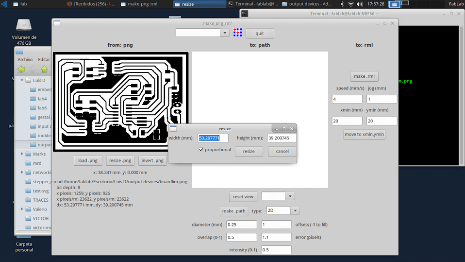
Then I loaded the board image, clicked on resize and pasted the on the width field the width of the boarlim image. And then I did the same on the limits image.
The rest of the procedure it is the same explained here for working with the milling machine MDX-20.
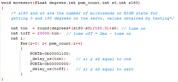
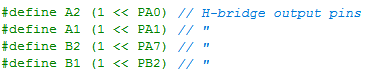
Programming the Microcontroller
This are the steps I did for programming the control logics of both motors and uploading it to the microontroller:
a) Programming the motor controllers
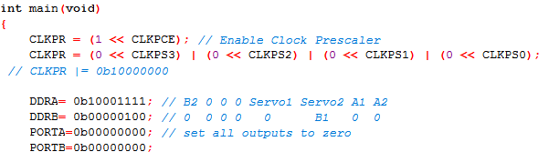
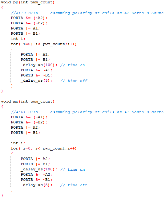
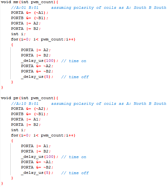
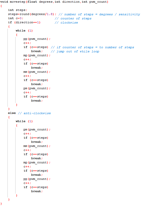
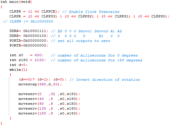
This are the steps I did for uploading the program to the microcontroler:
1. I downloaded the Makefile provided on the Academy page for using it to burn the fuses of the Attiny so that it setted the clock speed as 20 MHz.
2. I opened the windows commad line interface on the location of the makefile. This is done by holding shift and right clicking on the window.
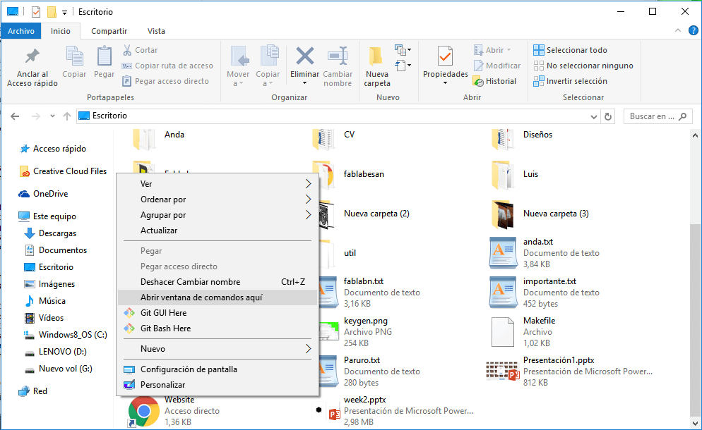
3. Then I oppened the Make file and made sure the variable F_CPU was set to 20 Mhz, and closed it.
4. On the command line I wrote the next comand for burning the fuses:
make program-usbtiny-fuse
5. I opened the Mfile software that came with the Winavr installation and setted the options as follows:- MCU Type = Attiny44
- Port = usb
- Programmer = ustiny (using Enable Edit)
6. Then, I saved the Make file in the same folder where the code was located.
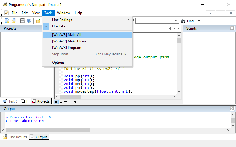
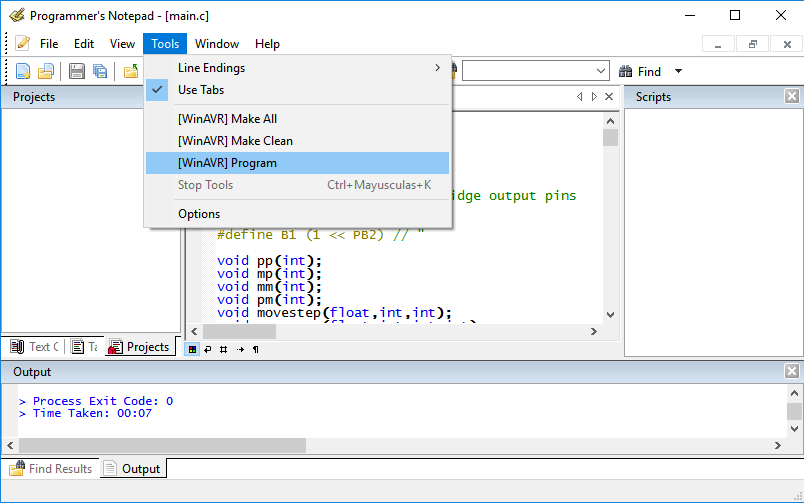
7. I connected the motors to the board and the board to the pc. 8. After that, on the programmers notepad software, I clicked on make all, for compiling the code; and then, on program, for uploading the program to the microcontroller.
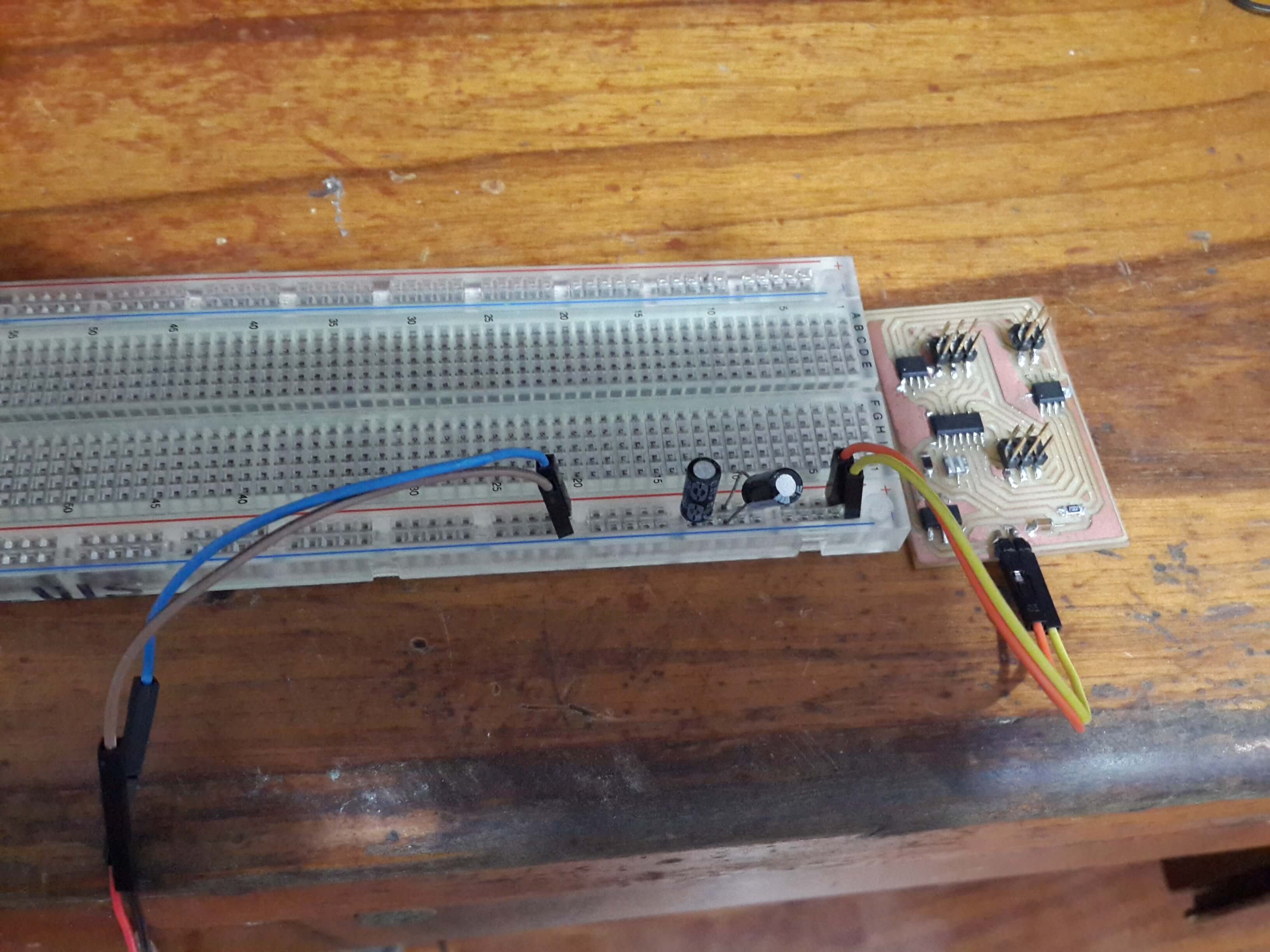
So, after connecting the protoboard to the board and programming the board, this is what I got: