Project Development
For this assigment, we have to:
- (DONE) Complete the final project. Track and document the progress.
All the files created for this assigment can be found on the link bellow:
---> DOWNLOAD FILES<---
Have you answered this questions:
- what is the deadline? How much time do I have left?
--> yes
- what tasks have been completed, and what tasks remain?
--> yes
- how will I complete the remaining tasks in time?
--> yes
- what has worked?
--> yes
- what has not?
--> yes
- what questions still need to be resolved?
--> yes
- what have you learned?
--> yes
Questions to answer
a) What is the deadline? How much time do I have left?
The deadline is on monday 19 th. I've started to wort in my final project almost three weeks and a half before the deadline.
b) What tasks have been completed, and what tasks remain?
All the tasks have been completed, but what remains is to add an application to the project
c) How will I complete the remaining tasks in time?
I will program what remains as soon as I can
d) What has worked?
The communication between both boards have worked. The control of the motors has worked too.
e) what has not?
Unfotunatelly there is too much noise on the wireless communication, and as a consequence I can not control all the motors individually
f) what questions still need to be resolved?
How can I make this portable, knowing that it requires more than 3 Amperes to work?
g) what have you learned?
I have learned to manage my time and do complex projects in a short time.
Developing the project
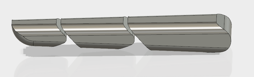
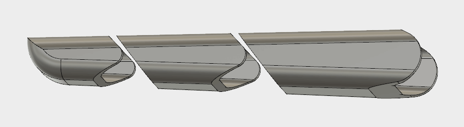
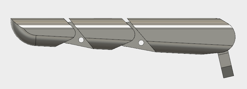
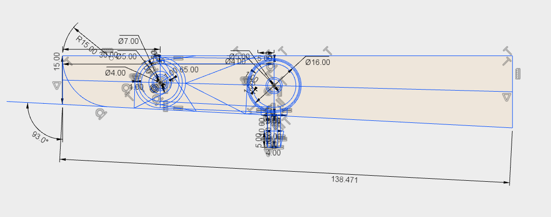
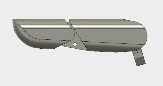
a) Designing the hand, wrist and fingers:
The first thing I did was to design the hand and the fingers
This are the steps I did for designing the hand:
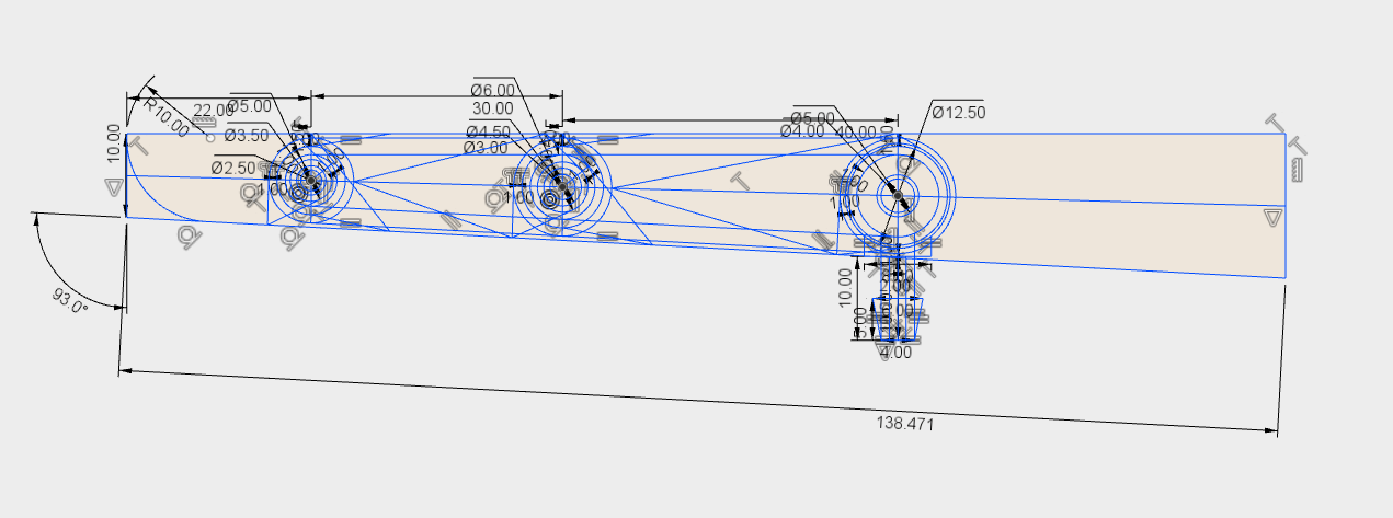
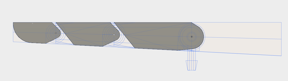
1. I sketched up first the side view of a finger with its phalanx and its joints.
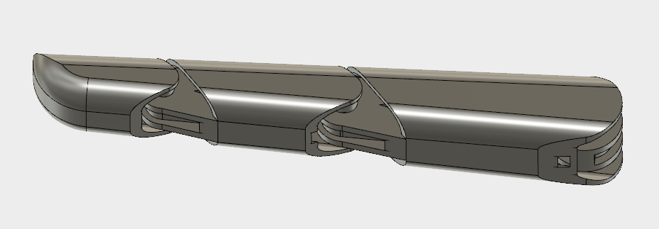
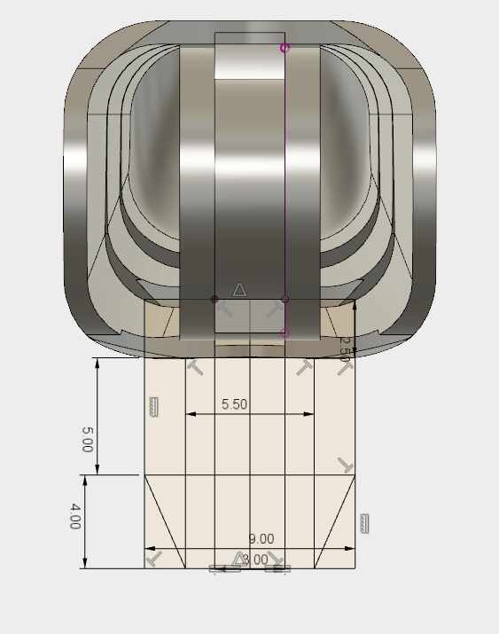
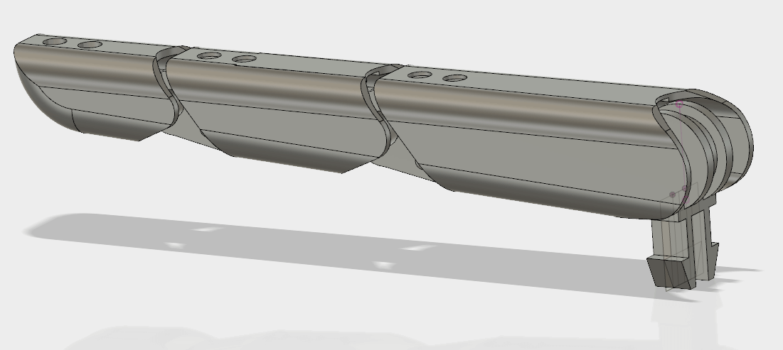
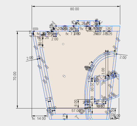
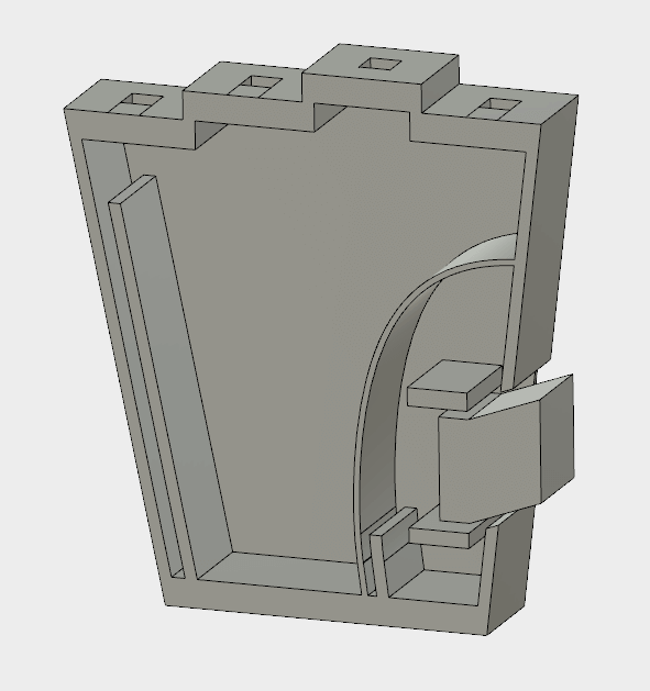
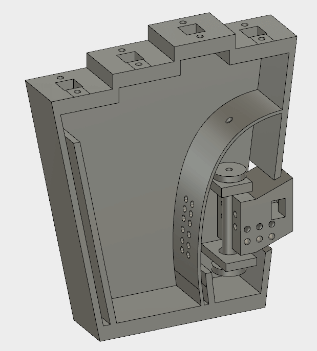
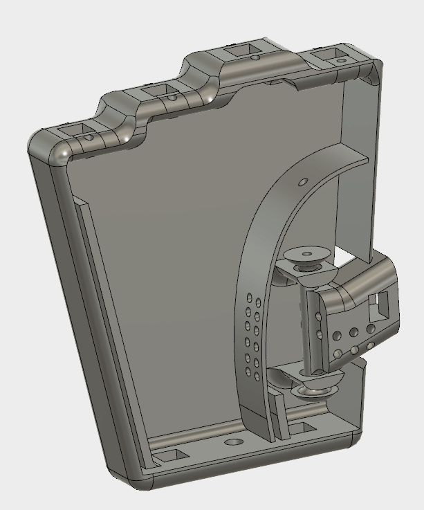
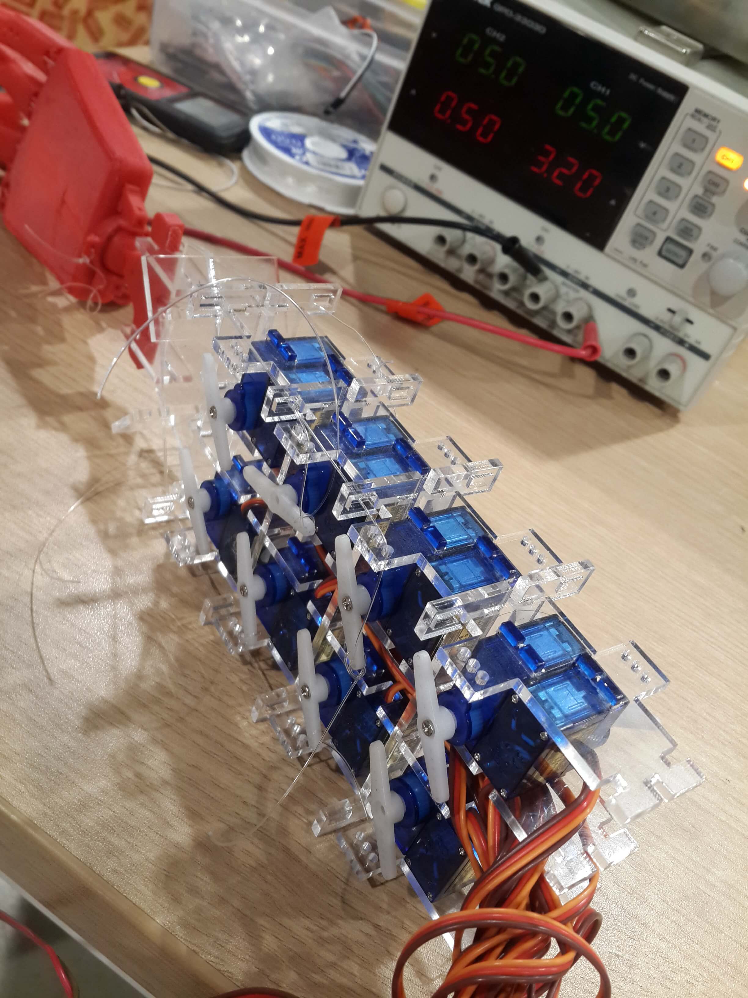
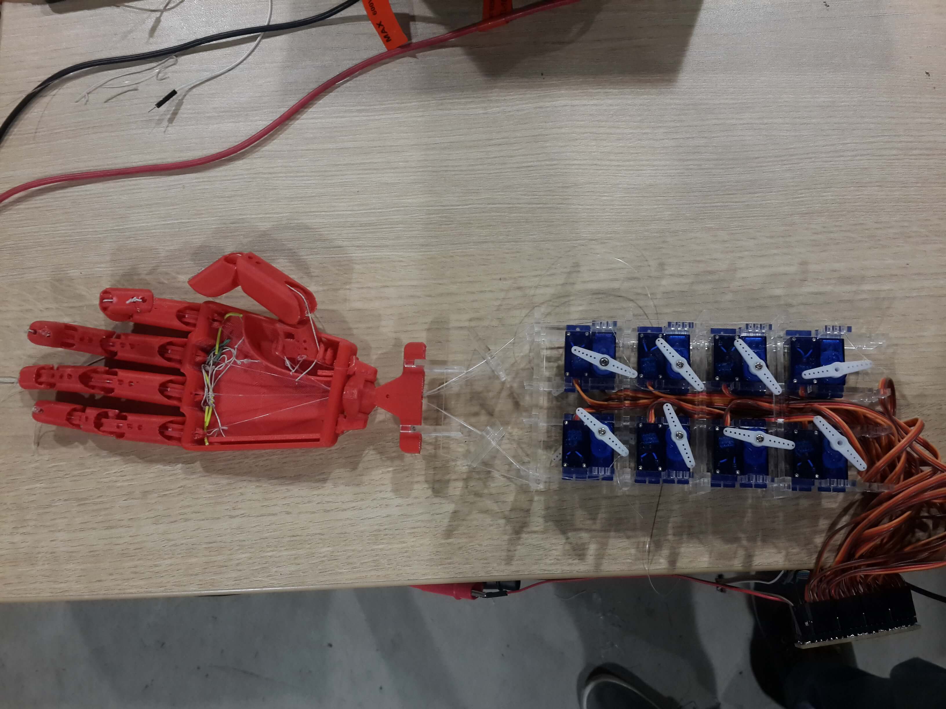
b) Designing the servo motors container:
I needed to put 16 servo motors in a very short space so I designed a double sided servo motor container
This are the steps I did for designing the servo container:
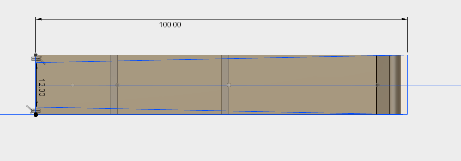
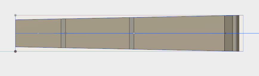
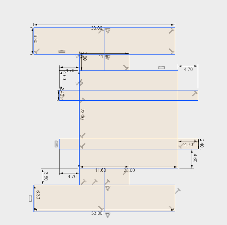
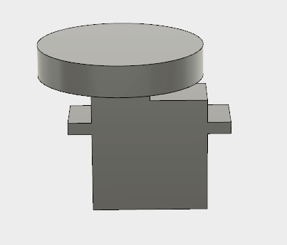
1. I started by designing a servo motor in fusion, so I took some measures from a servo, sketched it up and then did some extrudes.
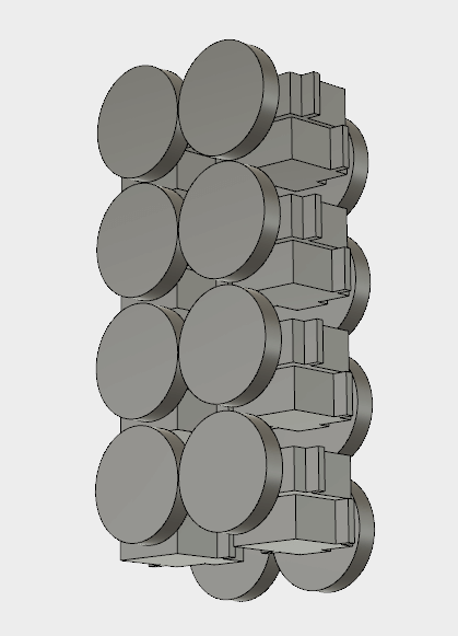
4. I started to sketch the container parts, considering the cables, the heith and the vias for the fishing lines
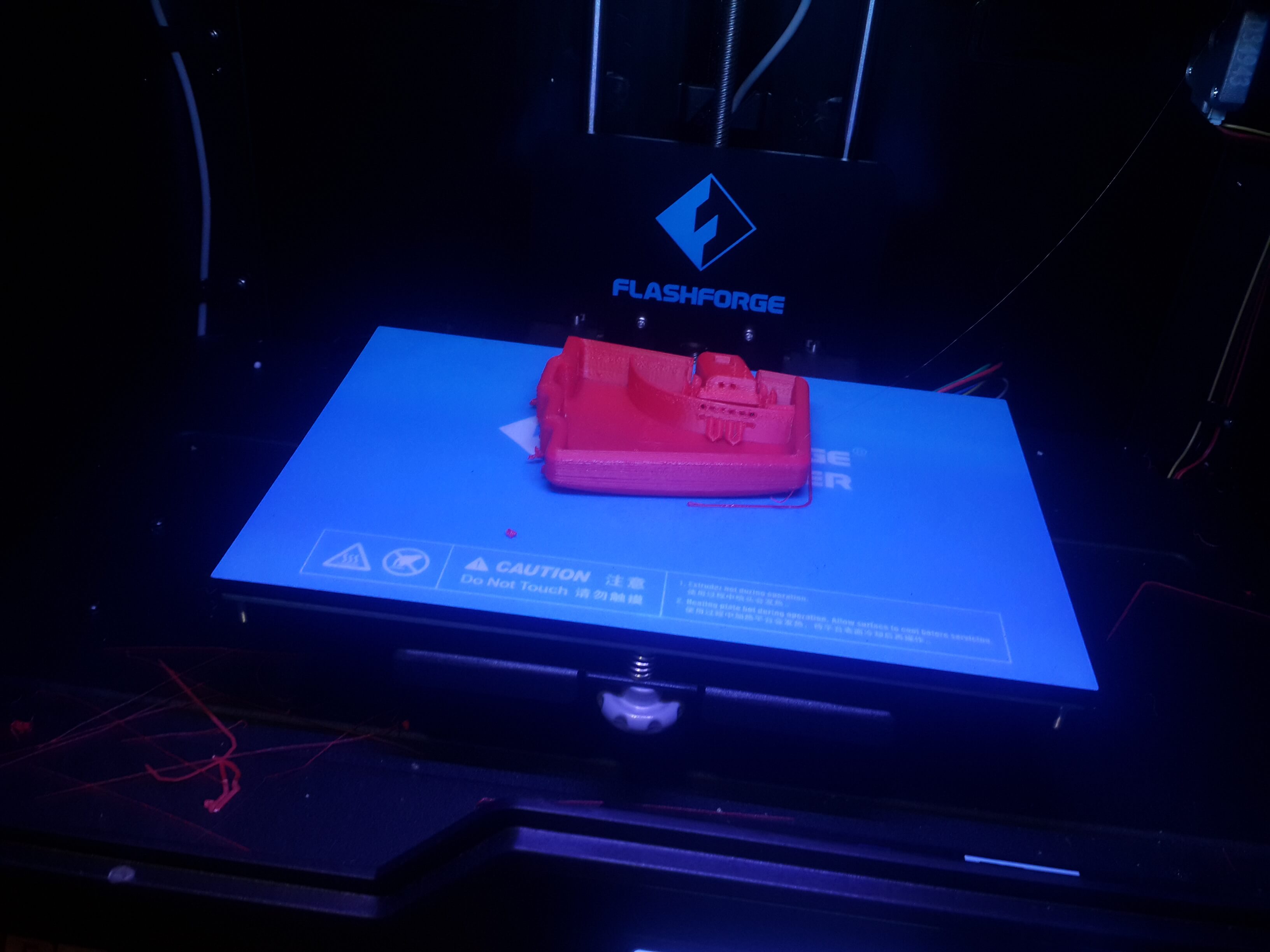
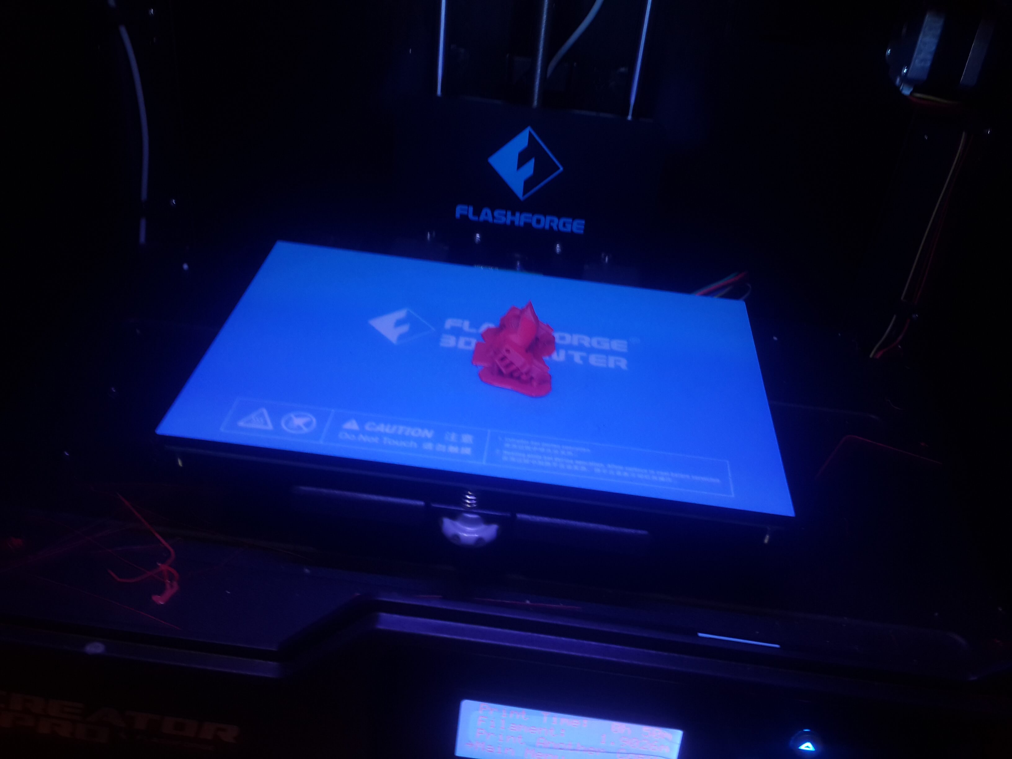
7.Then, I cutted all the parts of the container, and joined them all with the servo motors
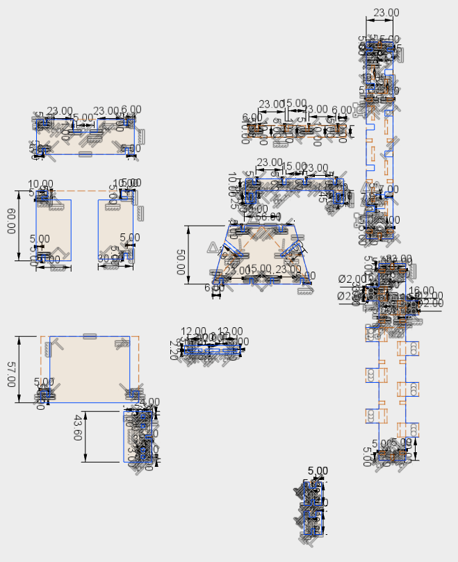
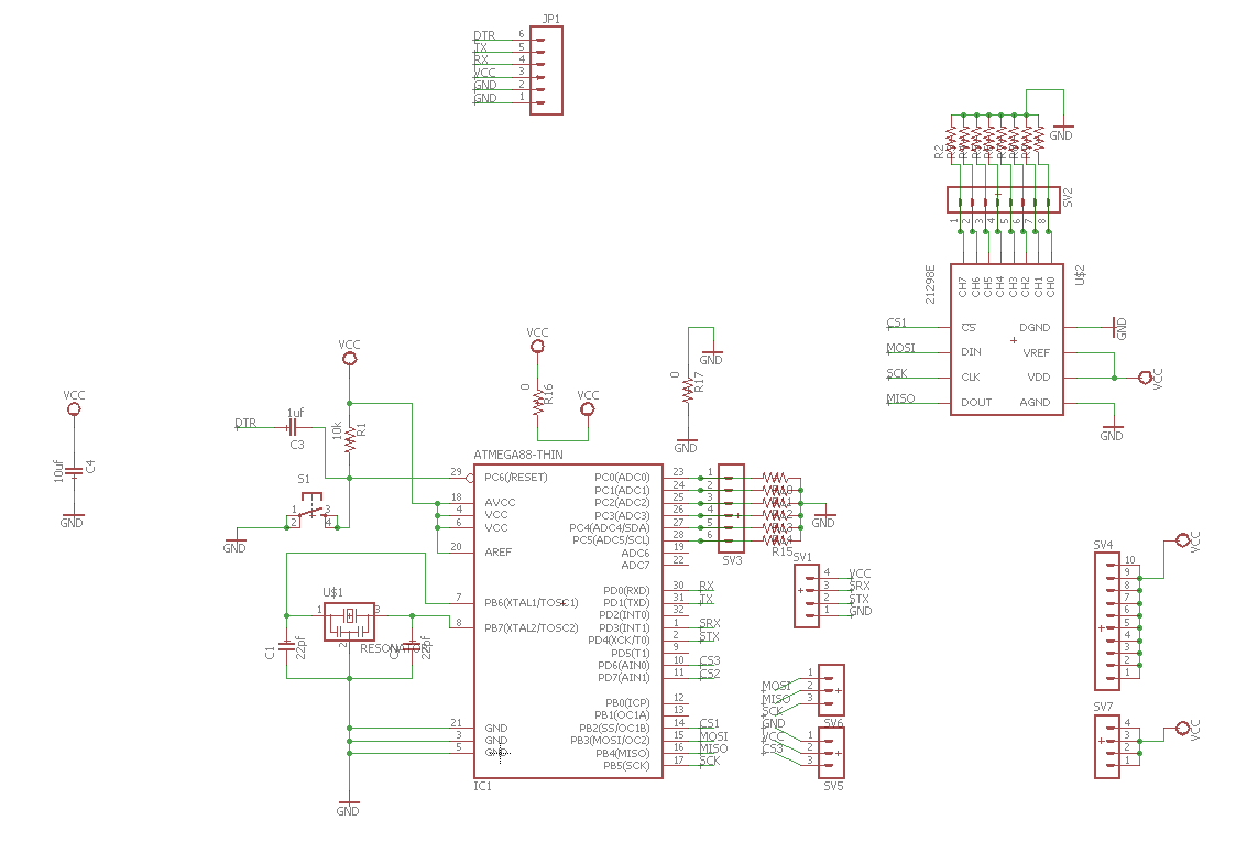
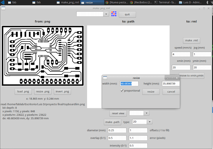
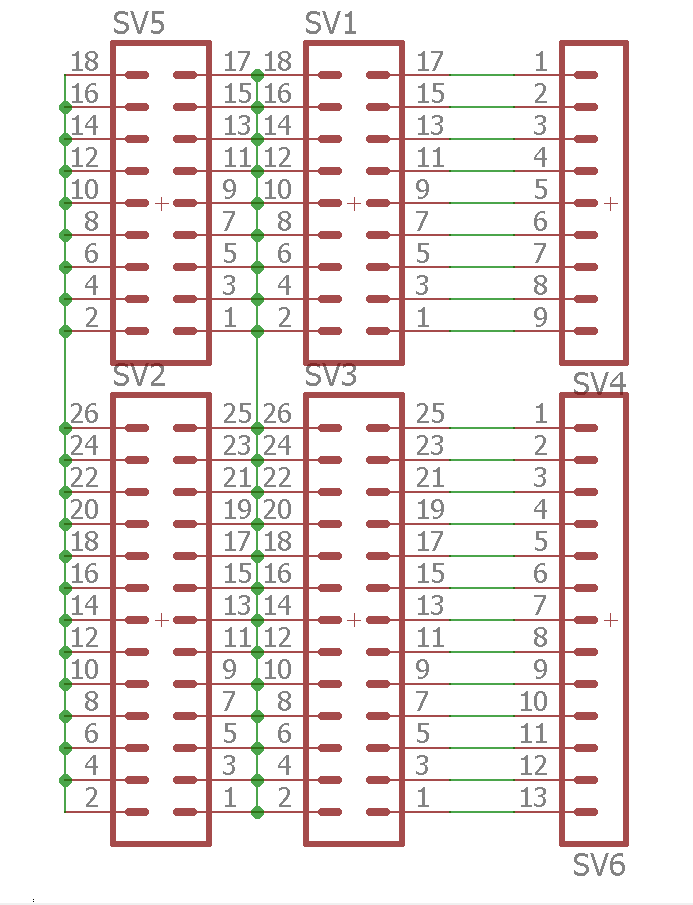
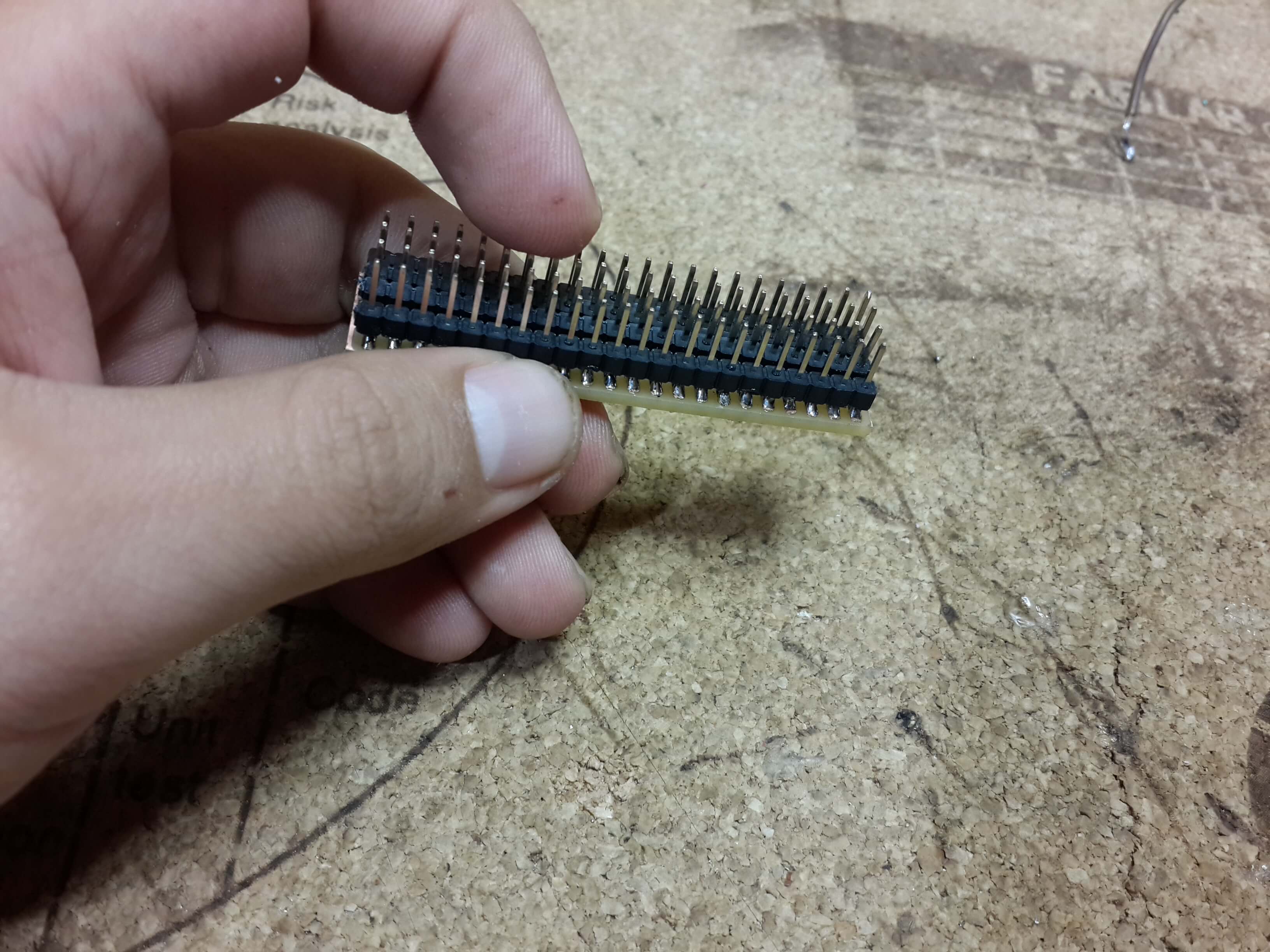
d) Designing the boards:
I needed to made three boards: two for the input device and one for distributin energy and signals to the servo motors.
This are the steps I did for designing the input device boards:
1. I made the schematic on Eagle, basically the boards consisted on an atmega328, a bunch of resistors, and an analog to digital converter.
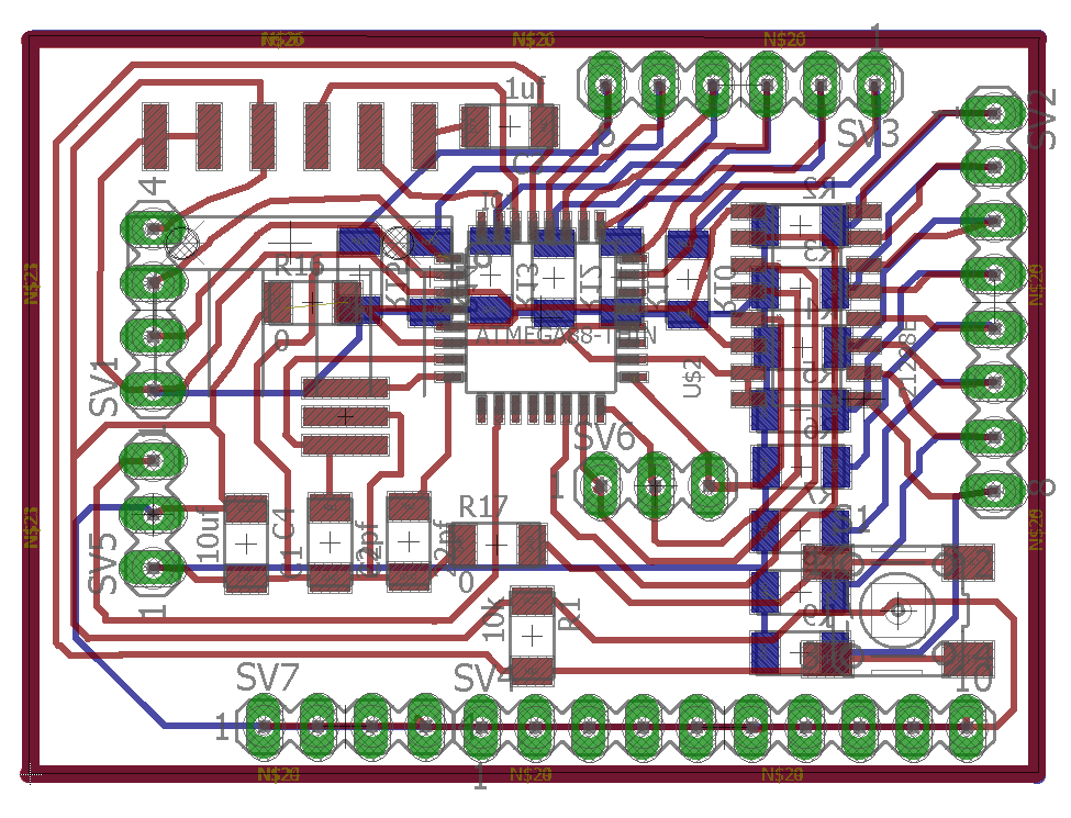
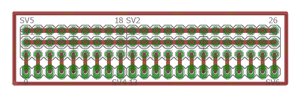
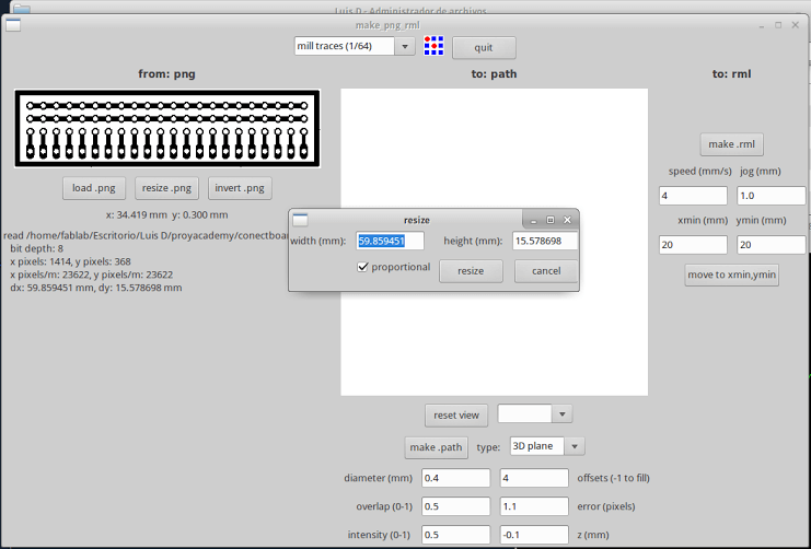
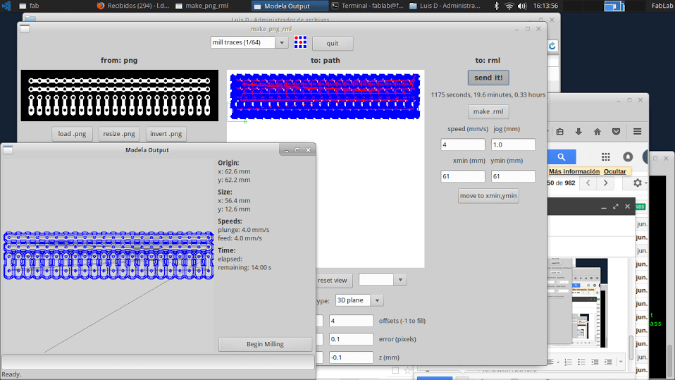
4. then I exported the bottom side of the board with its limits, maked it a mirror and then did the same procedure for separating the limits and the board.
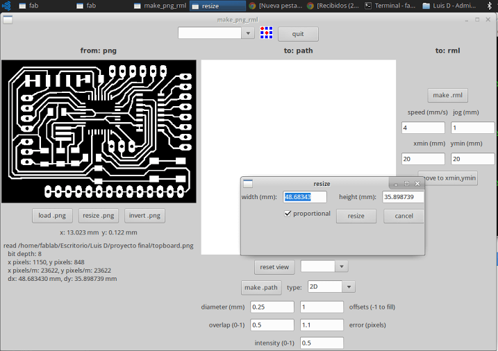
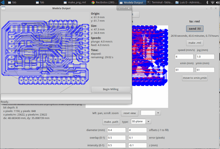
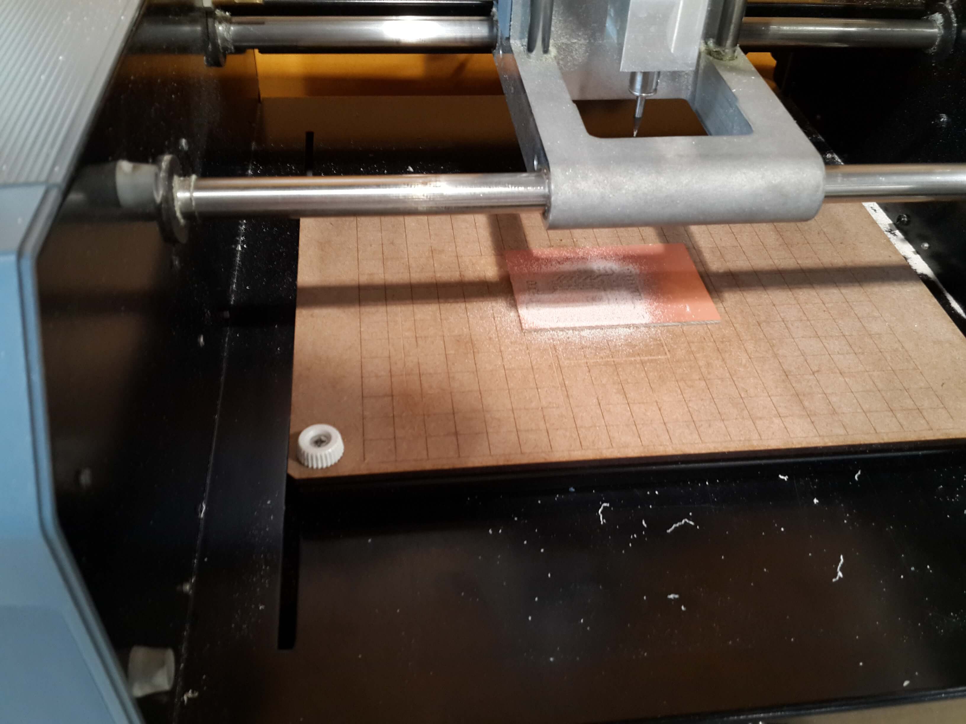
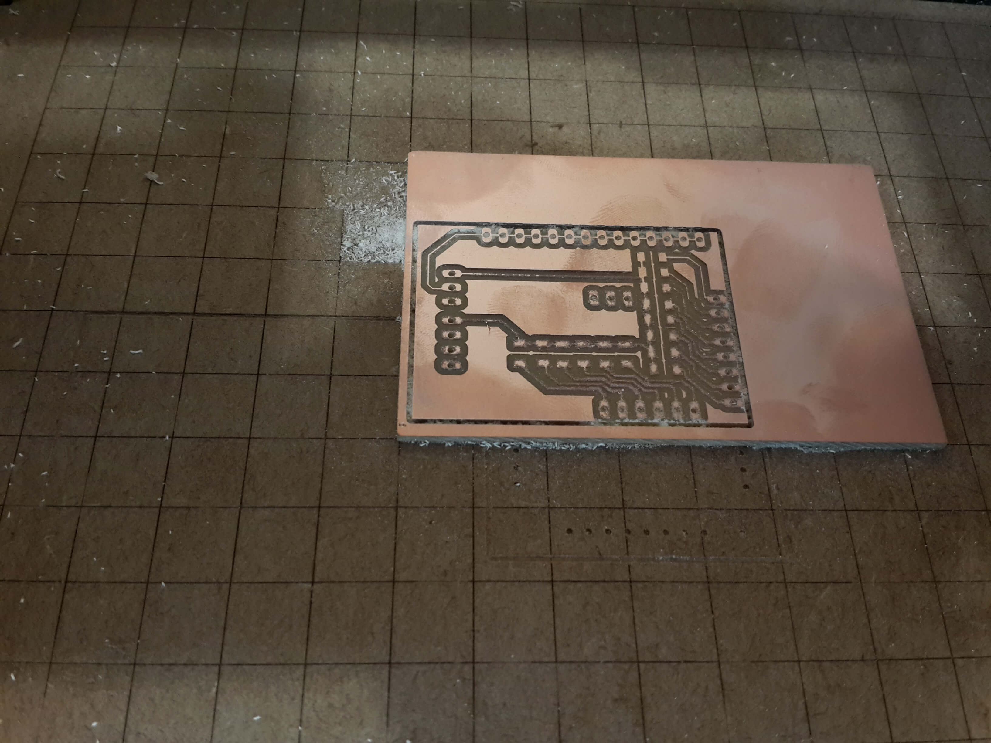
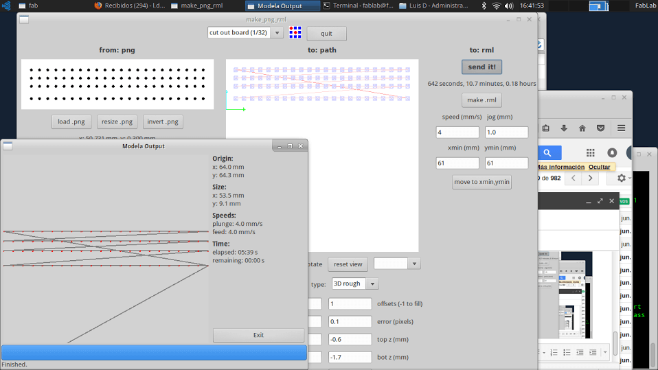
5. I loaded the top board on the fab modules, resize it based on the original exported file and sent it to mill.
On the other hand, this are the steps I did for designing the supply voltage board:
1. I made the schematic on Eagle.
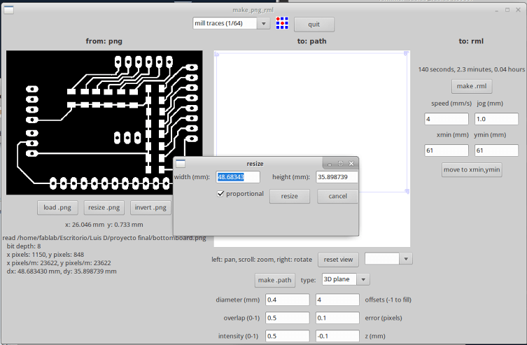
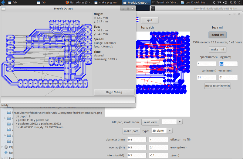
4. I loaded the board on the fab modules, resize it based on the original exported file and sent it to mill.
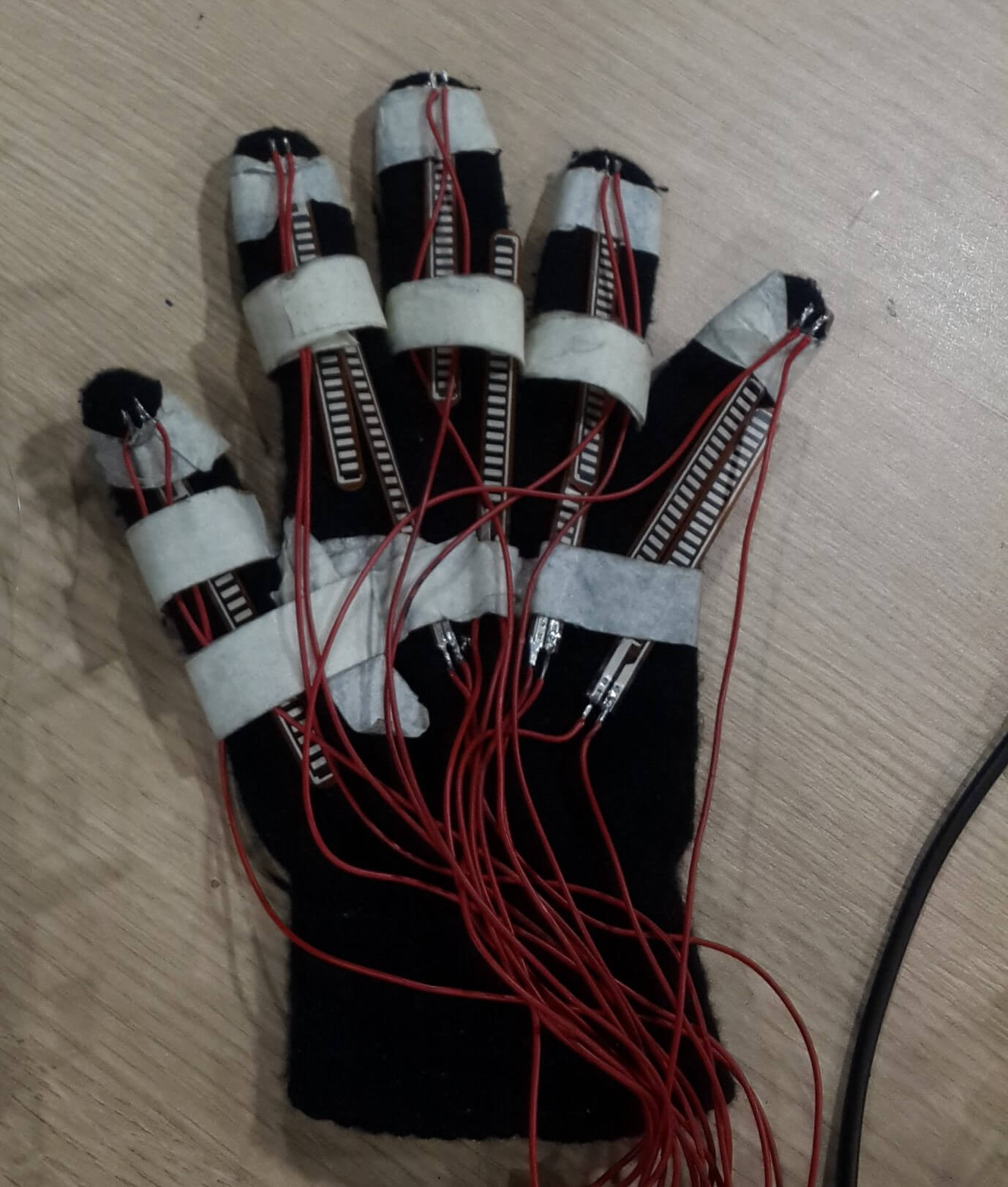
e) Mounting the flex sensors :
I needed to mount 9 flex sensors over a glove, which was not easy. Since the size of the upper side of the hand increases when the fingers are compressed, flex sensors can not be attached by both sides, they have to be attached only by one side, so that when a finger bend the sensor does not break.
So, the solution for having more than one flex sensor on a finger, is to put one flex sensor attached to the nail and one flex sensor attached to dorse of the hand, they will both overlap, but they wont break.
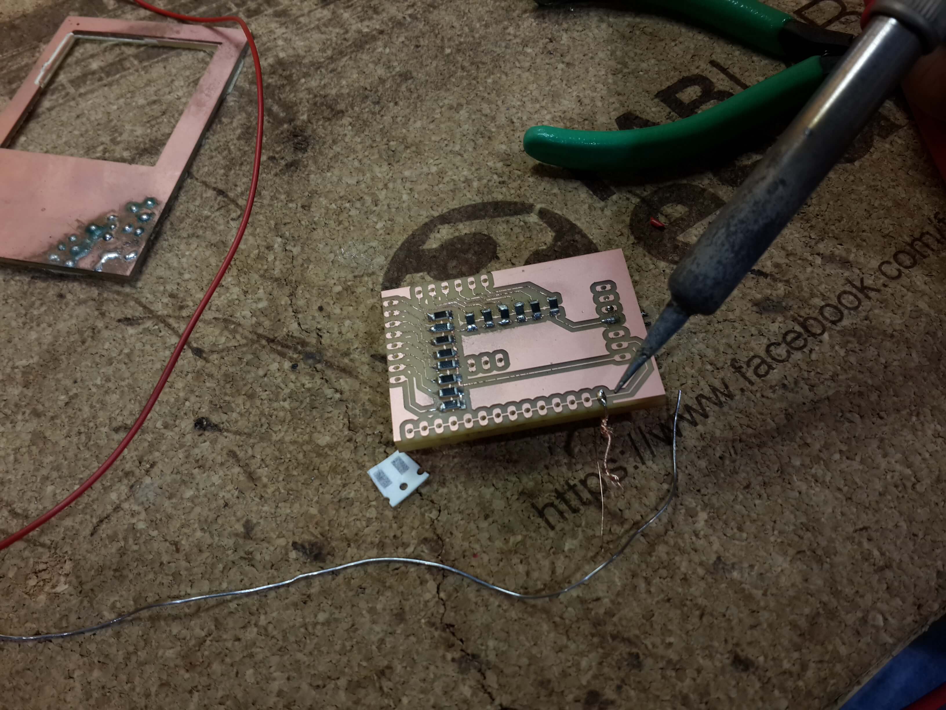
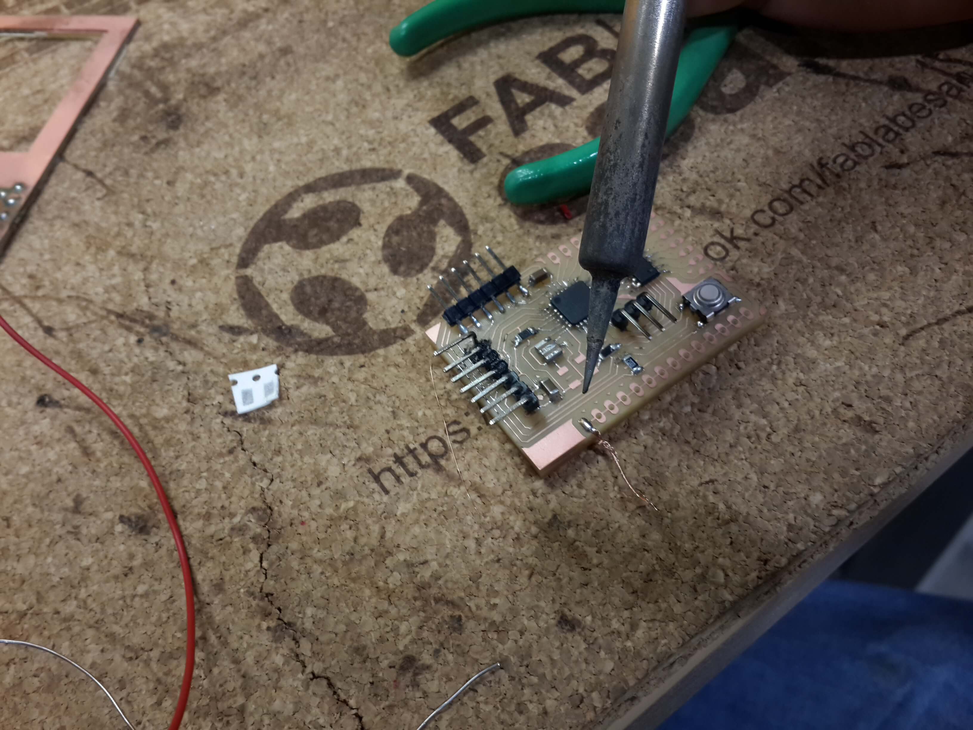
For attatching the sensors I used scotch tape. And once I positioned them all in the glove, I soldered them with some cables to the input board
This is how it looks:
f) Programming:
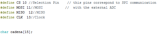
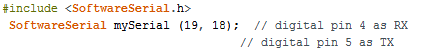
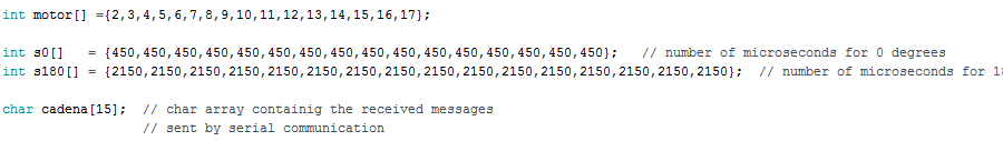
the input and output board need to comunicate to each other wirelessly, luckly I have done this before on my 15th assigment by bluetooth, so the code for configuring the modules is the same that the one used on my 15th assigment. The input board needs to send just a value to the output board and that value has to be interpreted on the output board
The code on the input board works as follows:
1. First, it initializes the software seraial library and the virtual UARTt


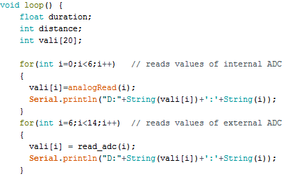
6. Then, it sends the resulting value to the bluetooth module
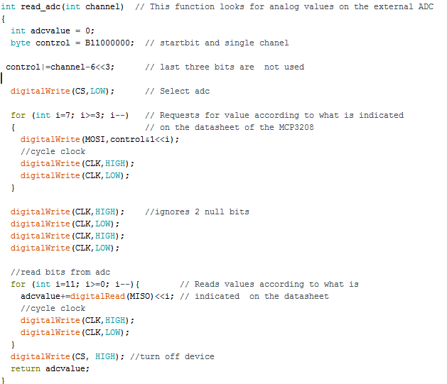
7. Finally, the function for reading values of the external ADC is defined.
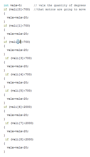
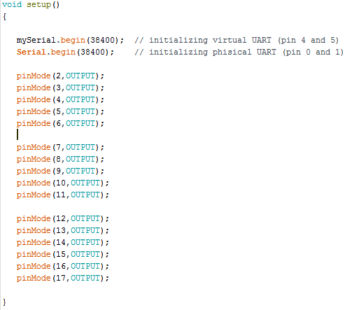
On the other hand, the code on the output board works as follows:
1. First, it initializes the software serial library and the virtual UARTt
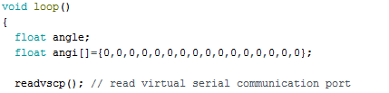
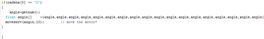
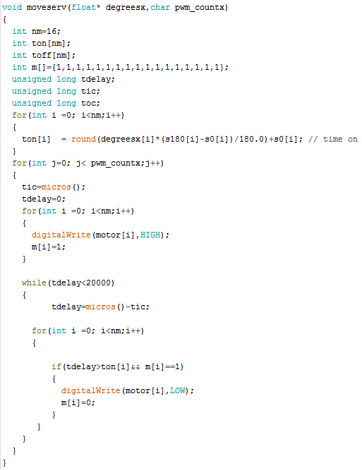
6. Then , it defines the moveserv function, which calculates the duty cycle of the pwm signal to be sent to the servos and controls all the servos at the same time.
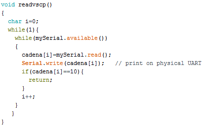
7. After that, the function readvscp is defined. This function reads the data comming to the virtual uart and allocates it in an array called "cadena".
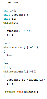
8. Finally the function getnum is defined. This function looks for the numerical values stored in the array cadena.
This is the code in action:
Brief Summary
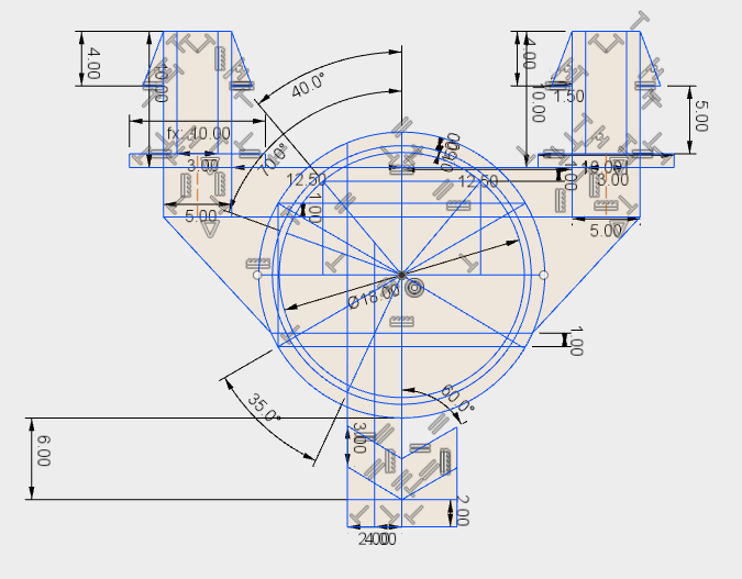
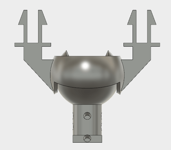
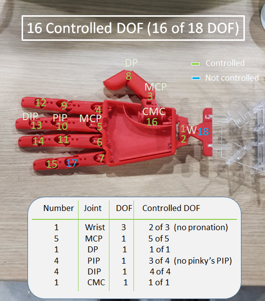
This Project consited on building a multi DOF arm, the image bellow shows all the joints on the arm, the ones that are controlled by fishing line are shown in green and the ones that were not controlled are shown in blue.
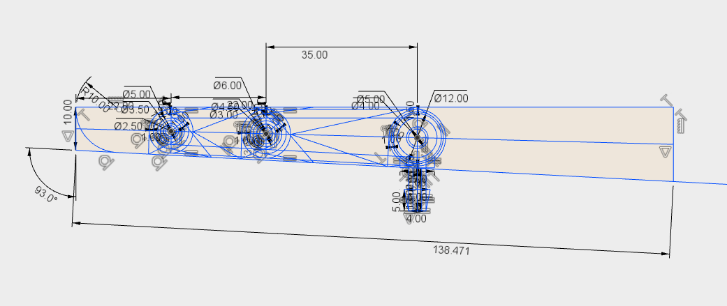
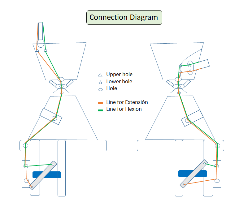
The connectiong between the threads and servos is almost the same for every joint, the image bellow shows the connection diagram for the control of a joint located on one of the fingers between the index and the pinky finger (at the left) and the connection for the control of a joint located at the thumb (right)
The connectiong between all the boards and devices is shown bellow

Bill Of Materials
Considering that this project uses a Fabduino that was made on my 8th assigmnt, the BOM would be as follows:Electronics:
- 3 PCBs of 2X3 inches
- 2 Atmega 328p
- 2 Ceramic Resonator of 20mHz
- 2 Tactile buttons
- 16 Micro Servo SG90
- 9 Flex Sensors
- 2 meters of Multi Strand Cable
- 2 Bluetooth HC-05
- 2 Ceramic Capacitors of 1 uF
- 1 Analog to Digital Converter MCP3208
- 2 Resistors of 10K
- 14 Resistors of 100K
- 3 Resistor of 0 Ohm
- Male Pin Headers
- Female-Female Duppont Cables
- Soldering Paste
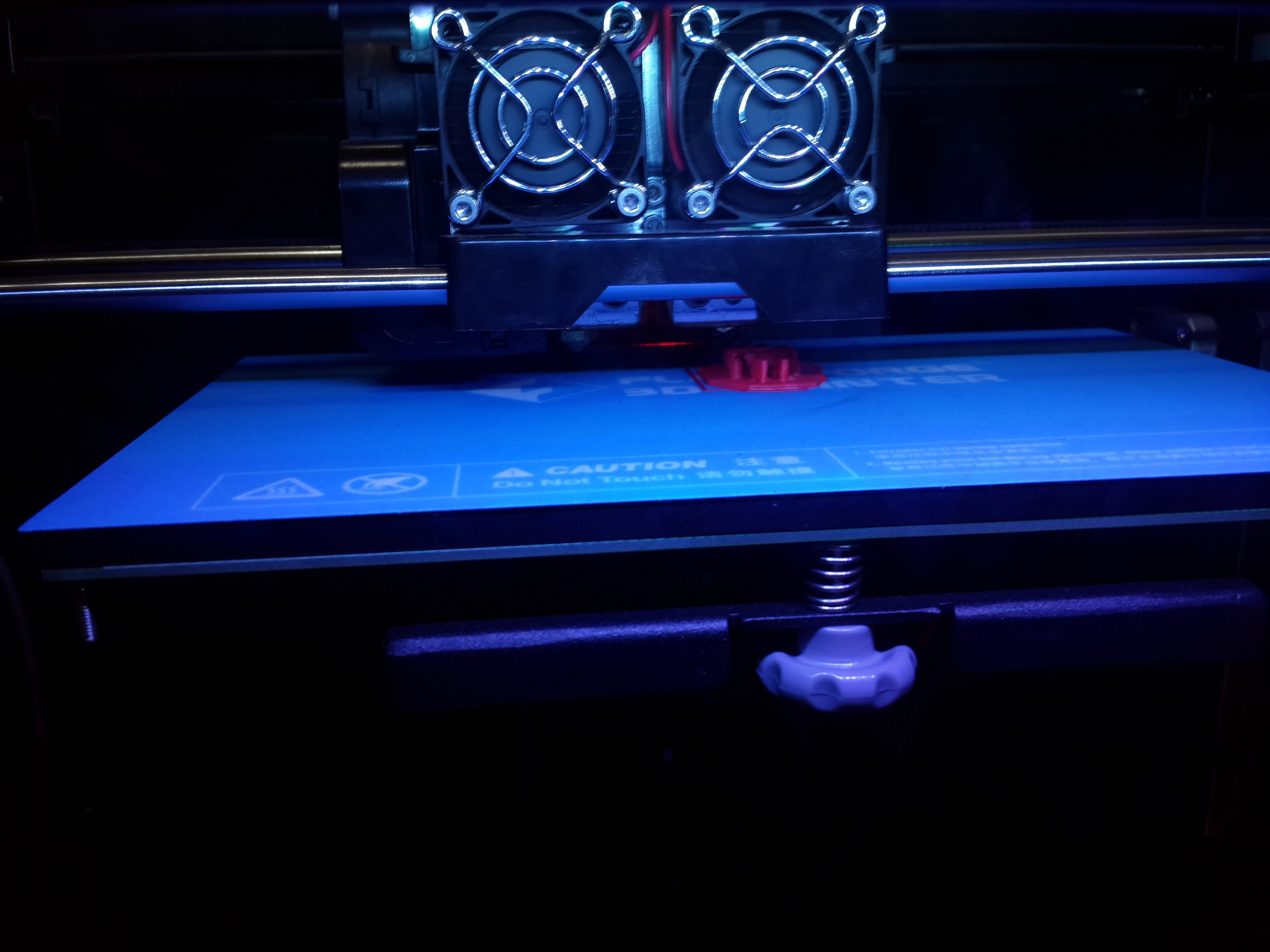
3D Printing:
- Printing Filament
Lasser Cutting:
- 1 Acrylic board of 300x600 mm
Tools:
- 1 FTDI Cable
- 1 AVR-ISP Programmer
Equipment:
- A Milling Machine
- A soldering station
- A 3D printer
- A laser cutter
- A computer
Others:
- Scotch tape
- A glove
- Fishing Line of 2.5 mm
Future Works
Since, this project was oriented to develope a robotic arm instead of a dataglove, most of the work was centered on the arm. So, in future works I will improove the glove by replacing it with a 3D printed exosqueletal hand, which probably do not use the same sensors. However, an inmediate solution for improving the glove would be to replace the cables with conductive thread, to attatch with thread the input circuit board to the glove and finally to replace the scotch tape rings with 3D printed rings.
This project is licensed under a CC-By-NC-ND (Attribution-Non Commercial-Non derivate) Creative Commons license
